行政院國家科學委員會專題研究計畫 成果報告
三維幾何示意圖系統之運算性及可能性之研究-以
Eisenman 為例
計畫類別: 個別型計畫 計畫編號: NSC92-2211-E-009-060- 執行期間: 92 年 08 月 01 日至 93 年 07 月 31 日 執行單位: 國立交通大學建築研究所 計畫主持人: 張登文 計畫參與人員: 陳冠燁, 賴怡成, 張粧亭 報告類型: 精簡報告 處理方式: 本計畫可公開查詢中 華 民 國 93 年 8 月 17 日
3D Geometry Writer: Diagram Reasoning in Design Space Exploration
Keywords: 3D Diagram, Design Space Exploration, Geometric Reasoning, Peter Eisenman
Abstract
This paper is focused on establishing a prototype of design supported system to solve that how to set up a computable mechanism on diagram reasoning and thinking in 3D geometry. The framework of this system, 3D Geometry Writer, is constructed with three parts of manipulation mechanisms on design components in 3D geometry: operators, generators, and versions.
1 What is Diagram 1.1 Diagram as Writing
Diagrams, especially in architectural design domain, often represent the inductive logic and analyzed explanation of spatial transformation. Two famous examples are the analysis of Palladian villas done by Wittkower (1949) and spatial composition done by Rowe (1976). Diagrams in these researches provide both significant visual representation and inspiration for understanding the design. Furthermore, by declaring diagrams are another creative “writing”, architects, namely Eisenman, Koolhaas and Gandelsonas, start to “manipulate” diagrams into representing a different form making process. Consequently, design process is somehow equivalent to the sequential diagrams. As the visual and operational characteristics of diagrams, a tool, a writer for diagrams writing, can be useful and essential device for exploring the concept of ideas.
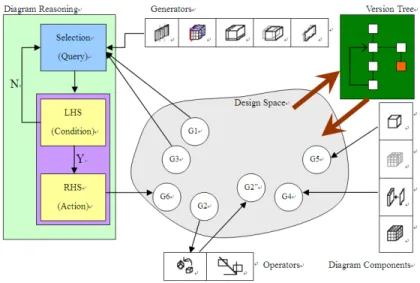
Basically, diagrams as shown in Figure 1 mainly represent the geometry transformation between different alternatives (also represented as geometries). Adapting this view, each diagram in this research is actually a solid with some embedded knowledge for the derivation between diagrams. The connection between different diagrams is the consequence of geometric operations from one diagram to another diagram.
Figure 1. Relation between Diagrams and Design. 1.2 What We Do
Follow the motivation described above, this research tries to promote the realization of form operation in early design stage. How to efficiently use the digital tool to aid generation and transformation about design diagrams in 3D geometry is our major task. However, it is lack an efficient tool for examine these diagrams in which the objectivity and conscientiousness are called in question. More, the usefulness of diagrams is just as icons if they lack a valid interactive interface.
We attempt to solve this problem through the examination of computational way. Therefore, the aim of this research is focused on establishing a prototype of design supported system to solve how to setup a computable mechanism on diagram reasoning and thinking in 3D geometry. The construction of system prototype should concern (1) human-computer interface such as the interface of direct manipulation in 3D geometry, rule reasoning interface and so on; (2) kernel of system such as the analysis of system level, definition of symbol level, and integration of 3D geometry model. For these reasons, the major scope of this paper is to provide the relative functions of kernel to describe the combined rules of 3D geometry. There are three items about our objectives:
(1) We will integrate 3D geometry model with logic computational system. (2) We want to find a simulation method on geometry types.
(3) Generation and Transformation of design diagrams in 3D geometry.
1.3 Existing Diagrams
To make the differentiation from bubble diagramming, we consider the transformation of diagrams in 3D Geometry published by architects at first. Through the representation of design diagrams at some spatial types, an implied structure and some compositional rules with certain degree of domain knowledge can be analyzed and recognized. These diagrams of 3D geometry are used to remove the complex mass of designing, and could be used as a descriptive tool of transform principles in spatial types.
The task of data collection is followed some principles to evaluate the completeness of data: (1) diagrams analyzed with a completely reasoning in geometry; (2) as possible as keep the personal description of design diagrams from designers such as texts or pictures; (3) it could be followed the transformation of space in 3D geometry; (4) diagrams must make by designers themselves. Therefore, we did not choose the first and third types of data. This is because the first type of data have some difference on analyzers’ biases, it usually also be selected with a specific purpose. And the third type of data would be selected without a direct relationship. In other words, we chose the second type as the standard of data collection in this paper.
However, diagrams in 3D geometry are also easy to be transformed into digital data. Design diagrams of P. Eisenman’s pieces (1999, 1987, 1982), shown as Figure 2, are good illustrations of spatial transformations for the possibilities of digitalization in design details. These works are represented the single building by diagram presentations. It is suitable to use as the research materials of 3D geometric diagrams.
Figure 2. Diagram Samples from P. Eisenman’s Pieces. 2 Diagramming with Reasons
2.1 Design Space Exploration
In the digitalization of spatial diagrams in 3D geometry, how to convey design principles of spatial transformation is another key issue on design researches. A framework called design space explorer can extensively be recommended a metaphor of design behavior: search, or exploration. Design space explorer is used to simulate the design as a selective behavior with intelligence in a possible infinite design space.
The composition of a design space can be separated into following factors in current researches of relative issues: (1) the description of design structure such as graphs and nodes; (2) initial design problem; (3) design transition; and (3) the satisfied solution with particular explanation and complete analysis. In this possible infinite design space, designers could explore all possibilities of design results, find a newly design, record or completely imitate a resolved result (Woodbury and Chang 1995a, 1995b; Woodbury 1996).
2.2 Exploring Design with Geometry
Based on the framework of design space exploration, there are some relative researches about 3D geometry and knowledge representations such as Hesismann (1994) and Chang and Woodbury (1999, 2000). The main research issues they are aiming are: (1) one model unified the 3D geometric modeler and logic reasoning mechanism; (2) the similarity and matching method at 3D geometry; to provide for the possibilities of theoretic basis and implementation at the different layers of system integrations.
Nevertheless, the framework of design space explorer is too large to imply into this paper. We only appointed the logic of computational system in 3D geometry, and then applied design diagrams into the combined principles of design rules in design space explorer. With this simplified representation, we then describe the research steps applied in this research.
3 Fabrication of 3D Geometry Writer 3.1 Writing Pattern in Eisenman’s Diagrams
Same as the problem of knowledge acquisition in knowledge system, the objectivities and exactnesses in diagrams would be affected on an analyzer’s realization subjectively. In recent years, user-oriented analysis method is more and more important on using as a tool of hybrid principles to generate space types by diagrams. One of these is design generative system.
First at all, how to find some useful design patterns and then find some useful design components from these patterns is an important task of system design. We have an idea that a diagram can be regarded as an abstract composition of geometric objects. For this purpose, 3D Max software is used to find these patterns through reconstructing the P. Eisenman’s design diagrams, the processes are shown as Figure 3. It must be an intermediary type as medium if we want to find a meaningful transformation in design processes. This intermediary type is what we said that design patterns have relative connection in between geometry transformation and symbolic matching. We could use this relative connection to find the reasoning basis among different diagrams.
Figure 3. Analysis of Design Patterns Using 3D Max Software. 3.2 Representation – Geometry
We try to find out the design pattern of Eisenman’s diagrams by design analysis and design representation. This pattern is useful to describe a framework of our system into an embedded language of design diagrams. This embedded language could then be transited some rules of diagram reasoning in 3D geometry to generate a new design result. This pattern will not necessarily represent the actual intention of Eisenman’s and the reflection in his diagrams. As the purpose of this research, we might not even need it. The reasons are: (1) the referable design patterns is only needed to be used to be basic requirements of system design; (2) we select merely partial constructors which could be translated Eisenman’s design diagrams for testing the design parameters of system; (3) as the diagrams are the writing of some design knowledge from Eisenman, the validation of design intention with design strategies create a huge overhead even with such considerable text provided by Eisenman.
A 3D geometry writer must generate many design alternatives with variableness and multiplicity. It would be limited the generative results and shift the focus of this research due to consideration of Eisenman’s design strategies. Therefore, the simulated pattern is used as a reflection of Eisenman’s work and the patterns are based on the geometric consideration from any two geometries.
3.3 Reasoning with Rules
For establishing the diagram writer described above, all design elements are separated from original design objects with their diagrammatic characteristics. It is based on that how to use diagrams to aid design in design processes. Our starting point of this idea is focused on form in 3D geometry. The process can be distinguished into four elements: (1) components (2) operation; (3) rules; and (4) process. Therefore, a user how to interactive use the diagram as using the form is a key issue on designing 3D geometry writer system. To approach this issue, we believe that a feasible design result could be generated by diagrams while a designer uses them. Just like a text editor, 3D geometry writer system can record and retrieve a designer’s design processes using a design illustration. This
design illustration is implied that how a designer describes his ideas and searches the corresponding information for these in design results. In other words, it also implies that it is suitable to use design principles to a design rule-based system. We can setup some rules to process design reasoning from design patterns that we found.
We adopt two kind of action in design reasoning at this moment. One is to match some objects in 3D geometry in diagrams with constraints. Another one is to select a computational result with geometry transformation. Through the definition of symbolic meaning and manipulation of geometry transformation, we could use some feasible rules as the estimation of design reasoning.
3.4 Characteristics of 3D Geometry Writer
Based on the above views, we have an idea that the representation of design principle could be regarded as the intertexture with vocabulary and syntax in design language. It forms a design language to describe a designing form. Therefore, a 3D geometry writer system has three characteristics in design language:
1. Design components of system are equivalent to design vocabulary.
2. Operation and conjunction of system are equivalent to design syntax. All of both also can be specific ways of design representation.
3. An action of selection could be a presentation of design alterative. The selecting action on design components is equivalent to choose one kind of design manipulation. These characteristics of diagram writer would be extending a problem on design thinking: could different design processes merge into one design sequence if we merely select a component on different design sequence? Could this process be recorded? Have any possibilities of transforming design knowledge on different design sequence? To solve these questions, we think three directions of solutions that (1) each design diagram is equivalent to a sentence in design language; (2) establish a design process with history function; (3) integrated design processes are similar with a paragraph structure in design language. It could be formed as a text that would be used as a knowledge and change its composition on different relation of design sequence.
The combination of different design sequences are recorded design results as a version. We still have to consider how control a version manipulation: (1) we need a knowledge database to record the nodes and attributes for design results. It also contains the rules of design reasoning; (2) all version records will integrate into a tree structure; (3) each attribute can setup a value to preserve the current stat of design results; (4) a tag is used to make all nodes of design results.
In short, three constructors are used to design a 3D geometry writer system. These constructors are respectively built on design components. Figure 4 is shown as an interactive process of writing in entire system.
of design system. We call them operators. Operators must be fixed functions. They are used to change the attributes of design components in 3D geometry.
2. Generators: generators are different from operators. They generate some selectable design results by editing action and then match the varieties among different design results through the understanding of different case analysis. Editing action is used to produce new design components. It also is an elastic tool for rule reasoning. Basically, generators are constructed from many set rules and to generate the primary design component through the inspection of design conditions. Therefore, we have to think about each detail of rule before construct a generator.
3. Versions: we can arrange design components for a segment of design process. Versions can control each generation and transformation in design diagrams. They could keep the possibilities of design modification and incremental add a design result into working history.
Figure 4. Interactive Writing as a Process. 4 Implementation
4.1 System Framework
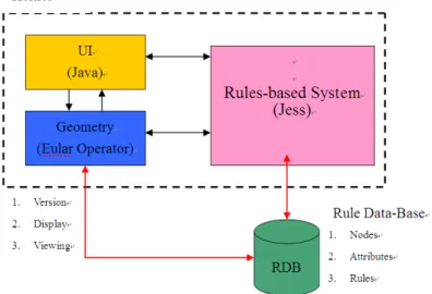
Based on analysis of Eisenman’s design diagram in 3D geometry, 3D geometry writer is constructed from following steps: (1) set up the representing mode of design knowledge on system design level; (2) establish the representing method of analysis diagrams in 3D geometry; (3) find a matching mechanism of 3D geometry from design reasoning analysis; (4) set up a format to record the formalized principle of 3D geometry. Figure 5 is shown as the system framework of 3D geometry writer.
vertex-based representation is an important factor in 3D geometry. We implement basic geometry modeling principles with Eular operators, and consider combining the design mechanism of version control. In geometry transformation, 3D geometry writer could be reached a multi-initiative state of version recording: (1) the user can revise one of version manually; (2) the user can change the recorded values of analyzed version; (3) it can generate a version automatically. Otherwise, we manipulate the following steps to design the geometry part of system: (1) user input analysis; (2) modeling simulation; (3) to establish data structure for modification and function; (4) to design a 3D display filter; (5) set up output geometric model.
We have to consider applying a version of historic record as well as rules in design components, even more the geometry representation. A diagram has many design results of geometry representation. One diagram will generate the next diagram through an operation and a limitation. We suggest two ways for implementation: (1) each diagram is regard as a state, each state exist one design result and one operation. This idea is similar with a sequential process of design; (2) from defined constraints and procedural actions, we can determine the possibilities of next diagram through different generators in design results.
Figure 5. System Framework for Realizing the Purpose of Diagram Writer. 4.2 Rules
In front descriptions, we have mentioned some design principles implying in design diagrams. Before translating these design principles into reasoning rules, we have to find out (1) elements of design components; (2) operation sequence; (3) possibilities of generalization. For this reason, we must decompose a diagram at first. We use the following ways to manipulate the decomposition task: (1) diagram analysis; (2) diagram reasoning; (3) domain insight for diagrams.
We generalize some constructive principles of reasoning rules from P. Eisneman’s Hosue cases: (1) House I: transformation making; (2) House II: shifting doubling; (3) House III: rotation doubling; (4) House IV: transformation inversion; (5) House VI: inversion & slippage; (6) House X: unit form extention.
JESS (Java Expert System Shell) is used as rules reasoning engine. We think that the symbolic matching could be easily used in diagram reasoning between one and another in 3D geometry. It could be presented geometry by symbol and could be transformed into the concrete meaning of design knowledge.
There are two practicable ways on version control: one is that system could generate a new version when any operation or action invoked. The benefit of this is focused on recording all of design processes of designers and simpler to program the system. But the major defect is that it would be generated a large number of version records. It also could be made troubles for selecting different versions if difference of each version is implicit. We adopt another way to reduce the above situation: first of all, set up a binary tree for version record. We set end-node of binary tree to the current state of version. The tag is used to record the additive component or used operation. It would be added a new node in binary tree when a generator is manipulated. Therefore, we could get an explicit result of diagram. We only traversal the non end-node in binary tree and add a new version on this node for recording the later action while the user tries to retrieve the previous version.
5 Examples
We implement the prototype of 3D geometry writer in six parts. The action of entire system is shown as Figure 6:
1. Geometry engine: for display the diagram in 3D geometry.
2. The geometric operations: for change the current parameters of 3D geometry. 3. Reasoning engine: we used Jess as our main engine for diagram reasoning.
4. The rules databases: containing the reasoning rules of Jess in 3D geometry knowledge.
5. Version mechanism: XML documentation as a record of version.
6. Interactive mechanism: user could interactively query the selection from reasoning engine and then enjoy the feedback of design results.
Figure 6. The Action of 3D Geometry Writer. 6 Conclusion
In usages of 3D geometry writer in design processes are shown as the following two aspects: (1) this system could be used as the presentation of problem solving or a kind of puzzle making in 3D geometry; (2) users could generate different design results in design processes.
On the other hand, 3D geometry writer could provide some important principles of geometry combination in form manipulation of feedback learning pattern. In other words, we can apply these principles directly to develop design concepts with diagrams in early design stage. It is also helpful to provide the positive benefit on design learning.
However, this paper is focused on using visualized representation of geometry combination in 3D geometry diagrams. It could be have some limitations on 3D geometry of digital model:
1. Level of abstraction: the normal computational mechanism is an infeasible way of rule matching in 3D geometry through the analysis of relative researches. We suggest that it could be solved by a kind of interactive method in expert system design.
2. Knowledge representation: knowledge representation is the basic framework of design space explorer. We suggest that it could be evaluated the feasibilities with integration of 3D geometry.
3. Geometry rules == diagrams: combination rules of 3D geometry would merge the condition and action into the definition of knowledge representation and levels of abstraction. We suggest that it could be transformed the suitable situation through the matching mechanism of 3D geometry.
4. Design space data format: the solution of record and retrieve the version tree is still not yet developed. We suggest that the XML documentation with knowledge database could be useful to solve this problem.
In sum, this paper is shown that how to decompose design diagrams using in early stage of design processes and then record the manipulating processes which imply with creative principles of geometry combination. But we must mention that the framework of 3D geometry writer is only provided a conceptual idea of 3D geometry to avoid bringing too much information of design results. Design inspiration and analysis processes will be emphasized through the usages of design diagrams.
References
Chang, T.-W. and Woodbury, R. F. (2000). Geometric Typed Feature Structures: Carrying Geometric Information using Typed Feature Structures. In Gudni Gudnason editor, Construction Information Technology 2000: taking the
construction industry into the 21st century. Volume 1, Pages 166-177. Iceland.
Icelandic Building Research Institute.
Chang, T.-W. (1999). Geometric Typed Feature Structures: Toward Design Space
Exploration. Ph.D. Dissertation. Adelaide University.
Eisenman, P. (1999) Diagram Diaries, Thames & Hudson. Eisenman, P. (1987) Hose of cards, Oxford University Press. Eisenman, P. (1982) House X, Rizzoli.
Heisserman, J. (1994) Generative geometric Design, IEEE Computer Graphics and
Applications, 14(2):37-45.
Rowe, C. (1976) The Mathematics of the Ideal Villa and other Essays, MIT.
Wittkower, Rudolf (1949) Architectural Principles in the Age of Humanism, St. Martin's Press