行政院國家科學委員會專題研究計畫 成果報告
子計劃三:寬頻正交分頻調變傳輸系統之傳輸信號處理技術
研究及傳輸子系統整合(I)
計畫類別: 整合型計畫 計畫編號: NSC91-2219-E-009-010- 執行期間: 91 年 08 月 01 日至 92 年 07 月 31 日 執行單位: 國立交通大學電子工程研究所 計畫主持人: 陳紹基 報告類型: 完整報告 處理方式: 本計畫涉及專利或其他智慧財產權,2 年後可公開查詢中 華 民 國 92 年 11 月 9 日
行政院國家科學委員會補助專題研究計畫
█ 成 果 報 告
□期中進度報告
(計畫名稱)
基於正交分頻多重進接之無線多媒體傳收機研究及設計-子計劃三:寬頻正交
分頻調變傳輸系統之傳輸信號處理技術研究及傳輸子系統整合(I)
計畫類別:□ 個別型計畫 ■ 整合型計畫
計畫編號:NSC91-2219-E-009-010-
執行期間: 91 年 8 月 1 日至 92 年 7 月 31 日
計畫主持人:陳紹基
共同主持人:
計畫參與人員: 卓建宏、葉顏輝、鄭光甫、黃崇倫、鄭元容、曲建全
成果報告類型(依經費核定清單規定繳交):■精簡報告 □完整報告
本成果報告包括以下應繳交之附件:
□赴國外出差或研習心得報告一份
□赴大陸地區出差或研習心得報告一份
□出席國際學術會議心得報告及發表之論文各一份
□國際合作研究計畫國外研究報告書一份
處理方式:除產學合作研究計畫、提升產業技術及人才培育研究計畫、
列管計畫及下列情形者外,得立即公開查詢
■涉及專利或其他智慧財產權,□一年■二年後可公開查詢
執行單位:交通大學電子研究所
中 華 民 國 92 年 10 月 25 日
中文摘要:
本年共完成諸多研究成果如下: (1) 我們首先對現有諸多通道估測及等化演算完成其應用 於 802.16a 之效能模擬及評估; (2) 我們提出兩個以 DCT 轉換為基本演算之通道內插及估測 法,其比傳統以 DFT 為主之方法效能更佳; (3) 我們提出兩個在快速衰減環境下之 ICI 消減 法及通道估測法,其比現有方法有更佳效能; (4) 我們提出一 OFDM 軟體無線電基頻架構其 可以低硬體成本達成多模式、多標準之可重組及可程式化接收。 關鍵詞: 正交分頻調變、同步、中頻、快速傅立葉轉換、軟體無線電、IEEE 802.16 標準、 IEEE 802.11a 標準、數位信號處理器、數位信號降頻、多速率數位調變英文摘要:
This projects accomplished the following results: (1) performance verification and evaluations of the existing channel estimation methods are completed; (2) two high-performance DCT-based channel interpolation methods are proposed, which have better results than the popular DFT-based methods; (3) two fast-fading channel estimation methods are proposed which have better performance than the existing methods; and (4) an OFDM-based SDR receiver architecture is proposed, which can be reconfigured for the operations of varying modes and standards with low complexity and overhead.
Keywords: OFDM, Synchronization, IF, FFT, Software-Defined Radio, IEEE 802.16 standard, IEEE 802.11a standard, Digital Signal Processor, Digital Down Conversion, Multi-rate Digital Demodulation
I.
Preface
OFDM is an efficient transmission scheme, which has the merits of high transmission rate, high robustness to inter-symbol interference and easy equalization of channel effect. There it is adopted in various current and future state-of-art wired or wireless communication systems, such as ASDL, VDSL, 802.16, 802.11a, DVB, and DAB. However, OFDM scheme suffers from fast-fading effect, inter-carrier-interference effect. It also required high-accuracy channel estima-tion and timing synchronizaestima-tions (including accurate frequency offset estimaestima-tion, symbol timing synchronization and sampling clock synchronization). Those problems are the key OFDM design issues for its practical low-cost realization. Meanwhile, the mentioned OFDM systems cover various applications raging from wired internet access (due to ADSL and VDSL), WMAN, WLAN, and consumer wireless audio and video accesses. Therefore it is beneficial to integrate and combine those systems within a single baseband platform for seamless integration those sys-tems for an obstacle-free and transparent wideband cyber roaming.
II.
Objectives
This project is the third subproject of the project “OFDMA-Based Mobile Wireless Multimedia Transceiver Research and Design). It is aimed to investigate high-performance unified digital signal processing techniques for broadband OFDM-based transceivers. Unification means effi-cient programmable and configurable design of DSP techniques for multi-mode and/or multi-standard transceiving, subject to maximizing the utilization of a common sharable OFDM core architecture. The project is also responsible for the integration of the whole transmission subsystem, which includes this subproject and subproject 4. Problems to be investigated include: high-performance transceiver filtering, high-performance synchronization technique, high-performance multi-carrier modulation and demodulation techniques for broadband applica-tions, and the design of advanced digital IF-band signal processing down-converted to baseband signal, with the consideration of software-radio concept for multi-mode and/or multi-standard and multi-bandwidth applications. Some broadband OFDM-based wireless communication systems, specifically the WirelessMAN standards 802.16a and 802.16b for wireless “last-mile” internet access, and the WLAN 802.11a will be considered for the unified design.
III.
Investigation of Current Designs
(a) The Weiner’s channel interpolation
The frequency-domain Wiener channel interpolator [1] can be derived from the following LMMSE estimation algorithm as shown below:
⎥⎦ ⎤ ⎢⎣ ⎡ −∑ = ⎭ ⎬ ⎫ ⎩ ⎨ ⎧ ⎥⎦ ⎤ ⎢⎣ ⎡(H(m)−∑C(m,p)H(p))2 E (H(m) C(m,p)H(p))H(p')* E Min p p ) ) )
where m is data carrier index, p and p’ indicate pilot carrier indices
[
*]
* p ) ' p ( H ) m ( H E ) ' p ( H ) p ( H ) p , m ( C E ) ) = ) ⎥⎦ ⎤ ⎢⎣ ⎡∑43 42 1 4 4 4 4 4 3 4 4 4 4 4 2 1 ) ) ) RHmHp' ' p H p H R ) ' p m ( R ) ' p p ( Es 0 N ) ' p p ( R ) p , m ( C f f p − = ⎥⎦ ⎤ ⎢⎣ ⎡ − + − ∑ δ p
H) :pilot vector ; H)p: pilot value
p H Hm p H p H R R m C( )= −)1 ) )
Finally, we obtain the Wiener interpolator C(m) as
(b) Linear channel interpolation
0 , ) ) 1 (( ˆ ) ( ˆ ) ( ˆ H m M M M mM H M mM H +l = M−l LS + l LS + <l<
(c) The second-order polynomial channel interpolation
M 2 0 , ) M ) 2 m (( Hˆ ) M M 2 )( 0 M 2 ( − − LS ) M )( 0 ( ) M ) 1 m (( Hˆ ) M 2 M )( 0 M ( ) M 2 )( 0 ( ) mM ( Hˆ ) M 2 0 )( M 0 ( ) M 2 )( M ( ) mM ( Hˆ LS LS < < + − − + + − − − − + − − − − = + l l l l l l l l
nted out the most appro-ne of order 3 (i.e., is cubic spliappro-ne).
he interpolation process starts with N’+1-point scattered pilot carriers obtained by LS estimation.
It fits two data areas between three pilots with a parabola curve, thus offers a better performance than linear interpolation. Besides, from simulation we find that, the higher order polynomial in-terpolation is used, the more fluctuation it will be. In [2], the author poi
priate polynomial interpolation is spli (d) Spline channel interpolation [2]
Quadratic Spline interpolation was developed under the consideration that signals commonly have some degree of continuity in physical world. The interpolation scheme is based on sec-ond-order polynomial that ensures continuity of an interpolation point. T
area 1 area 2 area N'-1 area N' . . . should assume its slope
HLS(0) HLS(M) HLS(2M) HLS(N-M) HLS(N) replsced by HLS(N-1) carrier index 0 M N-1 N-M
separating two divisions. Consequently, totally we have (2N’) +(N’-1) known equations. The re-Figure 1. Illustration of channel segment
Then all the other carriers in the N’ divisions created by these scattered pilots can be interpolated by using the LS estimates. More precisely, the channel estimates in the i-th division can be ob-tained by the second-order interpolation function Yi=Axi2+Bxi+C. To solve the total 3N’
un-knowns, we need 3N’ equations. They can be set up by considering the two known boundary pilot values in each division, and continuity of the first derivative value of boundary channel estimate
maining one equation can be obtained by assuming that the first carrier point in the 1st division has zero slope (nature type) or slope=[pilot(1)− pilot(0)]/M.
For generalization, we can have high-order spline functions such as the widely used “Cubic Spline” for channel interpolation. It is based on the 3rd-order curve-fitting polynomial Yi=Axi3+Bxi2+Cxi+D. Hence there are total 4N’ unknowns. All the divisional polynomial
coeffi-cients are solved similarly to the quadratic case, plus considering the 2nd derivative continuity of the division separation pilot channel values. Therefore, we can set up (2N’)+(N’-1)+(N’-1) equa-tions from the constraints, plus two more from the assumption of zero 1st derivative value of the very first and last carrier channel value.
(e) Other channel interpolations
The DFT-based channel interpolations [3], [4] are popular and effective. They are based on the ideal LTI interpolation theory in frequency domain. However, the methods are poor when applied to non-sampled-spaced channels. On the other hand, the interpolation using the sinc function is based on the idea of optimal time domain low-pass filtering. The approach is impractical due to Gibbs phenomenon and slow-decay of sinc coefficients.
IV.
The Proposed Methods and Results
(a) Performance evaluation of some key existing channel interpolation schemes
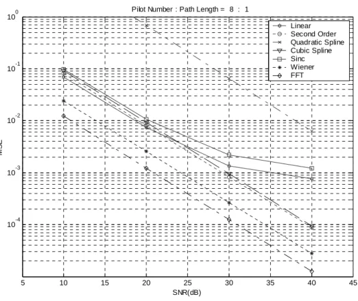
We simulate the previously mentioned channel interpolation techniques assuming channel impulse with exponentially decayed power. The channel taps of our simulation are assumed sam-ple-spaced and pilot allocations are equally spaced. The results are shown in Figure 1.
5 10 15 20 25 30 35 40 45 10-4 10-3 10-2 10-1 100 MS E SNR(dB)
Pilot Number : Path Length = 8 : 1
Linear Second Order Quadratic Spline Cubic Spline Sinc Wiener FFT
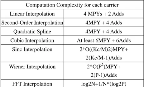
We first notice the quadratic spline interpolation function unexpectedly performs the worst among all. It can be reasonably explained as that when noise added to the pilot-carriers, the noise affects not only the pilot-carrier’s neighborhood but also whole region, due to the reason that we assume the continuity of channel. Similarly, cubic spline technique performs just a little better than the lower-complexity second order interpolation. As for case of longer path lengths, the MSE performance of Wiener interpolation technique performs worse than cubic spline. This can be seen as the effect of model mismatch of channel statistics. In addition to MSE performance, we compare their complexity in Table 1.
Table 1. Comparison of computation complexities of several channel interpolation techniques Computation Complexity for each carrier
Linear Interpolation 4 MPYs + 2 Adds Second-Order Interpolation 4MPY + 4 Adds
Quadratic Spline 4MPY + 4 Adds Cubic Interpolation At least 6MPY + 6Adds
Sinc Interpolation 2*O((Kc/M)2)MPY+ 2(Kc/M-1)Adds Wiener Interpolation 2*O(P2)MPY+
2(P-1)Adds FFT Interpolation log2N+1/N*(log2P)
Considering the MSE performance in Figure 1 and computation complexity in Table 1, we con-clude that the second-order interpolation is effective than in terms of performance and cost. (b) Two new DCT-based channel interpolation methods
When performing DFT on a set of N-point data, it is equivalent to periodically extend the N-point data to infinite length and then transform it by discrete time Fourier transform (DTFT). Therefore, if it is discontinuous between two ends of the N-point data, there will be abrupt varia-tion in between consecutive periods after extension and high frequency component will rise in the transform domain. By the interpolation concept, high frequency component is usually the source of aliasing and must be prevented as much as possible. Therefore, in this case, we have a high tendency of getting error-prone interpolated channel frequency samples, and this is why the esti-mation will be poor by using DFT-based interpolator if the channel has non-sample-spaced path delay times.
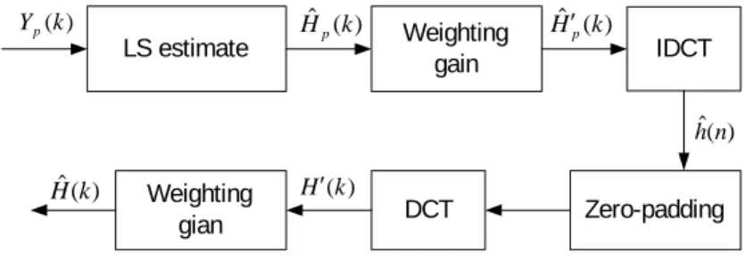
Compared with DFT, DCT can reduce high frequency component in the transform domain by eliminating the edge effect as mentioned above. The reason is that operation of N-point DCT is equivalent to extend the original data to 2N-point by mirror-duplication and then perform 2N-point DFT on the extended data followed by constant magnitude and phase compensation. Obviously, mirror -duplication can solve the discontinuity problem introduced by periodic exten-sion. Therefore, DCT indeed has better power concentration at low frequency. This benefits in-terpolation process. In the following We propose two DCT-based estimators. The first one is DCT/EIDCT-based channel estimator [5] as shown in Figure 2.
LS estimate ) (k Yp Hˆp(k) DCT Zero padding Extendible IDCT ) ( ˆ n hc Hˆ k( )
Figure 2. The 1st new DCT/EIDCT-based channel estimator
The operation of extendible IDCT is
1 , , 2 , 1 , 0 ) 2 1 ( cos ) ( ˆ ) ( ) ( ˆ 1 0 − = ⎟ ⎠ ⎞ ⎜ ⎝ ⎛ + ⋅ =
∑
− = N k m M N k m h m w k H M m c π Lwhere M is the original data length and N is the data length after interpolation.
The second DCT-based estimator is IDCT/DCT-based channel estimator. The block diagram of this estimator is shown in Figure 3.
LS estimate Weighting gain IDCT Zero-padding DCT Weighting gian ) (k Yp Hˆp(k) Hˆ′p(k) ) ( ˆ n h ) (k H ′ ) ( ˆ k H
where the 1st and 2nd weighting gain operations are respectively:
Figure 3. The 2nd new IDCT/DCT-based channel estimator
⎪ ⎩ ⎪ ⎨ ⎧ − ≤ ≤ = = ′ − 1 1 ) ( ˆ 0 ) ( ˆ 2 1 ) ( ˆ 2 H k k M e k k H k H p M k j p p π , ⎪ ⎩ ⎪ ⎨ ⎧ − ≤ ≤ ′ = ′ = 1 1 ) ( 0 ) ( 2 1 ) ( ˆ 2 H k k N e k k H k H N k jπ
Among these two estimators, the DCT/EIDCT-based has better performance. Although IDCT/DCT-based estimator has a little performance degradation, it has the advantage of direct implementation by conventional DCT and IDCT hardware and software.
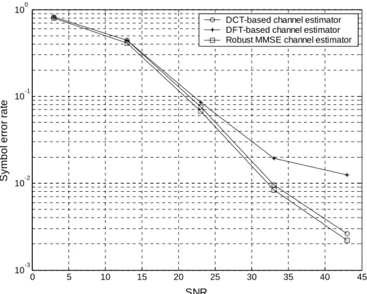
To evaluate performance of the proposed new channel estimator, here we use a channel with non-sample-spaced multipath delay times to simulate the performance of the two estimators. Fig-ure 4 shows the SER of the DCT/EIDCT-based channel estimator, along with the DFT-based es-timator and robust LMMSE eses-timator. We can find that DCT/EIDCT-based has better perform-ance than DFT-based estimator at high SNR and has the performperform-ance close to robust LMMSE estimator. The error floor of DFT-based estimator is due to the aliasing effect. The DCT/EIDCT-based estimator can exactly solve the problem and reduce the error floor. Figure 5 shows the SER performances of IDCT/DCT-based estimator. The performance of IDCT/DCT-based estimator is a little worse than DCT/EIDCT -based estimator but still better than DFT-based estimator. Therefore, for the implementation issue, it’s a good choice.
0 5 10 15 20 25 30 35 40 45 10-3 10-2 10-1 100 SNR S y m b o l e rro r ra te
DCT-based channel estimator DFT-based channel estimator Robust MMSE channel estimator
0 5 10 15 20 25 30 35 40 45 10-3 10-2 10-1 100 SNR S y m b o l e rro r ra te
DCT/EIDCT-based channel estimator IDCT/DCT-based channel estimator DFT-based channel estimator
Figure 4. SER performances of DFT-based and DCT-based channel estimators.
Figure 5. SER performance of IDCT/DCT-based channel estimator
(c) Two new channel estimation methods for fast-fading channels
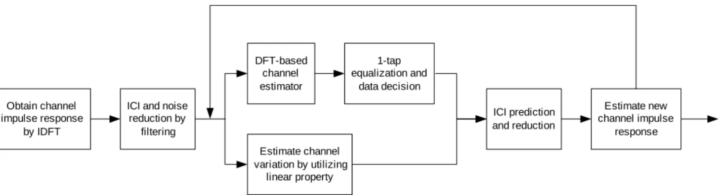
The first fast-fading channel estimation algorithm flow is shown in Fig. 6 and described as follows.
ICI and noise reduction by filtering Obtain channel impulse response by IDFT DFT-based channel estimator 1-tap equalization and data decision Estimate channel variation by utilizing linear property ICI prediction and reduction Estimate new channel impulse response
Figure 6. Block diagram of the proposed fast-channel estimation method The algorithm steps:
1. Assumed i is the symbol index, is the pilot subcarrier, M is the number of pilot
sub-carriers. ) ( , m Yip 0 ), ( ) ( ) ( ) ( ) ( (,0) , ) 0 ( = = = = I m M N Y m Y m Y m Y m Yi i ip ip i
2. Estimate channel impulse response for the i-th symbol by performing IDFT on frequency
responses at pilot subcarriers, which are obtained by 1-tap division
i hˆ 1 , , 2 , 1 , 0 , ) ( ) ( ) ( ˆ )}, ( ˆ { ˆ ) 0 ( , ) 0 ( , ) 0 ( , = = − = m M m P m Y m H m H IDFT ip ip ip i L h
3. To reduce ICI and noise effect on the channel impulse estimate, a smoothing filter or LMMSE can be applied to consecutive symbols [6]. After ICI and noise reduction, estimate
of channel impulse response for the i-th symbol is defined ashˆ(i0).
4. Perform DFT-based channel estimation using . Then use the estimated channel
fre-quency response, , to equalize , i.e.,
) ( ˆ I i h ) ( ˆ m Hi Yi(I)(m) , 0,1,2, , 1 ) ( ˆ ) ( ) ( ˆ ) ( ) ( = = − N m m H m Y m Y i I i I i L .
After that, decisions are made to yield dˆ mi( )
5. For the i-th symbol, the difference between and is used to derive .
. is the estimated channel impulse response for the (i-1)-th
sym-bol, which has been processed by this ICI-reduction algorithm. Then with the assumption
that channel variation during two consecutive OFDM symbols is linear, we can estimate
) ( ˆ I i h ˆ(I1max) i− h sl ) ( 1 ) ( , max ˆ ˆ ˆ I i I i i diff =h −h− h ˆ(I1max) i− h l s
for the i-th symbol by i i i i iM T
s i diff i s s s s N T , ˆ [ˆ ˆ ˆ ˆ ] ˆ =h , × × s = ,0 ,1 ,2 L , −1 s ˆ T 1
bol d
by the number of total samples within a comp
6. With the information of and ICI can be predicted and reduced by perform ng whereTs is the complete OFDM sym uration including cyclic prefix. Then estimate sˆl
of s can be calculated by dividingl hˆdiff ,i lete
OFDM symbol. i sˆ dˆ mi( ), i 1 , , 2 , 1 , 0 , ˆ ) ( ) ( ˆ 1 ) ( ) ( (0) , ) 1 ( = ⎥ ⎢ − ⎜⎜ ⎟⎟ − =
∑
∑
− + m e s k m L k d N m Y m Y j N l i i i I i 1 0 2 − ⎥⎦ ⎤ ⎢⎣ ⎡ ⎠ ⎞ ⎝ ⎛ ≠ − = N m k M l lk L πThen use this ICI-reduced signal to yield new channel impulse response
1 , , 2 , 1 , 0 , ) (m P ) ( ) ( ˆ ) 1 ( , ) 1 ( , = = − + + M m m Y m I p i I p i L
In the performance simulation, we assume 16QAM data. The number of total subcarriers = )}, ( ˆ { ˆ ( 1) , ) 1 ( + = + H m H IDFT iIp I i h
This completes the I-th iteration.
7. End if I = I , otherwise I = I + 1 and repeat Steps 4-7.
N 64, the total bandwidth 500KHz, the sampling periodTc s
max
µ
2
= , and the length of cyclic prefix
T
Tg =4 c . The multipath channel is assumed sample-spaced with ν =4 with exponen-tially-decayed power profile. There are 4 equispaced pilot s
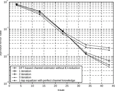
performance for the case with
ubcarriers. Figure 7 shows the SER
04 . 0 = T
fd Imax =3. As shown, the ICI-reduction algorithm effec-tively reduces the error floor.
0 5 10 15 20 25 30 35 40 45 10-3 10-2 10-1 100 S y m b ol er ro r ra te
DFT-based channel estimator without ICI-reduction 1 iteration
2 iteration 3 iteration
1-tap equalizer with perfect channel knowledge
SNR
n method is based on the reasonable assumption that for is less than 0.1, the channel variation over an OFDM symbol can be assumed linear
Figure 7. SER performance of Doppler-induced ICI reduction algorithm, fdT =0.04 The second new fast-fading channel estimatio
T fd
[7], [8], where is the Doppler frequency and T is the OFDM symbol duration. With this
as-e-varia
d f
sumption, the tim nt channel impulse response can be written as
∑
− − + = 1 = ) ( ) ν δ l m l a and DFT of the received signal can be written as
0 ( ) , ( l ln s m n h 1 , , 1 , 0 ) ( ~ ) ( ) ( ) ( 1 ) ( 1 0 2 1 0 1 0 2 − = + + − =
∑ ∑
∑
− = − − = − = − N m m N e a m d e k m L k d s N m Y l N lk j l l N k N lk j l L ν π ν πwhere sl and al are the variation slope and initial value of the path gain, and L(k) is
{ }
⎪ ⎩ ⎪ ⎨ ⎧N(N−1)/2 m=0,±N,±2N,L = = ) sin( 2 ) ( e / otherwise N k jN n DFT k L π jπk NTo solve the channel parameter, by considering the strong correlation between the ICI’s, we first perform the following operations to reduce ICI significantly reduced.
[ ( ) ( 1 )] ( ) ( 1) ~( ) ~( 1) ) ( 1 ) 1 ( ) ( 1 0 ) 1 ( 2 2 1 0 1 0 2 + − + ⎥ ⎥ ⎦ ⎤ ⎢ ⎢ ⎣ ⎡ + − + − + − − = + −
∑ ∑
∑
− = + − − − = − = − m N m N e m d e m d a e k m L k m L k d s N m Y m Y l N m l j N lm j l l N k N lk j l ν π π ν πFrom this set of differential equations, we form a linear system for parameters and . From which we can achieve accurate modeling of fast channel, and accordingly achieve effective channel estimation and demodulation process. Fig. 8 shows the simulation results of the proposed method, in comparison with the method of [9]. As shown the new method has better performance.
l s al 0 5 10 15 20 25 30 35 40 45 10-3 10-2 10-1 100 S y m b o l e rro r ra te
Anastasios Stamoulis' method Modified method 1-tap equalizer
SNR
Figure 8. SER comparison of the method in [9] (4ν pilots) and the new method (3ν pilots), 04 . 0 = T fd
(d) A unified multi-mode and multi-standard SDR baseband inner receiver
Basically the proposed receiver architecture is cost and performance effective, and can be
ted in the original flexibly reconfigured for multi-mode and multi-standard OFDM operations, with low overhead and small area. Due to page limitation, we will not detail the architecture of our design.
IV.
Conclusion
In this project, we generally completed all the tasks originally planned. We have proposed many efficient baseband signal processing techniques for OFDM systems, particularly for channel es-timation. In addition, we also produced some extra new results not commit
ue to page limitation, some more new findings are not covered here, such as those re-ing, we have publish one conference paper in nd submitted two papers to ICC04 and one paper to ICASSP04. Meanwhile, we are i
Refer
[2] Quinney, A simple introduction to numerical analysis:
interpola-[3]
ransform-Domain Processing,” Proc.
[4] T Based
Pi-[6] S. Hammerschmidt, “Channel Estimation for Mobile
[7]
-Division Multiplexing Systems in Time-Variant Multipath Channels,” IEEE Trans.
[8] FDM Systems for
Broadband Mobile Application,” IEEE Comm. Letters, vol. 3, no. 12, pp. 332-334, Dec. 1999.
[9] A. Stamoulis, S. N. Diggavi, and N. A. Dhahir, “Estimation of fast fading channels in OFDM,” IEEE WCNC, vol.1, pp. 465-470, March 2002.
proposal. D
lated OFDM synchronization. As of this writ ICASSP03 a
n the process of writing up the detailed results and submitting them journals.
ences
[1] P. Hoeher, S. Kaiser and P. Robertson, “Two-dimensional pilot-symbol-aided channel esti-mation by Wiener filtering,” ICASSP, Vol: 3, Page(s): 1845 -1848 April 1997
R. D. Harding and D. A.
tion and approximation, Adam Hilger 1989
Y. Zhao and A. Huang, “A Novel Channel Estimation Method for OFDM Mobile Commu-nication Systems Based on Pilot Signals and T
VTC’97, pp. 2089-2094.
B. Yang, K. B. Letaief, R. S. Cheng, and Z. Cao, “Windowed DF
lot-symbol-Aided Channel Estimation for OFDM Systems in Multipath Fading Channels,” Proc. VTC’00-Spring, vol. 2, pp.1480-1484.
[5] Y. F. Hsu and Y. C. Chen, “Rational interpolation by extendible inverse discrete cosine transform,” Electronics Letters, vol. 33, no. 21, pp. 1774-1775, 9 Oct. 1997.
A. A. Hutter, R. Hasholzner, and J.
OFDM Systems,” IEEE VTC’99-Fall, vol. 1, pp. 305-309.
W. G. Jeon, K. H. Chang, and Y. S. Cho, “An Equalization Technique for Orthogonal Fre-quency
Comm., vol. 47, no. 1, Jan. 1999.
![Figure 8. SER comparison of the method in [9] ( 4 ν pilots) and the new method ( 3 ν pilots),](https://thumb-ap.123doks.com/thumbv2/9libinfo/8391629.178729/12.892.268.613.554.828/figure-ser-comparison-method-pilots-new-method-pilots.webp)
