國 立 交 通 大 學
電 控 工 程 研 究 所
碩 士 論 文
效率最佳化之單相無刷直流風扇馬達使用
霍爾感測器或無感測控制
Efficiency Optimization Control for Single-Phase Brushless
DC Fan Motors with or without Hall Sensor
研 究 生:陳煒超
指導教授:鄒應嶼 博士
效率最佳化之單相無刷直流風扇馬達使用
霍爾感測器或無感測控制
Efficiency Optimization Control for Single-Phase
Brushless DC Fan Motors with or without Hall Sensor
研 究 生: 陳煒超 Student: Wei-Chao Chen
指導教授: 鄒應嶼 博士 Advisor: Dr. Ying-Yu Tzou
國立交通大學
電控工程研究所
碩士論文
A Thesis
Submitted to Institute of Electrical and Control Engineering College of Electrical Engineering
National Chiao Tung University in Partial Fulfillment of the Requirements
for the Degree of Master in
Electrical and Control Engineering October 2009
Hsinchu, Taiwan, Republic of China
效 率 最 佳 化 之 單 相 無 刷 直 流 風 扇 馬 達 使 用
霍 爾 感 測 器 或 無 感 測 控 制
研究生:陳煒超 指導教授:鄒應嶼 博士 國立交通大學電控工程研究所 中文摘要 本論文實現效率最佳化之單相無刷直流風扇馬達使用霍爾感測器或無感測控制策 略。本文提出簡單的模型方法並配合適當的參數鑑別,建立符合單相無刷直流風扇馬達 特性的數學模型,其非線性的轉子磁通量分布特色是利用建表的方式來代表。經由電腦 模擬與實際量測結果比對後,可驗證該模型的準確性。本文比較不同的控制策略,包含 開迴路硬換相電壓模式控制、開迴路軟換相電壓模式控制以及閉迴路電流模式控制,分 析其電流波形以及運轉效率的優劣。本文結合閉迴路電流模式控制以及開迴路軟換相電 壓模式控制的優點,配合霍爾感測器輸出訊號的回授,可使單相無刷直流風扇馬達在廣 泛的速度範圍內達到效率最佳化。本論文亦實現高效率且低成本的單相無刷直流風扇馬 達無感測驅動,延伸軟換相的控制方法,調整功率開關的空白時間,使線圈上的電流產 生不連續導通的狀態,偵測其反抗電動勢的零交越點即為電流的換相點。為了解決無感 測啟動的問題,本文配合單相馬達非對稱氣隙的特色,使用特殊的啟動機制,不論轉子 初始位置在哪裡,皆可使馬達往既定的方向旋轉,並以 kick-off 的方式加速馬達,直到 反抗電動勢大小足以提供無感測演算法正確的運作,便可切換到無感測驅動模式。在無 感測驅動下,亦使用閉迴路電流模式的控制方法來提升風扇馬達的運轉效率,而電流命 令 係 利 用 查 表 的 方 式 來 取 代 霍 爾 感 測 器 的 訊 號 。 本 文 使 用 數 位 訊 號 處 理 器 (TMS320LF2407A)驗證所提出控制策略的可行性與性能。實驗結果顯示,在有感測控制 下使用效率最佳化的控制方法,其直流鏈電流的平均值至少有 12%的改善,其相電流的 方均根值至少有 10%的改善,其相電流的峰值至少有 42%的改善;在無感測控制下,可 使風扇馬達穩定啟動並操作在廣泛的速度範圍,而且其運轉效率幾乎與有感測的結果相 同。Efficiency Optimization Control for Single-Phase Brushless DC Fan
Motors with or without Hall Sensor
Student: Wei-Chao Chen Advisor: Dr. Ying-Yu Tzou
Institute of Electrical and Control Engineering National Chiao Tung University
Abstract
This thesis develops efficiency optimization control strategies for single-phase brushless dc (BLDC) fan motors with or without Hall sensor. A simple modeling method with feasible parameter identification is proposed to meet characteristics of single-phase BLDC fan motor. The nonlinear rotor flux distribution is modeled by a look-up table. With simulation assistance, the proposed model has been verified with measurement results. This thesis compares the different control strategies include open-loop voltage-mode control of hard-commutation scheme, open-loop voltage-mode control of soft-commutation scheme, and closed-loop current-mode control scheme, and analyzes the current response and overall efficiency. With the linear Hall sensor feedback, the advantages of current-mode control scheme and soft-commutation scheme are adopted to achieve maximum efficiency over the entire speed range. This thesis also develops a low-cost and high efficiency sensorless control for single-phase BLDC fan motor drives. The proposed scheme detects the back-EMF zero-crossing-point (ZCP) to realize current commutation without Hall sensor. An adjustable blanking time control method is used to ensure correct detection of the ZCP. To overcome the sensorless start-up problem, a specific strategy based on characteristic of asymmetric air gap is developed to ensure the motor running in predefined direction. Then, an open-loop control called kick-off speed up the fan motor to middle-speed where sensorless control algorithm based on the back-EMF can work properly. The closed-loop current-mode control scheme is also applied to improve the overall efficiency. However, the current reference is produced by look-up table to estimate the Hall sensor signal. Experimental implementation has been constructed on a single-chip DSP controller (TMS320LF2407A) to verify the performance and feasibility of the proposed control strategies. When using the control scheme with Hall sensor, experimental results show that there are at least a 12 % reduction for average value of dc-link current, a 10 % reduction for RMS value of phase current, and a 42% reduction for peak value of phase current. When using sensorless commutation control, the fan motor can start-up smoothly and operate under wide speed range, moreover, the overall efficiency is almost the same to the results of control scheme with Hall sensor.
誌 謝
首先要感謝我的老師鄒應嶼教授兩年來的指導,除了專業知識上的啟發之外,也讓 我思考與解決問題的能力有很大的成長。謝謝老師在研究及教學上的督促鼓勵,生活上 的關心,以及學習經驗的分享,相信這些在我以後的生活與工作上都將有極大的助益。 感謝育宗、晏詮與宗罄學長,在這兩年中給我許多的協助,除了課業上的問題外, 也提供我很多寶貴的建議。感謝同窗戰友茗皓、宗翰、哲瑋與家豪昔日的相互扶持與鼓 勵,謝謝你們在這些日子裡的陪伴,一起做研究一起歡樂日子讓人懷念,尤其是武漢研 討會之旅,將會是人生最難忘的回憶之一。謝謝學弟哲瑋、彥勳、甫尊、政江、建成與 智偉,有了你們的加入,讓實驗室充滿朝氣與笑容,也豐富我的研究生活;也希望將來 大家在社會上都能夠很有成就,同時不要忘記我們永遠都是實驗室的夥伴。感謝月貴在 一些行政事務與實驗器材購買上的幫助,減輕了我們許多工作的負擔。 最後要感謝我的父母、弟弟以及所有關心我的長輩,謝謝你們給我的支持與關懷, 願與你們一同分享這份喜悅與榮耀。謹以此論文獻給所有我的長輩與師長們…
陳煒超 2009 秋 於新竹交大Table of Contents
Abstract (Chinese) …..………..…...……... i
Abstract (English)………...……...…..ii
Acknowledgement………..……...….iii
Table of Contents ...iv
List of Tables………...….. vi
List of Figures ...vii
Chapter 1 Introduction………...… 1
1.1 Research Background and Recent Development………...…... 1
1.2 Research Motivation and Objectives………..……..……... 4
1.3 Thesis Organization... 6
Chapter 2 Basic Operation of Single-Phase BLDC Fan Motors……….. 7
2.1 Structure of Single-Phase BLDC fan motors………... 7
2.2 Mathematical Modeling…...…….……...10
2.3 Parameter Identification...12
2.3.1 Electrical Parameters………..………... 12
2.3.2 Mechanical Parameters……...………...14
2.4 A Study of Dynamic Behavior... 17
2.4.1 Basic Operation Principle………... 17
2.4.2 Analyses of Steady-State Response…...………18
2.4.3 Verification of Proposed Model……….……….…....…...23
Chapter 3 Efficiency Optimization of Single-Phase BLDC Fan Motor Drives…... 27
3.1 PWM Control Strategies…... 27
3.1.1 PWM Switching Scheme 1……….……...………28
3.1.2 PWM Switching Scheme 2……….……...………35
3.1.3 PWM Switching Scheme 3……….……...………37
3.1.4 PWM Switching Scheme 4……….……...………39
3.2 Open-Loop Voltage-Mode Control of Soft-Commutation Scheme…... 42
3.3 Efficiency Optimization Control Scheme.……...………... 47
3.3.1 Principle of Efficiency Optimization.…..………. 47
3.3.2 System Configuration.……..………. 48
3.3.4 Analyses of Simulation Results………...……….. 57
Chapter 4 Sensorless Control for Single-Phase BLDC Fan Motor Drives ... 63
4.1 Sensorless Control Scheme……... 63
4.1.1 Basic Operation Principle……..………..…….…. 63
4.1.2 Zero-Crossing Point Detection…...………...…………..….… 66
4.2 Sensorless Start-Up Strategy... 67
4.2.1 Starting Method based on Asymmetric Air Gap ……….………. 67
4.2.2 Start-Up Procedure………...………....…. 70
4.2.3 Open-Loop Voltage-Mode Control without Hall sensor………....…... 72
4.3 Closed-Loop Current-Mode Control of Sensorless Motor Drives... 76
4.3.1 System Configuration……….………….…....…. 76
4.3.2 Analyses of Simulation Results………...………..…..….. 78
Chapter 5 Laboratory Setup and Implementation of Single-Phase BLDC Fan Motor Control System……….... …82
5.1 Laboratory Setup ……….. 82
5.2 Software Implementation………... 84
5.3 Analyses of Experimental Results……...87
5.3.1 Commutation Control with Hall Sensor……...…..87
5.3.2 Sensorless Commutation Control………….………. 99
Chapter 6 Conclusions ...105
6.1 Conclusions………...………..105
6.2 Future Works………...107
References ...108
List of Tables
1.1 Functions of commercial drive IC... 2
2.1 Parameters of the tested motor ... 16
3.1 Parameters and operation conditions for calculating power losses. ... 35
List of Figures
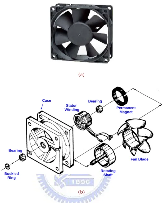
2.1 Structure of the single-phase BLDC fan motor (a) real motor configuration
and (b) exploded perspective view ... 8
2.2 Cross-sectional view of stator and rotor assembly with asymmetric air gap ... 8
2.3 Operational principle of Hall sensor ... 9
2.4 Schematic of the full-bridge inverter and equivalent modeling for a single-phase BLDC fan motor... 11
2.5 Block diagram for modeling of the single-phase BLDC fan motor ...12
2.6 Step voltage input and current response. ... 14
2.7 The table of rotor flux distribution versus rotor position ...14
2.8 Speed response from stop to rotate... 16
2.9 The open-loop voltage-mode control of hard-commutation scheme (a) the schematic of commutation control circuit and (b) operation waveform ... 18
2.10 Steady-state current response when using open-loop voltage-mode control of hard-commutation scheme ... 19
2.11 Steady-state torque response when using open-loop voltage-mode control of hard-commutation scheme... 20
2.12 Equivalent dc-bus model of power stage... 22
2.13 Steady-state response of dc-bus current ...23
2.14 Simulation results with the open-loop voltage-mode control of hard-commutation scheme under (a) duty = 100%, (b) duty = 80%, and (c) duty = 50% ... 24
2.15 Phase current comparison between simulation result and experiment measurement (a) duty = 100%, (b) duty = 80%, (c) duty = 50%, and (d) duty = 20% ...25
2.16 The RMS value of phase current and rotor speed curves under different duty ratios ... 26
3.1 Switch configuration of motor drives... 28
3.2 (a) PWM switching scheme 1 and (b) macro view of switching pattern. ... 28
3.3 Model of transistor’s characteristic ...30
3.4 Conducting current of transistor S2 and S4...30
3.5 Conducting current of transistor S1 and S3...31
3.8 Conducting current of diode D2 and D4. ... 34
3.9 Pie chart of total power losses for PWM switching scheme 1. ... 35
3.10 (a) PWM switching scheme 2 and (b) macro view of switching pattern. ... 37
3.11 Pie chart of total power losses for PWM switching scheme 2. ... 37
3.12 (a) PWM switching scheme 3 and (b) macro view of switching pattern. ... 39
3.13 Pie chart of total power losses for PWM switching scheme 3 ... 39
3.14 (a) PWM switching scheme 4 and (b) macro view of switching pattern ... 41
3.15 Pie chart of total power losses for PWM switching scheme 4 ... 41
3.16 The operation waveform for open-loop voltage-mode control of soft-commutation scheme... 43
3.17 The steady-state waveforms when using soft-commutation scheme with different blanking times at 4000 RPM (a) no blanking time, (b) blanking time of 10% commutation cycle, and (c) blanking time of 15% commutation cycle... 44
3.18 The equivalent circuit after turning off the switches... 46
3.19 The steady-state waveforms when using soft-commutation scheme (a) 3000 RPM with blanking time of 10% commutation cycle and (b) 1000 RPM with blanking time of 5% commutation cycle... 46
3.20 Architecture of closed-loop current-mode control system. ... 49
3.21 Current multiplier control scheme with linear Hall sensor feedback ... 49
3.22 The current response when motor is standstill………. .……….. 50
3.23 The operation principle of single-update-mode triangular-carrier modulator…...……….. 51
3.24 The general digital PWM modulator………. ... .……….. 53
3.25 Frequency response of GPWM(s)………. ...……….. 53
3.26 Block diagram of current-loop control………. ... .……….. 54
3.27 The continuous time equivalent of current-loop control system ... 55
3.28 Block diagram of digital PI controller... 57
3.29 Loop gain frequency response with PI(s) and PI(z) ... 59
3.30 Simulation result of step response at operation point of 250 mA ...59
3.31 Simulation results of steady-state response based on closed-loop current-mode control scheme (a) 4000 RPM, (b) 3000 RPM, (c) 1000 RPM, and (d) 500 RPM ...61 3.32 The current-loop controller enters the limit region if the fan motor is over
4000 RPM... 62
3.33 If the fan motor accelerates over 4000RPM, the control system switches the control mode ... 62
4.1 Operation waveform of sensorless control method ... 65
4.2 Three possible relationships between the phase current and the back EMF ... 65
4.3 Operation waveform for back-EMF ZCP detection. ... 66
4.4 Two possible rotor positions when motor is standstill ... 68
4.5 Motor state while positive current pulse is supplied at Position 1 ...69
4.6 Motor state while positive current pulse is supplied at Position 2 ...69
4.7 Motor state while negative current pulse is supplied at Position 1 ...69
4.8 Motor state while negative current pulse is supplied at Position 2. ...70
4.9 Sensorless start-up control steps for single-phase BLDC fan motors (a) inverter circuit and (b) control steps... 71
4.10 Speed response during sensorless start-up procedure ...72
4.11 Block diagram of open-loop voltage-mode sensorless control for single-phase BLDC fan motor... 73
4.12 Sensorless start-up control from standstill to 4000 RPM ... 73
4.13 Simulation results of sensorless control at 4000 RPM (a) steady state waveforms of phase current and phase voltage and (b) Non-excited voltage sampling and ZCP detection... 74
4.14 Sensorless start-up control from standstill to 1000 RPM. ... 75
4.15 Simulation results of sensorless control at 1000 RPM (a) steady state waveforms of phase current and phase voltage and (b) Non-excited voltage sampling and ZCP detection... 76
4.16 Block diagram of sensorless control system with closed-loop current-mode control...77
4.17 Current multiplier control scheme with estimated Hall sensor by look-up table. ... 77
4.18 Simulation results of current-loop control at different speed operation (a) 4000 RPM, (b) 3000 RPM, (c) 1000 RPM, and (d) 500 RPM... 80
4.19 Statistics curves for different control schemes (a) RMS value of phase current and (b) peak value of phase current. ... 81
5.1 Schematic of the prototype control system for single-phase BLDC fan motor...83
5.3 Interrupt configuration in the DSP controller... 85 5.4 Program flow chart for control algorithms (a) drive with Hall sensor (b)
drive without Hall sensor... 86 5.5 Overall functional block diagram of the single-phase BLDC fan motor
control system... 86 5.6 Steady-state response when using the open-loop voltage-mode control of
hard-commutation scheme (a) 4000 RPM, (b) 3000 RPM, and (c) 1000 RPM... 89 5.7 Steady-state response when using the soft-commutation control scheme (a)
4000 RPM, (b) 3000RPM, and (c) 1000 RPM ... 90 5.8 Step response at zero current (a) 400 mA step input and (b) 240 mA step
input ... 91 5.9 Steady-state response of closed-loop current-mode control scheme at 3000
RPM (a) Hall sensor and phase current and (b) current reference and response ... .92 5.10 Steady-state response of closed-loop current-mode control scheme at 1000
RPM (a) Hall sensor and phase current and (b) current reference and response ... 93 5.11 Steady-state response of closed-loop current-mode control scheme at 500
RPM (a) Hall sensor and phase current and (b) current reference and response ... 94 5.12 When the fan motor over 4000 RPM, the working mode switches from
current-loop control to soft-commutation control ... 95 5.13 Statistics curves of various control schemes (a) average value of dc-link
current versus rotor speed, (b) RMS value of phase current versus rotor speed, and (c) peak value of phase current versus rotor speed... 96 5.14 Percentage improvement for two methods (a) average value of dc-link
current (b) RMS value of phase current, and (c) peak value of phase current. ...97 5.15 Compare commercial IC with proposed control scheme (a) RMS value of
phase current and (b) peak value of phase current. ... 98 5.16 ZCP detection procedure at 3000 RPM... 99 5.17 Steady-state response of closed-loop current-mode sensorless control (a)
3000 RPM, (b) 2000 RPM, (c) 1000 RPM, and (d) 500 RPM... 101 5.18 Sensorless start-up procedure (a) toward 3000 RPM and (b) toward 1000
5.19 Statistics curves of various control schemes (a) average value of dc-link current versus rotor speed, (b) RMS value of phase current versus rotor speed, and (c) peak value of phase current versus rotor speed... 104
Chapter 1
Introduction
1.1
Research Background and Recent Development
With fast advance in technology, it is essential for the electronic products to be elaborated and sophisticated, and the internal functions are various and high speed. A common problem associated with modern electronic product is forced air cooling. The easiest way with low cost for forced air cooling is brushless dc (BLDC) fan motor installations. The phase windings of BLDC fan motor can be categorized as single-phase or three-phase, their flux distribution can be either sinusoidal or trapezoidal. The three-phase BLDC fan motors have the characteristics of high ratio of torque to weight, low noise, fast response, high efficiency and easy maintenance. However, it is an involved and costly process to fabricate the three-phase motor and it needs more requirements for six switches of inverter and three Hall sensors. For simple structure and requirement of single-phase BLDC fan motor, it’s easy to employ to slim type application of consumer electronics. Moreover, due to the characteristics of wide speed range, small size, easy controllability, and long lifetime expectancy, single-phase BLDC motors are now the major choice for forced air cooling in PC, NB, and other information appliances.
With rapidly development of integrated circuit, the integration of control and drive ICs have been widely implemented in fan motors. Taking PCs for example, there are many inside devices such as power supply, CPU, and video graphic array (VGA) card, etc. Each device usually combines with single-phase BLDC fan motor and its drive IC. Based on International Data Corporation (IDC) research, the worldwide shipment of PC is over 150 million units in
2008. It tells that the small size single-phase BLDC fan motors have significant market potential, and development in motor drive IC will become a major trend. Many single-phase BLDC fan motor drive ICs have been commercialized such as LB11961 of Sanyo, BD6964FVM of Rohm, THMC45 of Texas Instruments, and APX 9262 of Anpec, etc. The functions of commercial drive IC list in Table 1.1. Among them, LB11961 has the feature of build-in variable speed function controlled by voltage of thermal resistor, that is, the fan motor speed is varied with environment temperature. The overall efficiency improvement is based on soft-commutation scheme to reduce the current spike at commutation boundary. The additional functions of rotor locked detection and auto-restart are used to protect the motor if the rotor is unexpected stop. These low cost and high performance drive ICs give the system host a new solution for air cooling.
TABLE 1.1
Functions of commercial drive IC
Sanyo Rohm TI Anpec LSI Melexis UTC
Lock Detection &
Auto-Restart ◎ ◎ ◎ ◎ ◎ ◎ ◎ Lowest Speed Setting Pin ◎ PWM Control ◎ ◎ ◎ ◎ ◎ ◎ ◎ Soft-Start ◎ ◎ Soft-Commutation PWM ◎ ◎ ◎ ◎ Current Protection ◎ ◎ ◎ ◎ ◎ ◎ ◎
Most commercial single-phase BLDC fan motor drive ICs utilize an open-loop voltage-mode control of hard-commutation scheme with full-bridge circuitry to realize variable speed control, and the commutation control is accomplished via a linear Hall sensor [1]-[3]. However, such method is disadvantageous for current spikes at commutation boundary, which
increasing power circuit rating. There are many methods to compensate for these effects. One method is by advancing the Hall sensor position so that commutation takes place before the current reach too high [4]. Nevertheless, it is inconvenient to modify Hall sensor position which is often installed on drive PCB. Another method called soft-commutation is employed to reduce the current spikes by modifying the switching patterns of inverter [5]-[6]. However, the overall efficiency is improved only for high speed. The above methods still can not remove the root problem of current spike at commutation boundary, so the overall efficiency will be seriously degraded in wide speed control applications.
The linear Hall sensor provides the information of rotor position and velocity via signal processing technique. However, there are some disadvantages such as additional installation of the sensor, signal conditioning circuit, sensitive to magnetic noises, and unsuitable for high temperature environment. To prevent the above problems, many sensorless techniques are presented to develop reliable and low cost control strategies for BLDCMs, which can be generally classified into two categories [7]. The first type is based on back-EMF sensing [8]-[10]. Since the back-EMF voltage is the function of the rotor position, the most common approach is to extract the rotor position from the unexcited phase. However, these methods are not suitable for single-phase BLDC fan motor because of no unexcited phase and low signal-to-noise ratio (SNR) of the measured signals at low speed operation. The second type is to derive the rotor position with a mathematic motor model by measuring the phase voltage and current. By using these quantities, the rotor position can be determined using a state observer, or a Kalman filtering technique, or by direct calculations [11]-[12]. These methods are computationally intensive, and large rotor position detection errors may occur because of quantization and truncation errors, and measurement inaccuracies. Besides, the estimation performance is affected with some motor parameters varying with thermal or operation conditions. It also suffers the low SNR of the measured signals at low-speed operations.
A common problem associated with the sensorless motor drive system is its starting performance. Using above sensorless algorithms, the measured signal is too small to make precise position estimation when motor is at standstill or low speed. The most common solution to the problem is the open-loop start-up method from a pre-determined rotor position [13]. The permanent magnet rotor will align to the direction corresponding to the induced magnetic filed. With a known initial rotor position, an open loop control with ramp up frequency of injecting current is applied to speed up the motor from standstill. However, especially for the single-phase BLDC fan motor, it has only single phase winding, so the induced stator field is just two opposite directions. The motor may start to rotate in company with temporary reversing rotation or even unable to startup. Another starting method is the initial rotor position estimation which is based on the saturation effect of stator iron core due to the permanent magnet [14]. Reference [15] detects the initial rotor position by the time periods of discharge of stator windings, which are excited before discharge. Nevertheless, such methods have drawbacks being complicated or have to sense the current and voltage.
1.2 Research Motivation and Objectives
The research objectives of this thesis are in three-folds. The first one is to introduce a simple modeling method with feasible parameter identification to meet the characteristics of single-phase BLDC fan motors [16]-[20]. The constructed mathematical model of the highly nonlinear single-phase BLDC fan motor makes it easier for developing more sophisticated control schemes and analyzing the system performance. Simulation results can be verified with measurement results to confirm the validity of propose model.
The second objective of this research is to develop an efficiency optimization control scheme over the entire speed control range. This can be achieved by two aspects, one is choosing an appropriate PWM control strategy and another is increasing the utilization ratio
of driving current. To reduce the power losses in the inverter, the characteristics and the relative advantages and drawbacks of different PWM switching schemes are compared [21]-[23]. To increase the motor output power, this research adopts the closed-loop current-mode control for low and middle speed [24]-[27]; and switch to open-loop voltage-mode soft-commutation control for high speed operation. On the other hand, as the performance of digital signal processors has increased rapidly during last decade, the interest for digital motor control has grown. So, the digital current-loop controller design and consideration are also introduced [28]-[31].
The third objective of this research is the implementation of a low cost and high efficiency sensorless control for single-phase BLDC fan motor drives. The sensorless control scheme extends the soft-commutation method which will ensure the correct detection of the back-EMF zero-crossing point (ZCP) [32]-[35]. In order to promote the overall efficiency, the closed-loop current-mode control scheme is also applied to the sensorless control system. The current reference is produced by look-up table to estimate the linear Hall sensor. A specific sensorless start-up strategy is realized based on the feature of asymmetric air gap to ensure the motor running in predefined direction no matter where the initial rotor position is [36]-[38]. Then, an open-loop control called kick-off speed up the fan motor to middle-speed where sensorless control algorithm based on the back-EMF can work properly.
With the rapidly development of integrated circuit, digital motor control systems have been widely implemented with software based on microcontrollers or digital signal processors (DSPs). These approaches provide flexibility and are suitable for motor drive applications. The proposed control schemes have been implemented on a single-chip DSP controller (TMS320LF2407A) to verify the performance and feasibility for single-phase BLDC fan motors. Experimental verification has been carried out on a single-phase BLDC fan motor control system.
1.3 Thesis Organizations
The thesis is organized as follows. The simple modeling method with illustrated parameter identification and the basic operation principle for single-phase BLDC fan motors are proposed in Chapter 2. Simulation results can be verified with measurement results to confirm the validity of proposed model.
In Chapter 3, the design and realization of efficiency optimization control scheme for single-phase BLDC fan motors with linear Hall sensor is presented. This research adopts the advantages of closed-loop current-mode control scheme and soft-commutation control scheme to achieve efficiency optimization over entire speed control range. The overall efficiency can be compared by various control schemes based on calculation of RMS value and peak value of phase current. The detailed description will be discussed in this chapter.
In Chapter 4, a low cost and high efficiency sensorless control system for single-phase BLDC fan motors is implemented. Using the ZCP detection of back-EMF, the driving current can be commutated without Hall sensor. Besides, due to the feature of asymmetric air gap, a specific starting strategy is employed to start-up the fan motor from standstill to full speed. The detailed description of the sensorless technique, starting procedure and simulation results of system response will be discussed in this chapter.
In Chapter 5, the laboratory setup of the single-phase BLDC fan motor control system with or without Hall sensor is introduced, and the DSP-based software implementation issues are discussed. The overall performance of the proposed control schemes are verified through extensive real-time experimental results. Some concluding remarks and suggested future works related to this research are summarized and discussed in Chapter 6.
Chapter 2
Basic Operation of Single-Phase BLDC Fan
Motors
2.1
S
TRUCTURE OFS
INGLE-P
HASEBLDC
F
ANM
OTORSAmong the numerous types of fan motors, single-phase BLDC motors are now the major choice for forced air cooling applications. Fig. 2.1(a) is the configuration of single-phase BLDC fan motor which is usually an additive device for CPU or power supply to keep from overheating. Fig. 2.1(b) is an exploded perspective view of fan motor and it can be seen that the fan motor comprises a fan case which is provided to cover the fan blades, the container which supports the rotating shaft of the fan, and ball bearings which are inserted into the motor body. Moreover, the magnetic part covers the fan blades from outside and an annular permanent magnet inserts into the inner border.
The distinctive feature of the single-phase BLDC motor is the asymmetric air gap to eliminate dead point. If dead point, where the developed torque value is zero, exists in single-phase BLDC motors, there is a possibility that the motor will stop at the dead-point and be unable to start. Fig. 2.2 shows the cross-sectional view of stator and rotor assembly with asymmetric air gap. A four poles and external-rotor type of single-phase BLDC fan motor is used in this paper. The fan motor is wound with a single coil and the winding terminals are connected to an inverter which is switched at a frequency corresponding to rotor velocity.
(a) Case Bearing Permanent Magnet Fan Blade Rotating Shaft Buckled Ring Bearing Stator Winding (b)
Fig. 2.1. Structure of the single-phase BLDC fan motor (a) real motor configuration and (b) exploded perspective view.
N S N S N S N S N S N S Rotor Stator
Asymmetric air gap
The electronic commutation for a single-phase BLDC fan motor is accomplished by controlling the inverter to excite the corresponding current. Since the torque production performance largely depends on the phase relationship between excitation current and back-EMF, a reliable and accurate rotor position sensing device is required. The rotor position sensing can be achieved by the use of Hall sensors for low-cost applications, or by resolvers and optical encoders for high-performance applications. In practice, Hall sensors are the most widely used for electronic commutation of BLDCM drives. The operational principle of Hall sensor is shown in Fig. 2.3. When a magnetic field is applied to a semiconductor carrying with a constant current IH, a voltage which is proportional to the applied magnetic field will
be generated. The directions of the applied magnetic field, the current flowing, and the Hall voltage are perpendicular. In general, Hall sensors have a number of advantages, including the capability of operating at frequencies in excess of 100 kHz, high reliability, and low cost. However, Hall-effect sensors are sensitive to the temperature due to their physical characteristics, and can not be used at high-temperature conditions.
Electrode Flux VH E IH l d W B θ
2.2
M
ATHEMATICALM
ODELINGThe BLDCMs, along with an appropriate power converter and either speed or position feedback, have become popular in many sophisticated control applications. The proper design and compensation of such system requires an accurate mathematical model with all of the components of the system. This research proposes a simple modeling method to meet the characteristics of single-phase BLDC fan motor, and to investigate both static and dynamic relationship between the driving circuit and the real motor [16]-[19]. By way of proposed model, it will assist designers to analyze the system performance and make the design work more practical.
Fig. 2.4 shows the schematic of the full-bridge inverter and equivalent modeling for a single-phase BLDC fan motor. The stator winding can be modeled as a winding resistance in series with a winding inductance and a back-EMF voltage. The voltage equation describing the dynamic behavior of single-phase BLDC fan motor is given as follow
emf s s iR v dt di L v= + + (2-1)
where v and i are the phase voltage and phase current, respectively. Rs and Ls are the winding
resistance and the winding inductance, respectively. vemf is the back-EMF voltage induced by
rotor flux variation and the value is proportional to motor speed. r
E emf K
v = ⋅ω (2-2)
where ω is the rotor velocity and Kr E is the back-EMF constant which is associated with the
form of nonlinear flux distribution in this application. So, equation (2-2) can be revised as
r e f emf K
v = ⋅φ (θ )⋅ω (2-3)
where K is constant and φf is the normalized value of flux distribution which is varied with rotor position θe.
i
S1 S3 S2 S4V
DCL
sR
sv
emfFig. 2.4. Schematic of the full-bridge inverter and equivalent modeling for a single-phase BLDC fan motor.
The energy transforms from electrical system to mechanical system can be expressed as i
K
Te = T⋅ (2-4)
where KT is the torque constant and is equivalent to the back-EMF constant KE. As mention
before, KT and KE are function of rotor position due to the flux distribution. However, for
single-phase BLDC fan motor, it’s inadequate to represent the nonlinear flux distribution with simple equation. For this reason, building up the table in term of flux distribution is necessary to confirm accuracy of the equivalent model.
For the mechanical system, the developed torque must overcome the inertial acceleration torque, friction torque and the load torque. Therefore, the torque-speed characteristics can be formulated as L r m r m e B T dt d J T = ω + ω + (2-5)
where the inertial acceleration torque is represented by the product of the moment of inertia
Jm and the angular acceleration dωr/dt. The load torque referred to the motor shaft and fan
blade, while the friction torque is the product of the rotor velocity and viscous friction coefficient Bm.
Inverter PWM Commutation Control -+ + -+ + -Hall Sensor H va v b
Flux Distribution Table vab s R s L s 1 m J m B L T r ω e θ s 1 T K E K s 1 emf v f φ f φ i L φ Te ddtωr e θ ω L T 2 r L K T = ω
Fig. 2.5. Block diagram for modeling of the single-phase BLDC fan motor.
According to previous equations, the modeling of the single-phase BLDC fan motor can be represented by a block diagram as shown in Fig. 2.5. The motor is fed with a high frequency PWM voltage by a voltage-source full-bridge PWM inverter. The corresponding output voltage is applied to the motor winding, and then the electromagnetic torque is produced to rotate the fan motor. It should be noted that the value of KE and KT is obtained
from flux distribution table depending on rotor position which is derived by integration of rotor velocity. The output signal of the linear Hall sensor is proportional to rotor flux density and is also characterized by a rotor flux distribution table.
2.3
P
ARAMETERI
DENTIFICATION2.3.1 Electrical Parameters
After the mathematical modeling of the single-phase BLDC fan motor is constructed, the precise parameter identification will improve the consistence to a real motor. Because of single coil, the electrical parameter identification includes winding resistance Rs, winding
inductance Ls and back-EMF constant KE. The resistance and inductance determine the
electrical time constant for dynamic current response. The back-EMF constant is associated with developed torque and speed range of motor.
Usually, the resistance and inductance can be measured by R-L-C meter. However, there is another method which injects a step voltage into the stator winding and observes the current response to extract the parameters. Under this condition, the fan motor should be keep standstill to avoid the interference of the back-EMF voltage, and then the phase winding terminal is injected a step voltage
) ( )
(t V u t t0
v = ⋅ s − . (2-6)
Fig. 2.6 shows the current response which is similar to a first-order R-L series circuit,
) ( ) 1 ( ) ( 0 ) ( 0 t t u e R V t i L t t s R s s s − ⋅ − = − − (2-7) s ss R V i = (2-8) s s R L = τ . (2-9)
From (2-8) and (2-9), the series resistance Rs can be determined by steady state current iss, and
the series inductance Ls can be determined by time constant τ and transient time tss-t0.
Based on (2-2) and (2-3), the back-EMF constant KE is the amplitude of back-EMF
voltage per rotation speed, and it can be obtained from sensing back-EMF voltage and rotor velocity. The back-EMF voltage can be measured by forcing the motor to run at high speed and then release the motor to free running. The measured terminal voltage can be used for the identification of back-EMF constant as well as the table of rotor flux distribution which is shown in Fig. 2.7.
t V i(t) v(t) t0 0 s R V tss
Fig. 2.6. Step voltage input and current response.
0 100 200 300 -1.5 -1 -0.5 0 0.5 1 1.5
Electrical Angle (degree)
N o rm aliz e d F lux D is tribu ti on
Fig. 2.7. The table of normalized flux distribution versus rotor position.
2.3.2 Mechanical Parameters
The interaction of stator field with the rotor field creates an electromagnetic torque. According to (2-4) and (2-5), the fan motor speed response is directly related to mechanical parameter. When fan motor rotates at stable speed, i.e., dωr/dt is zero, then (2-5) can be
revised to L r m T i B T K ⋅ = ω + . (2-10)
Due to mechanical structure of fan motor, the load torque is proportional to the square of fan motor speed, i.e.,
2 r L
T =α⋅ω (2-11)
where α is constant which is related to mechanical structure of fan motor. Therefore, the torque-speed function at stable speed becomes
2 r r m T i B K ⋅ = ω +αω . (2-12)
The least square method is used to derive the viscous coefficient Bm and constant α . It
assumes that the best-fit curve of a given type which has the minimal sum of the square error from a given set of data. With different rotor velocity and corresponding RMS value of phase current, (2-12) can be revised to
⎥ ⎦ ⎤ ⎢ ⎣ ⎡ ⎥ ⎥ ⎥ ⎥ ⎥ ⎦ ⎤ ⎢ ⎢ ⎢ ⎢ ⎢ ⎣ ⎡ = ⎥ ⎥ ⎥ ⎥ ⎦ ⎤ ⎢ ⎢ ⎢ ⎢ ⎣ ⎡ ⋅ ⋅ ⋅ m n n n T T T B i K i K i K α ω ω ω ω ω ω 2 2 2 2 1 2 1 2 1 M M M . (2-13)
According to the least square method, given a system of equations
b x= A (2-14) where ⎥ ⎥ ⎥ ⎥ ⎥ ⎦ ⎤ ⎢ ⎢ ⎢ ⎢ ⎢ ⎣ ⎡ = n n A ω ω ω ω ω ω 2 2 2 2 1 2 1 M M , ⎥⎥ ⎥ ⎥ ⎦ ⎤ ⎢ ⎢ ⎢ ⎢ ⎣ ⎡ ⋅ ⋅ ⋅ = n T T T i K i K i K M 2 1 b , ⎥ ⎦ ⎤ ⎢ ⎣ ⎡ = m B α x . (2-15)
It cannot expect in general to find a vector x for which xA equals b. Instead, it can look for a vector xˆ for which xA is closet to b. So, there is a unique solution
( )
b, that is, xˆ satisfies the minimal sum of square error. Therefore, the viscous coefficient Bm
and constant α can be obtained by (2-16).
Eventually, the remainder is the moment inertia of the fan motor. During the fan motor accelerates from stop to rotate as shown in Fig. 2.8, the rotor velocity can be calculated by linear Hall sensor, and the acceleration dωr/dt can also be approximately estimated. Based on
(2-5) and along with viscous coefficient Bm and constant α , the moment inertia of fan motor
can be derived. Following the above parameter identification methods, the single-phase BLDC fan motor’s parameters list in Table 2.1.
t
t
0
0
dt
d
ω
r)
(t
rω
rω
Fig. 2.8. Speed response from stop to rotate.
TABLE 2.1
Parameters of the tested motor
Single-phase brushless dc fan motor
Type 4 poles Rated voltage 12 V Stator resistance 9.3 Ω Stator inductance 5.6 mH Back-EMF constant 1.82 mV/rpm Rotor inertia 1.6×10⁻⁶ kg⋅m2 Viscous coefficient 1.3×10⁻⁶ N⋅m⋅s/rad
2.4
A
S
TUDY OFD
YNAMICB
EHAVIOR2.4.1 Basic Operation Principle
Due to the flux distribution varies with rotor positions, the magnetic field produced from stator winding should synchronize with rotor field. Fig. 2.9(a) shows the schematic of the commutation control circuit for the single-phase BLDC fan motor with Hall sensor feedback [1]-[3]. The full-bridge inverter consists of four switches S1 to S4 which were controlled to supply required direction of driving current. Each switch connects with anti-parallel diode to remain driving current during the current commutation. Each winding terminal is connected to a pair of switches as shown. When both switches in the same phase are on, the bus voltage is short circuit. This condition should be inhibited at all times. To eliminate short circuit during switching transients, a small dead-time is introduced in between turn-off of one switch and turn-on of the other switch in the same phase.
A linear Hall sensor is fixed to a on drive PCB of the single-phase motor, and biased by a constant voltage. The linear Hall sensor produces an output signal which is proportional to the intensity of the induced rotor field, so it is used to provide rotor position and velocity feedback information via signal processing technique. Fig. 2.9(b) shows the operation waveform based on open-loop voltage-mode control of hard-commutation scheme. The control system accepts the Hall sensor feedback and determines the switching status to commutate the phase current. The phase winding will be conducted 180 electrical degrees for both positive and negative driving current. When the Hall sensor waveform goes through zero from negative to positive transistors S1 and S4 are switched ON and switches S2 and S3 are switched OFF, while when the Hall sensor waveform goes through zero from positive to negative switches S2 and S3 are switched ON and switches S1 and S4 are switched OFF. In other words, transistors S1, S4 and the transistors S2, S3 are complementarily turned ON/OFF to change the directions of the driving current whereby the single-phase motor is revolved.
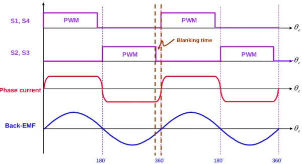
S1 S3 S2 S4 VDC Hall sensor Single-Phase BLDC Fan motor Commutation Logic and PWM Control DIR PWM Cdc (a) PWM Hall sensor PWM PWM PWM S1, S4 S2, S3 e θ e θ e θ e θ 180° 360° 180° 360° Commutation signal (b)
Fig. 2.9. The open-loop voltage-mode control of hard-commutation scheme (a) the schematic of commutation control circuit and (b) operation waveform.
2.4.2 Analyses of Steady-State Response
Fig. 2.10 is the steady-state current response when using open-loop voltage-mode of hard-commutation scheme. There is a significant current spike at commutation boundary. The dynamic behavior of current response is given as follow
) 1 ( ) ( t L R s emf s s e R v v t i = − − − (2-17)
Phase current (A) Back-EMF (V) Torque (N.m) Current spike Diode conduction interval Negative torque
Fig. 2.10. Steady-state current response when using open-loop voltage-mode control of hard-commutation scheme.
where v is the input voltage of phase winding. Rs and Ls are the series resistance and the series
inductance of stator winding, respectively. vemf is the back-EMF induced by rotor flux
variation. Owing to the back-EMF seriously drops at commutation boundary, and it results in a great rising slope of current response, that is the current spike. Moreover, due to the winding inductance, the polarity of the phase current cannot be changed instantaneously, so the current will pass through the anti-parallel diode and decrease to zero at commutation boundary. It results in the driving current out of phase with back-EMF and a negative torque is generated, and consequently the overall efficiency is seriously degraded in wide speed control applications for single-phase BLDC fan motors.
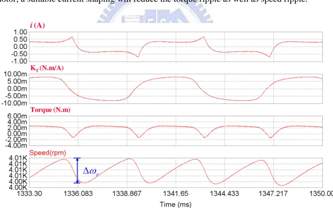
Because of non-linear flux distribution, there are obvious torque ripples during motor revolution [20]. This will result in undesirable effects such as speed ripple and acoustic noise. As commonly known, it is better to achieve constant torque for smooth revolution, which requires very high current to compensate the weak magnetic field at commutation boundary. However, such high current will reduce the overall efficiency and increase the power circuit
rating. Fig. 2.11 shows the steady-state torque response at 4000 RPM. From (2-4) and (2-5), the developed torque can be revised as
L r m r m e av dt B T d J T T +Δ = ω + ω + (2-18)
where Tav is the average torque and ΔTe is the torque ripple. So, the corresponding speed
ripple can be calculated by
m e r J t T ⋅Δ Δ = Δω . (2-19)
From (2-19), the speed ripple is proportional to the torque ripple which is related to the flux distribution and phase current waveform. For the same model of single-phase BLDC fan motor, a suitable current shaping will reduce the torque ripple as well as speed ripple.
r
ω
Δ i (A) KT(N.m/A) Torque (N.m)Fig. 2.11. Steady-state torque response when using open-loop voltage-mode control of hard-commutation scheme.
On the other hand, the ideal voltage sources VDC at the input usually accompany with a
suitable sized capacitor. The capacitor normally large enough to store a considerable amount of energy and their purpose is to deliver it to the load, rapidly enough not to cause the circulation of high-frequency currents through the primary source. Fig. 2.12 shows the equivalent model of dc-bus circuit. The current idcm passes through the inverter to the motor
winding, so there exists high-frequency current due to current commutation.
When the motor is operated at predefined speed, the corresponding current idcm is served as
independence current source which can be expressed as
cap dcr
dcm i i
i = + (2-20)
where idcr is the average current and icap is current ripple which is composed of twice angular
frequency and switching frequency of current ripple. Because the operation speed and required input power have been determined, the average current will be derived as
DC in dcr V P i = (2-21)
where Pin is the required input power at operation speed and VDC is dc-link voltage source.
The average current will pass through the dc-link voltage source, so the equivalent circuit is a resistor Rdc which can be given as
dcr DC dc i V R = . (2-22)
After properly modeling of dc-bus circuit, the transfer function from idcr to idcm can be
expressed as 1 1 ) ( ) ( + ⋅ ⋅ = dc dc dcm dcr R C s s I s I (2-23)
high-frequency current idcm. In order to reduce the twice angular frequency of current ripple,
the bandwidth of low-pass filter should be low enough which will require a very large dc-link capacitor. Fig. 2.13 shows the simulation results of above discussion. If the capacitor is large enough to absorb the high-frequency current icap, the current idcm will be filtered to an average
value idcr which is convenient to calculate the input power of motor drives.
VDC Cdc idcr idcm icap i idcr idcm icap Rdc Cdc t
Fig. 2.12. Equivalent dc-bus model of power stage.
idcr(A) idcm(A) i (A)
2.4.3 Verification of Proposed Model
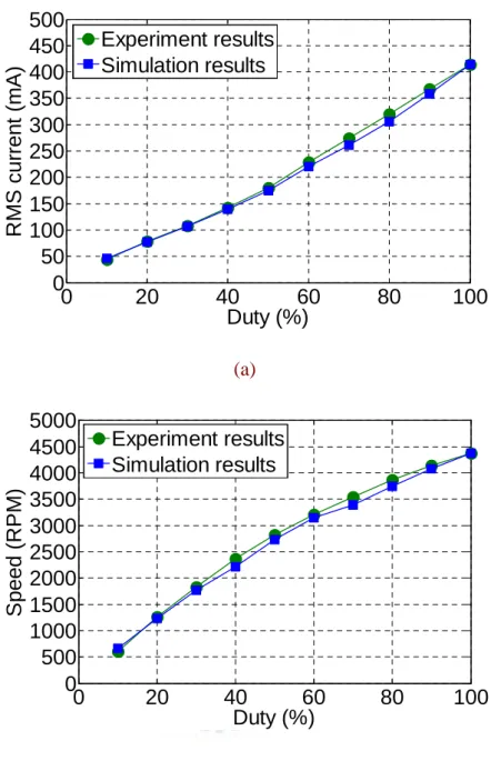
According to previous description, a simple modeling method with an illustrated parameter identification scheme for single-phase BLDC fan motor has been proposed. The parameters of Table I substitute the proposed model and verify with a real single-phase BLDC fan motor by computer simulation and experiment measurement. Using the open-loop voltage-mode of hard-commutation scheme, Fig. 2.14 shows the simulation results of steady-state response under duty ratio 100 %, 80 %, and 50 %, respectively. Fig. 2.15 shows the consistency of the proposed model and the real fan motor, it can be seen that simulation results are close to experiment measurements under different duty ratio. Fig. 2.16 shows the RMS value of phase current and rotor speed curves under different duty ratio, the simulation result is also close to experiment measurement. That is, above of all confirm the validity of the proposed model.
Speed (RPM) Phase current (A) Hall sensor Rotor position (degree) (a)
Speed (RPM) Phase current (A) Hall sensor Rotor position (degree) (b) Speed (RPM) Phase current (A) Hall sensor Rotor position (degree) (c)
Fig. 2.14. Simulation result with open-loop voltage-mode control of hard-commutation scheme under (a) duty = 100 %, (b) duty = 80 %, and (c) duty = 50 %.
0 2 4 6 8 x 10⁻³ -0.8 -0.6 -0.4 -0.2 0 0.2 0.4 0.6 0.8 Time (s) Phas e c u rrent (A) Experiment Result Simulation Result 0 0.002 0.004 0.006 0.008 0.01 -0.8 -0.6 -0.4 -0.2 0 0.2 0.4 0.6 0.8 Time (s) Phas e c u rrnet (A) Experiment Result Simulation Result (a) (b) 0 0.002 0.004 0.006 0.008 0.01 0.012 -0.4 -0.2 0 0.2 0.4 0.6 Time (s) P h ase c u rre nt (A ) Experiment Result Simulation Result 0 0.005 0.01 0.015 0.02 0.025 -0.2 -0.15 -0.1 -0.05 0 0.05 0.1 0.15 0.2 Time (s) P has e c u rrent (A ) Experiment Result Simulation Result (c) (d)
Fig. 2.15. Phase current comparison between simulation result and experiment measurement (a) duty = 100 %, (b) duty = 80 %, (c) duty = 50 %, and (d) duty = 20 %.
0 20 40 60 80 100 0 50 100 150 200 250 300 350 400 450 500 Duty (%) RM S c u rr e n t ( m A) Experiment results Simulation results (a) 0 20 40 60 80 100 0 500 1000 1500 2000 2500 3000 3500 4000 4500 5000 Duty (%) S p eed (R P M ) Experiment results Simulation results (b)
Fig. 2.16. The RMS value of phase current and rotor speed curves under different duty ratios.
Chapter 3
Efficiency Optimization of Single-Phase
BLDC Fan Motor Drives
From previous discussion, it has been found that due to the high operation speed and high winding inductance, the phase current and back-EMF is out of phase if open-loop voltage-mode control of hard-commutation scheme is used. Consequently, a negative torque component is generated and there is the current spike at commutation boundary. Such current spike will bring about acoustic noise, reducing efficiency and increasing power circuit rating. For these reasons, the efficiency optimization control scheme over entire speed control range is presented in this chapter.
3.1
PWM
C
ONTROLS
TRATEGIESThe overall efficiency can be improved from two aspects. One is choosing an appropriate PWM control strategy to reduce the power losses in the inverter. And another is increasing the utilization ratio of phase current as well as motor output power. Based on the motor parameters and application requirements, there are four different switching schemes [21], which encompass most of the currently available techniques, will be introduced for application of single-phase BLDC fan motors. The characteristics and the relative advantages and drawbacks of each scheme are also compared.
3.1.1 PWM Switching Scheme 1
The switch configuration of motor drives is shown in Fig. 3.1. In single-phase BLDC fan motors, the switching state during a PWM period takes only one of the following four possible states: driving, short to high, short to low, and regeneration. In this scheme, positive voltage is applied by permanently turning on S4 while S1 will be pulse-width modulating as shown in Fig. 3.2. When both S1 and S4 are driving states, phase current is increasing. Motor current during the PWM off period passes through an anti-parallel diode of S2 and the conducting transistor S4 (short to low state). In this example, only high side switches are modulated. A similar result will occur when only low side switches are modulated.
S1 S3 S2 S4 VDC Single-Phase BLDC Fan motor Cdc
Fig. 3.1. Switch configuration of motor drives.
(a) (b)
In order to optimize the overall efficiency, the power losses should be accurately calculated and compared the results of different PWM control strategies [23]. Losses are separated into transistor losses and diode losses in the inverter. Loss calculations are function of the circuit waveform. Thus, prior to the development of individual loss expressions, the steady-state waveform under operation condition must be determined. This paper uses the full-bridge inverter with constant switching frequency and constant dc-link input voltage, and the motor control is operated at 3000 RPM based on hard-commutation scheme.
For purpose of calculating the transistor losses, it is convenient to divide into conduction losses and switching losses. Fig. 3.3 shows the model of transistor’s characteristic. During the interval in which the transistor is conducting, the characteristic is approximated with a resistance. For transistor S2 and S4, the conducting current is shown in Fig. 3.4, so the conduction losses over an electrical cycle can be expressed as
∫
⋅ ⋅ = = com T DS S com con S con S dt R t i T P P 0 2 4 , 4 , 2 ) ( 2 1 (3-1)where Tcom is commutation cycle and RDS is conducting resistance of transistor. Due to
2 0 2 4 ( ) 1 rms T S com I dt t i T com = ⋅
∫
(3-2)equation (3-1) can be revised to
2 , 4 , 2 2 1 rms DS con S con S I R P P ⋅ ⋅ = = (3-3)
where Irms is the RMS value of phase current. From (3-3), the conduction loss increases with
− + iDS vDS vDS iDS off on Slope = 1 / RDS (a) (b)
Fig. 3.3. Model of transistor’s characteristic.
t t t i iS2 iS4 Tcom
Fig. 3.4. Conducting current of transistor S2 and S4.
For transistor S1 and S3, the conduction losses over an electrical cycle can be expressed as
∫
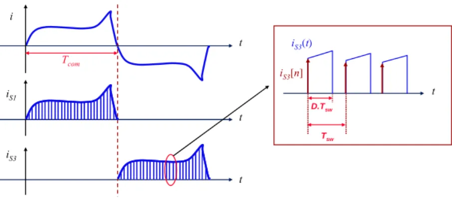
⋅ ⋅ = = com T DS S com con S con S dt R t i T P P 0 2 3 , 3 , 1 ) ( 2 1 . (3-4)However, due to the S1 and S3 is pulse-width modulating, the conducting current is discontinuous as shown in Fig. 3.5. The high winding inductance results in small current ripple, so the conducting current can be approximated as rectangular. This brings about the following result. 2 1 2 3 0 2 3 [ ] 1 ) ( 1 rms k n sw S com T S com I D T D n i T dt t i T com ⋅ ≈ ⋅ ⋅ ≈ ⋅
∑
∫
= (3-5)t t t i iS1 iS3 Tcom t D.Tsw Tsw iS3(t) iS3[n]
Fig. 3.5. Conducting current of transistor S1 and S3.
where D is the duty ratio when motor is operated at 3000 RPM and
sw com
T T
k = (3-6)
where Tsw is the switching period. From (3-6), it means that the conducting current iS3 is
computed at k discrete times, which are separated by a fixed time interval Tsw. Thus, equation
(3-4) can be revised as 2 , 3 , 1 2 1 rms DS con S con S I D R P P ⋅ ⋅ ⋅ ≈ = . (3-7)
From (3-7), the duty ratio and conducting resistance are higher, more conduction losses are generated.
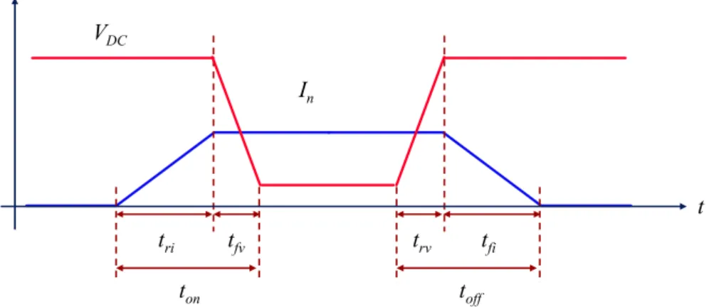
Power dissipation during the turning on and turning off transitions are discussed together. Fig. 3.6 shows the simplified version of the switching waveform. When the transistor is on, the drain-source voltage vDS is approximately zero. At the onset of the turning off, vDS is
assumed to rise linearly until reaching the steady-state off voltage VDC, then the conducting
current decreases to zero. During the turn-on interval, the conducting current increases first, then the drain-source voltage of switch linearly decreases. It is also assumed that the conducting current is constant during switching transition. Therefore, the energy losses during the transistor transition can be formulated as
VDC In tri tfv ton trv tfi toff t
Fig. 3.6. The switching transition during turn-on time and turn-off time.
) ( 2 1 ) ( 2 1 ) ( 2 1 , off on n DC rv fv DC n fi ri n DC sw n t t I V t t V I t t I V E + ⋅ ⋅ ⋅ = + ⋅ ⋅ ⋅ + + ⋅ ⋅ ⋅ = (3-8)
where VDC is the voltage across the transistor when switch is turn-off and In is the conducting
current at nth switching time. tri and tfv are rise time of conducting current and fall time of
voltage drop, respectively. tfi and trv are fall time of conducting current and rise time of
terminal voltage, respectively. ton and toff is the turn-on time and the turn-off time, respectively.
From (3-8), the switching losses of S1 and S3 over an electrical cycle can be expressed as
[
]
( ) 2 1 2 1 ) ( 2 1 2 1 2 1 2 1 1 1 , , 3 , 1 off on k DC com off on n k n DC com k n sw n com sw S sw S t t I I I V T t t I V T E T P P + + ⋅⋅ + + ⋅ ⋅ ⋅ = + ⋅ ⋅ ⋅ = = =∑
∑
= = (3-9) where av n k I I I I1+ 2+⋅ ⋅⋅+ ≈ ⋅ (3-10)where Iav is average current over an commutation cycle, and k is the same with (3-6). Thus,
) ( 2 1 2 1 ) ( 2 1 2 1 , 3 , 1 off on sw av DC off on av DC com sw S sw S t t f I V t t I k V T P P + ⋅ ⋅ ⋅ ⋅ ⋅ = + ⋅ ⋅ ⋅ ⋅ ⋅ ≈ = (3-11)
where fsw is the switching frequency of power inverter. From (3-11), it can be seen that the
switching losses are closely related to the switching frequency and switching transition time. Except the transistor losses, the diode losses also have significant proportion of total power losses. The diode characteristics assumed for this modeling are shown in Fig. 3.7. The diode is modeled as a forward voltage VD during diode conduction. In the off state, the diode
is characterized as an infinite resistance. It is also assumed that the switching time of the diode is much smaller than the switching time of the transistor, so the switching loss of diode is almost zero. Integration of the instantaneous diode power over the electrical cycle provides the conduction losses. The diode conducting current is shown in Fig. 3.8, and it can be seen that the diode conduction time is identical to the transistor off time. Thus, diode conduction losses can be expressed as
− + VD iD vD iD off on (a) (b)
t t t i iD2 iD4 Tcom t (1-D).Tsw Tsw iD4 (t) iD4 [n]
Fig. 3.8. Conducting current of diode D2 and D4.
av D k n sw D D com T D D com con D con D I D V T D n i V T dt t i V T P P com ⋅ − ⋅ ⋅ ≈ ⋅ − ⋅ ⋅ ⋅ ≈ ⋅ ⋅ = =
∑
∫
= ) 1 ( 2 1 ) 1 ( ] [ 2 1 ) ( 2 1 1 4 0 4 , 4 , 2 (3-12)where VD is diode conducting voltage. From (3-12), the diode forward voltage is higher, more
diode conduction losses are generated.
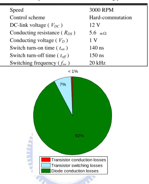
With the above expressions, these losses are combined into the total losses by summing (3-3), (3-7), (3-11), and (3-12) together. The related parameters and the operation conditions list in Table 3.1. So, the total power loss Ptotal in the inverter based on PWM switching
scheme 1 is given as (mW) 79 . 48 ) 1 ( ) ( 2 1 ) 1 ( 2 , 4 , 2 , 3 , 1 , 3 , 1 , 4 , 2 = ⋅ − ⋅ + + ⋅ ⋅ ⋅ ⋅ + ⋅ + ⋅ = + + + + + + + = av D off on sw av DC rms DS con D con D sw S sw S con S con S con S con S total I D V t t f I V I D R P P P P P P P P P . (3-13)
Fig. 3.9 is the pie chart of total power losses for PWM switching scheme 1. There is large proportion of diode conduction losses, and transistor switching losses are secondary. Therefore, the advantages of this scheme are small dc-link capacitance requirement and reduction of transistor switching losses. But, it sacrifices the power losses in diode conduction.
TABLE 3.1
Parameters and operation conditions for calculating power losses
Speed 3000 RPM
Control scheme Hard-commutation
DC-link voltage ( VDC ) 12 V
Conducting resistance ( RDS ) 5.6 mΩ
Conducting voltage ( VD ) 1 V
Switch turn-on time ( ton ) 140 ns
Switch turn-off time ( toff ) 150 ns
Switching frequency ( fsw ) 20 kHz
< 1%
7%
92%
Transistor conduction losses Transistor switching losses Diode conduction losses
Fig. 3.9. Pie chart of total power losses for PWM switching scheme 1.
3.1.2 PWM Switching Scheme 2
In this scheme, positive voltage is applied by pulse-width modulating S1 and S4 simultaneously as shown in Fig. 3.10. When both S1 and S4 are driving states, phase current will increase as in scheme 1. Motor current during the PWM off period decays rapidly through two anti-parallel diodes of S2 and S3, and reverse application of dc-link voltage (regeneration state). That is, two simultaneous switching of two transistors occur in a PWM period.
Similarly, the following will calculate the power losses over an electrical cycle. The parameters and operation condition is identical to PWM switching scheme 1. Due to the
simultaneous switching, the conduction losses of S1 and S4 equal to (3-7) which can be expressed as 2 , 4 , 1 2 1 rms DS con S con S I D R P P ⋅ ⋅ ⋅ ≈ = . (3-14)
The switching losses of S1 and S4 are identical to (3-8), that is
) ( 2 1 2 1 , 4 , 1 off on sw av DC sw S sw S t t f I V P P + ⋅ ⋅ ⋅ ⋅ ⋅ ≈ = . (3-15)
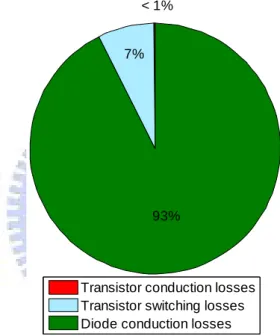
After current commutation, the conduction losses of S2 and S3 are identical to (3-14), and the switching losses are identical to (3-15). On the other hand, the diode conduction losses equal to (3-12) which can be formulated as
av D con D con D con D con D I D V P P P P ⋅ − ⋅ ⋅ ≈ = = = ) 1 ( 2 1 , 4 , 3 , 2 , 1 . (3-16)
Therefore, based on PWM switching scheme 2, the total losses in the power inverter are
(mW) 18 . 97 ) 1 ( 2 ) ( 2 4 4 4 2 , 1 , 1 , 1 = ⋅ − ⋅ ⋅ + + ⋅ ⋅ ⋅ + ⋅ ⋅ ⋅ = ⋅ + ⋅ + ⋅ = av D off on sw av DC rms DS con D sw S con S total I D V t t f I V I D R P P P P . (3-17)
There are twice diode conduction losses and twice transistor switching losses compared to scheme 1. Fig. 3.11 is the pie chart of total power losses for PWM switching scheme 2. In this example, not only the bus capacitance requirement is large, but also the switching losses are increasing. In view of power losses, it is unsuitable for high efficiency motor drives.