行政院國家科學委員會專題研究計畫 期中進度報告
子計畫四:數位電視廣播接收器之數位解調與同步設計及其
平台與晶片製作(1/3)
計畫類別: 整合型計畫 計畫編號: NSC93-2220-E-009-037- 執行期間: 93 年 08 月 01 日至 94 年 07 月 31 日 執行單位: 國立交通大學電子工程學系暨電子研究所 計畫主持人: 周世傑 計畫參與人員: 魏庭楨、嚴紹維、劉瑋昌 報告類型: 完整報告 處理方式: 本計畫可公開查詢中 華 民 國 94 年 5 月 31 日
行政院國家科學委員會補助專題研究計畫
□ 成 果 報 告
■期中進度報告
子計劃四:數位電視廣播接收器之數位解調與同步設計及其平台與晶片製
作
Digital Demodulation and Synchronization Platform Design and Chip
計畫類別:□ 個別型計畫 ■ 整合型計畫
計畫編號:
NSC93-2220-E-009-037
執行期間: 93 年 8 月 1 日至 94 年 7 月 31 日
計畫主持人:
國立交通大學 電子工程學系 周世傑教授
共同主持人:
計畫參與人員:
魏庭楨,劉
瑋昌
,嚴紹維
成果報告類型(依經費核定清單規定繳交):□精簡報告 ■完整報告
本成果報告包括以下應繳交之附件:
□赴國外出差或研習心得報告一份
□赴大陸地區出差或研習心得報告一份
□出席國際學術會議心得報告及發表之論文各一份
□國際合作研究計畫國外研究報告書一份
處理方式:除產學合作研究計畫、提升產業技術及人才培育研究計
畫、列管計畫及下列情形者外,得立即公開查詢
□涉及專利或其他智慧財產權,□一年□二年後可公開查詢
執行單位:國立交通大學
中 華 民 國 94 年 5 月 31 日
摘要
歐規數位電視地面廣播(DVB-T)最近成為國內數位電視廣播標準。因此發展低功率消 耗,價錢低但同時具有彈性及實作性之接收器為目前很重要之研究項目。而具移動性接 收能力之接收器更是一個新的挑戰。 在這個計畫中,我們將設計 DVB-T 之數位後端子系統,這些子系統包含數位降頻器, 通道估計/等化及同步三個部份。此計畫之目標不僅是設計及實作這些子系統,同時和其 他計畫合作將整個解調與解碼系統整合至一個晶片系統。此外,我們將建立 DVB-T 系統 之設計平台,此設計平台不僅是作為 SoC 之相關研究之測試平台,同時它也能幫助我們 發展 DVB 相關系統與 IP 之研究 關鍵字:地面數位電視廣播,正交分頻多工,載波回復,取樣頻率回復,頻域通道估 測。
Abstract
Recently, digital video broadcasting-terrestrial (DVB-T) becomes standard for the digital video broadcasting techniques in Taiwan. Thus, the development of low-power consumption and low cost yet flexible and feasible receiver becomes emergence. Moreover, receiver of DVB-T for portable reception of mobile channel is a new design challenge.
In this project, we will design the digital back-end subsystems of DVB-T. These subsystems include digital frequency down converter, channel estimation/equalization and synchronization. The goals are not only to design and implement these subsystems but also integrate (cooperated with other subprojects) all the demodulation and decoding systems into an System on Chip (SoC). Also, the design platform for DVB-T system will be set up. This platform is to serve as a research and for SoC program at NCU.
Keywords: DVB-T, OFDM, carrier recovery, sampling timing recovery, frequency domain channel estimation
Contents
1. Introduction ...1
2.Receiver Architecture...1
2.1 Symbol Boundary Detection...2
2.2 Carrier Frequency Synchronization ...3
2.3 Sampling Timing Synchronization ...3
2.4 Frequency Domain Channel Estimation ...4
2.5 Simulation Results ...4
3 Memory-less Algorithm for ICFO Estimation ...6
4 Conclusion and Discussion ...10
1. Introduction
In 1997, ESTI (European Telecommunications Standards Institute) release a new standard for digital terrestrial television known as DVB-T [1]. This standard uses the OFDM (Orthogonal Frequency Division Multiplexing) for modulation. OFDM is a kind of multi-carrier modulation that divides the available bandwidth into several orthogonal subcarriers and increases the bandwidth efficiency. Each individual carrier uses conventional modulation such as QPSK (Quaternary Phase Shift Keying) and QAM (Quadrature Amplitude Modulation). DVB-T uses three constellations, QPSK, 16QAM, and 64QAM for different bit rates of targeted video quality. Three transmission modes are specified, they are 2k mode using 1705 subcarriers, 4k mode (3409) and 8k mode (6817). DVB- T insets three kinds pilot: continual pilot, scattered pilots and TPS (Transmission Parameter Signalling) pilots for synchronization, equalization and brings transmission parameters.CFO is divided into integer part and fractional part. The ICFO (Integer CFO) causes the index of sub-carriers shift, and ICI (Inter-Carrier Interference) due to the fractional CFO.
The rest of this report is organized as fallows: The architecture of baseband receiver and simulation results is presented in Section 2. A reduction algorithm and its architecture of jointed estimation of ICFO for DVB-T is posed in Section 3. Finally, the conclusion is drawn in Section 4.
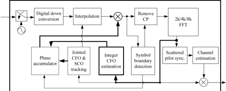
2. Receiver Architecture
Fig. 1 is the block diagram of DVB-T. It contains the digital down converter, the carrier synchronization loop, the sampling synchronization loop, and the frequency domain equalizer. The down converter converts the signal from second IF (4.57 MHz) to baseband. The free running ADC (Analogy to Digital Converter) over samples the second IF output at 36.28 MHz. to relax the specifications of the front end analogy devices. All synchronization loops work in digital domain.
Fig. 1 The receiver architecture of the DVB-T
2.1 Symbol Boundary Detection
The CP (Cyclic Prefix) of DVB-T avoids the ISI from the channel delay dispersal. It is important to find the location of an OFDM symbol in order to maintain the orthogonality. CP is a copy from the tail of an OFDM symbol. By using Maximum Correlation [2] [3],
∑
− + = + ⋅ = 1 0 *() ( ) max arg g N k k k est r i r i N K (1) where r(i) is received signal, N is length of an OFDM symbol , Kest and Ng is length of CP.the peak where means the symbol boundary. A straight forward moving sum architecture in shown in Fig. 2 can be used to reduce the hardware complexity.
2.2 Carrier Frequency Synchronization
The fractional CFO estimation is the phase of the peak value from symbol boundary
detection. After fractional CFO is compensated, the ICI is reduced. Because the ICFO causes the index of subcarrers shift, the location of continual pilot, scattered pilot and TPS are wrong. The ICFO can be estimated by a proposed equation [4].
(
) (
)
⎥ ⎦ ⎤ ⎢ ⎣ ⎡ ⋅ = − + ∈∑
+ * max arg , l 1,k n cpilot k lk n n z z φ (2) where z is FFT output signal, l is symbol index, k is subcarrier index, φ is the estimated CFO and cpilot is the set of continual pilot. φThe RCFO (Remainder CFO) can be estimated jointly with SCO (Sampling Clock Offset). The carrier recovery loop uses a derotator and NCO to compensate CFO. However, the architecture of deortorer need four multipliers and two adders, A CORDIC-based derotator [5], are used to combines the derotator and NCO to reduce hardware complexity.
2.3 Sampling Timing Synchronization
The phase rotation caused by SCO is proportion to the index of sub-carriers. A jointed SCO and CFO estimation algorithm is proposed [2] [3].
⎥ ⎦ ⎤ ⎢ ⎣ ⎡ ∠ = ⎥ ⎦ ⎤ ⎢ ⎣ ⎡ ∠ =
∑
∑
∈ ∈ 2 , 2 1 , 1 C k lk l C k lk l Z φ Z φ ) ( 2 1 ) / 1 ( 2 1 , 2 , 1l l g N N f φ φ π + ⋅ ⋅ − = Δ (3) ) ( 2 / 1 ) / 1 ( 2 1 , 2 , 1l l g N k N t φ φ π + ⋅ ⋅ − = Δwhere fΔ is CFO, tΔ is SCO, Ng is length of CP, N is length of CP. The continual pilots are
divided into two sets; C1 corresponds to pilots on negative sub-carriers and C2 to pilot on
positive sub-carriers.
The sampling timing synchronization has no feed back loop to analogy device, because the free running VCO is used to sample ADC. An interpolator [6] is used to resample the sampled signals. Thus, an interpolator controller decides when to copy or to discard one sample.
2.4 Frequency Domain Channel Estimation
The channel response estimation unit which is aided by scattered pilots estimates both channel response and phase error caused by imperfect synchronization. One dimensional linear interpolation method is used in receiver. It is necessary to detect the scattered pilot mode [7], because scattered pilot is changed in every four OFDM symbols. Assuming the channel response doesn’t have change in four OFDM symbol. In the frequency domain, the channel response of all other sub-carriers is obtained by interpolating stored scattered pilots of the three consecutive OFDM symbol.
2.5 Simulation Results
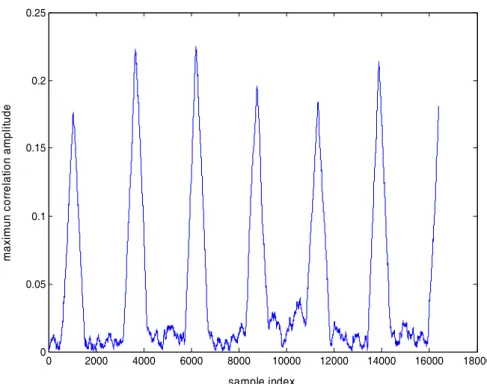
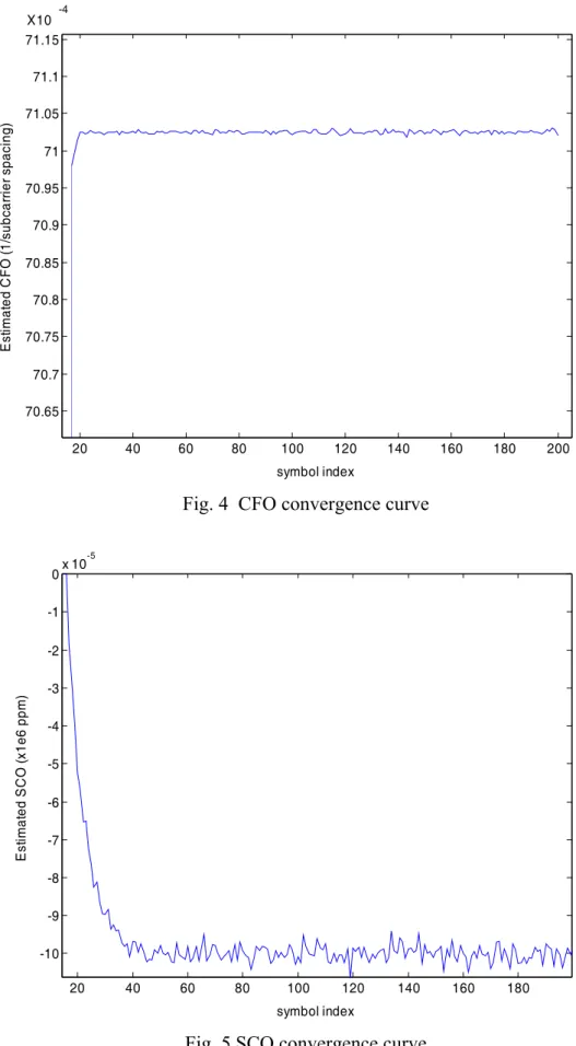
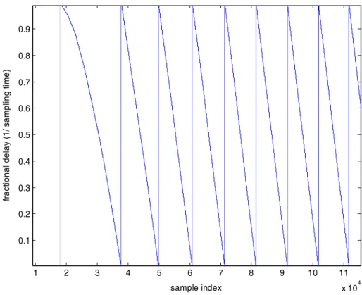
The simulation platform is build by Matlab and C language with infinite word length. The DVB-T baseband receiver can compensate the CFO to 50 subcarrier spacing (about 200kHz at 2k mode) and the SCO to 100ppm. In simulation environment, the fallowing variables are used: CFO = 23.15 subcarrier spacing, SCO = 100 ppm, AWGN = 16.5 db and Rayleigh channel. Fig. 3 is the maximum correlation output, and the peak means the location of OFDM. Fig. 4 and Fig. 5 is the convergence curve of CFO and SCO. The convergence time is about 40 OFDM symbol. Fig. 6 is the interpolation control. The saw means that input signal needs to copy a sample.
0 2000 4000 6000 8000 10000 12000 14000 16000 18000 0 0.05 0.1 0.15 0.2 0.25 sample index m ax imun cor re lat io n a m pl itude
20 40 60 80 100 120 140 160 180 200 70.65 70.7 70.75 70.8 70.85 70.9 70.95 71 71.05 71.1 71.15 symbol index E sti m ate d C F O (1 /s ub ca rr ie r s pa ci ng ) X10 -4
Fig. 4 CFO convergence curve
20 40 60 80 100 120 140 160 180 -10 -9 -8 -7 -6 -5 -4 -3 -2 -1 0x 10 -5 symbol index E st im at ed S C O (x 1e 6 p pm )
1 2 3 4 5 6 7 8 9 10 11 x 104 0.1 0.2 0.3 0.4 0.5 0.6 0.7 0.8 0.9 sample index fra cti on al d el ay (1 / s am pl in g ti m e)
Fig. 6 Interpolation control
3 Memory-less Algorithm for ICFO Estimation
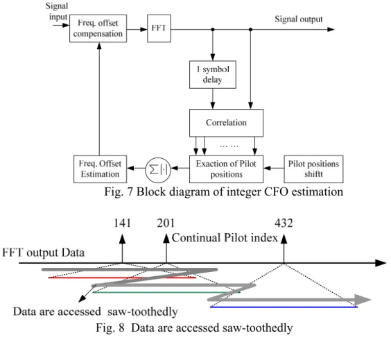
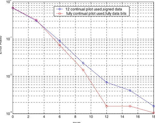
An ICFO estimation algorithms [2] [3] requires a copy of previous symbol shown in Fig. 7. However, the maximum FFT length of DVB-T is 8192. If data word length of FFT output is N bits. It needs to store 8192 × 2 × N bits, which occupy large size. Besides, the correlation operations accesses data of a symbol saw-toothedly shown in Fig. 8. Thus data accessed many times (more than 5 times), and this will increases the power consumption. The sawed–toothed access is caused by the overlapping between estimating ranges of ICFO. By reducing the usage of the continual pilots, the situation of overlapping is avoided. We choose a set that the interval of continual pilot exceeds 100 sub-carriers spacing. The set is {54, 156, 279, 432, 618, 759, 873, 984, 1101, 1206, 1323, 1491}. The number of used continual pilot is 12.
Fig. 7 Block diagram of integer CFO estimation
Fig. 8 Data are accessed saw-toothedly
After solving saw-toothed access, we reduce the usage of storage unit for one symbol delay. Only sign bit of previous OFDM symbol is stored. The advantage of this simplification is not only to decrease the number of storage unit, but also to substitute the multiplication in the correlation with addition and subtraction. The memory-less algorithm is as follows:
(
) (
)
{
54,156,279,432,618,759,873,984,1101,1206,1323,1491}
* max arg , 1, ∈ ⎥ ⎦ ⎤ ⎢ ⎣ ⎡ ⋅ = − + ∈∑
+ cpilot z z sign l k n cpilot k n k l n φ (4)where z is FFT output signal, l is symbol index, k is subcarrier index, φ is the estimated CFO and cpilot is the set of continual pilot. φ
Because only the sign bit of the symbol is stored, it is not necessary to store at every sample that come form FFT output. By using N shift register to store N sign bits of symbol, memory is accessed in every N clock cycles, where N is ward length of memory.
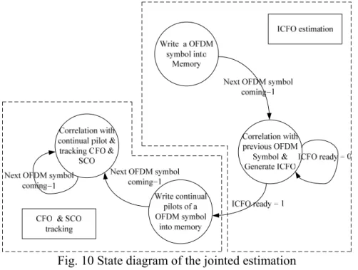
Fig. 9 is performance comparison between the original algorithm and the memory-less one. The test environment is at Rayleigh Channel, CFO = 30.12 subcarrier spacing. The number of test times is 2000. At SNR = 16 dB, the error ratio of the memory-less algorithm is about 8x10⁻²
hardware complexity comparison between the original algorithm and the memory-less one. When memory word length N is 12 bits and the estimation n is 50 subcarrier spacing. The usage of memory reduces 90 %, the access number reduces 94%, and the estimation time reduces 37%. 0 2 4 6 8 10 12 14 16 18 10-3 10-2 10-1 100 E rro r R at io
12 continual pilot used,signed data fully continual pilot used,fully data bits
SNR
Fig. 9 The error ratio of ICFO estimation Table 1 Hardware complexity of ICFO estimation
Conventional New proposed
Storage unit 2048×2×N ⎡2048/N⎤×2×N Access number 2048+2 × n × 45 ⎡2048/N⎤×2 Multiplier 4 0 Adder 4 4 Estimation
Range subcarrier ±n(>50) subcarrier ±50 Estimation
Time 2048 + 2 × n × 45 2048+2048
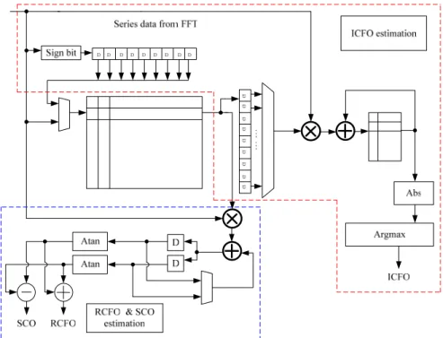
Fig. 10 is the state diagram of jointed ICFO, RCFO and SCO estimation. The first state is to write the sign bit of current OFDM symbol. When next symbol comes from the FFT, it jumps to the second state. In this state, the coming OFDM symbols also are also stored and one correlate with previous stored symbol to generate the integer CFO estimation. In order to
decrease the error ratio of estimation, a voting mechanism is added. This voting mechanism will watch 2~3 OFDM symbol. If 2 among 3 estimations are the same, the value will be considered cowed. With this mechanism, we can reduce the error rate form 10-2 to 10-4~10-6. After estimating the ICFO, a mechanism is used to release hardware resource for RCFO and SCO estimation. In the third state, fully information bits of continual pilots in an OFDM symbol are written into memory. In the fourth state, the continual pilots of two OFDM symbol are correlated and the RCFO and SCO are estimated.
Fig. 10 State diagram of the jointed estimation
The overall architecture for jointed estimation is shown in Fig. 11. ICFO estimation, RCFO and SCO estimation share a memory. The Arctan block and Abs block share the same CORDIC unit for hardware reuse. The operation of this architecture is following the state diagram shown in Fig. 10. In ICFO estimation, the sign bit of samples coming from the FFT output are streamed in the shift registers. After shift registers is full, the temporarily stored data are written into memory. This decease number of access. Another memory is used to store the correlation results. After correlation is complete, the Abs block is used to compute magnitude of the correlation result. The Argmax block finds the index of maximum correlation results which means the ICFO. In RCFO and SCO estimation, the continual pilots are stored into the memory and correlation with the next symbol. The correlation results are divided into two set which describe in Eqn. (3). The summation can compute the CFO, and the subtraction can compute the SCO. The hardware complexity is listed in Table 2.
Fig. 11 Architecture of jointed estimation Table 2 Hardware required for jointed estimation
Memory 171 x 24 (ICFO RCFO & SCO) 101 x 26 (ICFO)
CORDIC 1 (11 iterations )
Multiplier 0 (ICFO)
4 (RCFO & SCO)
Adder 4 (ICFO)
4 (RCFO & SCO)
4 Conclusion and Discussion
In this year, we carry out a simulation platform for DVB-T, which contains digital down converter, carrier recovery loop, sampling timing recovery loop and frequency domain equalizer. At the same time, several simulation results are showed. The convergence time is about 40 OFDM symbol. Besides, a memory-less algorithm reduces the usage of memory reduces 90 %, the access number reduces 94%, and the estimation time reduce 37%., but does not decrease performance a lot. Finally, the architecture of jointed ICFO, RCFO, and SCO is proposed.
5 Reference
[1] ETSI, “Digital Video Broadcasting: Framing Structure, Channel Coding and Modulation for Digital Terrestrial Television, European Telecommunication Standard EN 300 744 V1.5, .November, 2004.
[2] M. Speth, S. Fechtel, G. Fock, H. Meyr, “Optimum receiver design for wireless broad-band systems using OFDM. part I,” IEEE Transactions on Communications, vol. 47, No.11, Nov. 1999, pp. 668 - 1677
[3] M. Speth, S. Fechtel, G. Fock, H. Meyr, “Optimum receiver design for OFDM-Based Broadband Transmission part II: A case study,” IEEE Transactions on Communications, vol. 49, No 4, Apr. 2001, pp. 571 - 578 [4] Dong-Seog Han, Jae-Hyun Seo, Jung-Jin Kim “Fast carrier frequency offset compensation in OFDM
systems,” IEEE Transactions on Consumer Electronics, vol. 47, No. 3, Aug. 2001, pp. 364 - 369
[5] Youngho ahn, Seunghyeon Nahm, Wonyong Sung, “VLSI design of a CORDIC-based derotator,” in Proc. ISCAS '98, pp. 449 - 452
[6] F.M. Gardner, “Interpolation in digital modems. I. Fundamentals,” IEEE Transactions on Communications, vol. 41, No. 2, March 1993, pp. 501 - 507
[7] Ludwig Schwoerer, “Fast pilot synchronization schemes for DVB-H,” proceedings of 4th IASTED, 2004, Banff, Canada. 計畫成果自評: 第一年預定完成之項目 1. 研究數位電視廣播技術之理論及其相關規格。 2. 發展數位電視廣播接收器之數位技術。 3. 研究及發展適合數位電視廣播之下列各子系統之行為及架構。 (1)數位降頻子系統 (2)通道估計/等化子系統 (3)框架/頻率與符號同步子系統 4. 使用硬體描述語言來描述各子系統並做功能模擬。 5. (1),(2)及(3)各子系統整合之硬體架構電腦模擬。 6. 針對DVB-T 系統低電壓低功率之電路設計技術。 進度與成果: 1.已建立系統模擬平台,此平台使用C語言與Matlab,並使用浮點數模擬。 2.模擬DVB-T接收機各子系統功能。 3.完成同步子系統中整數倍頻率誤差估測之硬體設計。 4.未來預計完成其他子系統之硬體設計
可供推廣之研發成果資料表
□ 可申請專利 ;可技術移轉 日期:94 年 5 月 31 日
國科會補助計畫
計畫名稱:子計劃四:數位電視廣播接收器之數位解調與同步設 計及其平台與晶片製作
Digital Demodulation and Synchronization Platform Design and Chip 計畫主持人:周世傑 計畫編號:NSC93-2220-E-009-037 學門領域:微電子學門
技術/創作名稱
DVB-T 同步設計發明人/創作人
周世傑、魏庭楨 中文: 我們設計 DVB-T 之數位後端子系統,這些子系統包含數位降頻 器,通道估計/等化及同步三個部份。此外,我們建立 DVB-T 系 統之設計平台,此設計平台不僅是作為 SoC 之相關研究之測試平 台,同時它也能幫助發展DVB 相關系統技術說明
英文: We design the digital back-end subsystems of DVB-T. Thesesubsystems include digital frequency down converter, channel
estimation/equalization and synchronization. The goals are not only to design and implement these subsystems but also integrate (cooperated with other subprojects) all the demodulation and decoding systems into an System on Chip (SoC).