國 立 交 通 大 學
材 料 科 學 與 工 程 學 系
博 士 論 文
等通道轉角擠型製程對 ZA85 鎂合金之顯微組織
與機械性質改善之研究
A Study on the Microstructures and Mechanical
Properties of the ZA85 Magnesium Alloy
Fabricated by Equal–Channel Angular Extrusion
研 究 生:林哲毅
指導教授:朝春光 博士
.
劉增豐 博士
等通道轉角擠型製程對 ZA85 鎂合金之顯微組織
與機械性質改善之研究
A Study on the Microstructures and Mechanical Properties of the ZA85 Magnesium Alloy Fabricated by Equal–Channel Angular Extrusion
研 究 生:林哲毅 Student:Che–Yi Lin
指導教授:朝春光 博士 Advisor:Dr. Chuen–Guang Chao 指導教授 劉增豐 博士 . Dr. Tzeng–Feng Liu
國 立 交 通 大 學
材 料 科 學 與 工 程 學 系
博 士 論 文
A Dissertation
Submitted to Department of Materials Science and Engineering College of Engineering
National Chiao Tung University in Partial Fulfillment of Requirements
for the Degree of Dotor of Philosophy
in
Materials Science and Engineering June 2014
Hsinchu, Taiwan
i
等通道轉角擠型製程對 ZA85 鎂合金之顯微組織
與機械性質改善之研究
研究生:林哲毅 指導教授:朝春光 博士 研究生:林哲毅 指導教授:劉增豐 博士國 立 交 通 大 學
材 料 科 學 與 工 程 學 系
摘 要
本研究係以重力澆鑄法製成 ZA85 (Mg–8 wt.% Zn–5 wt.% Al) 鎂合金鑄錠, 接著分別將此鑄造材及經過固溶熱處理(solution heat treatment, SHT)的 ZA85 鎂 合金經由等通道轉角擠型(equal–channel angular extrusion, ECAE)以改善合金的 顯微組織與機械性質。研究結果顯示,高溫下對 ZA85 鎂合金進行 ECAE,其晶 粒細化的機制為動態再結晶,ZA85 鎂合金鑄造材的初始晶粒可從 150 μm 大幅 細化至 4 μm。在晶界上的 Mg32(Al,Zn)49 (τ–phase)不連續晶出相尺寸亦從 100 μm 被剪切至 1 μm,且此細小的 τ–phase 顆粒均勻的分布在動態再結晶的晶界上。 在室溫機械性質的部分,試片在經過 ECAE 後,其最大拉伸強度(ultimate tensile strength, UTS)及降伏強度(yield strength, YS)可分別從鑄造材的 175 及 131 MPa 提升至 402 及 281 MPa;在 200 °C 高溫機械性質的部分,經過 ECAE 製程的試 片其 UTS 及 YS 亦分別從鑄造材的 105 及 74 MPa 提升至 249 及 162 MPa。此機 械性質的顯著提升歸因於大幅細化的晶粒以及均勻分布在動態再結晶晶界上的 細小τ–phase 顆粒。ii 出相 τ–phase 皆溶回鎂基地內,晶粒大小相較於鑄造材些微長大至 170 μm。經 過兩階段的 ECAE 製程後,平均晶粒大小可大幅細化至 4 μm,未完全固溶回鎂 基地的τ–phase 被剪切至 1 μm 且均勻的分布在動態再結晶的晶界上,此外,亦 可發現有許多平均尺寸約為 100 nm 的細小析出物 τ–phase 均勻的分布在鎂基地 內,此細小的析出物是在 ECAE 製程中發生動態析出所產生。從拉伸試驗結果 可發現,藉由 SHT + ECAE 製程可進一步提升 ZA85 鎂合金的機械性質。在室溫 以及 200 °C 的環境下,ZA85 鎂合金的 UTS 及 YS 可分別提升至 415 MPa/284 MPa 及 261 MPa/173 MPa。此強化的結果歸因於晶粒細化、析出強化以及細小且均勻 分布的高溫穩定相τ–phase。
經過 ECAE 製程的 ZA85 鎂合金除了可以大幅提升強度外,延性亦能獲得大 幅的改善,在適當的溫度及應變速率範圍內,本研究結果發現經過 ECAE 的 ZA85 鎂合金具由低溫超塑性(low temperature superplasticity, LTSP)以及高應變速率超 塑性(high strain rate superplasticity, HSRSP)。LTSP 的部分,在 300 °C,應變速率 為 1.0 × 10⁻³ s-1以及 1.0 × 10⁻⁴ s-1的測試條件下,ZA85 鎂合金的伸長量分別為 147%及 400%;在 250 °C,應變速率為 1.0 × 10⁻⁴ s-1的測試條件下,伸長量可達 205%。HSRSP 的部分,在 400 °C,應變速率為 1.0 × 10⁻² s-1的測試條件下,伸 長量可達 113%。進一步探討材料的變形機制,ZA85 鎂合金在 300 及 350 °C, 應變速率為 1.0 × 10⁻³ s-1以及 1.0 × 10⁻⁴ s-1的測試條件下,其變形機制為晶界擴 散控制的晶界滑動,在更高溫的 400 °C,其變形機制轉換成差排潛變。 關鍵字:ZA85 鎂合金;等通道轉角擠型;晶粒細化;固溶熱處理;動態析出; 超塑性
iii
A Study on the Microstructures and Mechanical Properties of the
ZA85 Magnesium Alloy Fabricated by Equal–Channel Angular
Extrusion
Student:Che–Yi Lin Advisor:Dr. Chuen–Guang Chao Student:Che–Yi Lin Advisor:Dr. Tzeng–Feng Liu
Department of Materials Science and Engineering
National Chiao Tung University
Abstract
In this study, the as–cast and solution–heat–treated Mg–8 wt.% Zn–5 wt.% Al (ZA85) alloys were subjected to the equal–channel angular extrusion (ECAE). The microstructural evolutions and tensile properties of the experimental alloys were investigated. In the as–cast ZA85 alloy, the initial grain size and precipitate size of 150 and 100 μm were greatly reduced to 4 and 1 μm, respectively, after the ECAE process. The grain–refinement mechanism of the experimental alloy fabricated by the ECAE process is dynamic recrystallization. At room temperature (RT), the ultimate tensile strength (UTS) and yield strength (YS) of the ECAE processed specimens were 402 and 281 MPa, respectively, compared with 175 (UTS) and 131 MPa (YS) for the as–cast specimens. At 200 °C, the UTS and YS of the ECAE processed specimens improved to 249 and 162 MPa, respectively, compared with 105 MPa (UTS) and 74 MPa (YS) for the as–cast specimens. This improvement in tensile properties of the ZA85 alloy was attributed to the refined grains and the well–distributed fine Mg32(Al,Zn)49 (τ–phase) precipitates.
iv
In order to further improve the mechanical properties of the ZA85 alloy, the as–cast ZA85 alloy was subjected to solution heat treatment (SHT). Dynamic precipitation was then induced using two–step ECAE process. After the SHT process, almost all the non–continuous τ–phase dissolved into the α–Mg matrix and the average grain size slightly increased to 170 μm. After six ECAE passes, the average grain size was greatly reduced to 4 μm, and fine τ–phase particles with ~100 nm in size were uniformly distributed in the α–Mg matrix by dynamic precipitation. The combination of SHT + ECAE process was demonstrated to greatly improve the tensile properties of the experimental alloy. By testing over a range of temperatures, the maximum ultimate tensile strength and the yield strength of 415 MPa/284 MPa and 261 MPa/173 MPa were obtained at RT and 200 °C, respectively. The strengthening factors for the SHT + ECAE alloy are the grain refinement, precipitation hardening, and presence of fine and well–distributed τ–phase particles.
It was also demonstrated that ECAE processing produces superplasticity. By testing over a range of temperatures and strain rates, the ECAE processed ZA85 alloy exhibits both low temperature superplasticity (elongations of 147% and 400% at 300 °C with initial strain rates of 1.0 × 10⁻³ s-1 and 1.0 × 10⁻⁴ s-1, respectively; an elongation of 205% at 250 °C with the initial strain rate of 1.0 × 10⁻⁴ s-1) and high strain rate superplasticity (an elongation of 113% at 400 °C with the initial strain rate of 1.0 × 10⁻² s-1). The dominant deformation mechanism for the specimens tested at 300 and 350 °C with the initial strain rates ranging from 1.0 × 10⁻⁴ s-1 to 1.0 × 10⁻³ s-1 is GBS controlled by grain boundary diffusion. At the higher testing temperature of 400 °C, the deformation mechanism for the experimental alloy is dislocation creep.
Keywords: ZA85 alloy; Equal–channel angular extrusion (ECAE); Grain refinement; Solution heat treatment; Dynamic precipitation; Superplasticity
v
致 謝
在這漫長的學習過程中,由衷感謝指導老師朝春光教授以及劉增豐教授這些 年來的諄諄教誨以及悉心指導,在研究遇到困難與瓶頸時,總是能指引我實驗的 方向並給予許多建議,使我獲益良多也讓我能順利地完成研究以及此篇論文。感 謝師範大學工教系的學長郭金國教授提供鎂合金的熔煉場所,才使得本研究得以 順利進行。另外還要特別感謝 UCLA 材料系系主任楊鎮銘教授,在我於美國交 換學生的那一年期間,不論是在研究或是生活上都給予我相當多的幫忙。感謝葉 柏青博士、Tim Tseng、張元瑋、Jonathan Quan 讓我在人生地不熟的異鄉能有回 到家的親切感。 在實驗室的成員中特別要感謝的是蔡浩然學長,從我碩一進實驗室到博士班 畢業這七年,不論是在研究亦或是生活上都給予我許多幫助與建議,本研究使用 的熔煉設備以及 ECAE 設備皆是我們共患難辛苦的成果,在此除了感謝之外也 恭喜學長已順利取得博士學位。感謝王承舜博士、段逸軒博士、林志龍博士、陳 柏至博士、張凱明、黃世陽、王浩仰、陳永昌學長們在課業上及研究上的建議與 協助,也感謝林晟毅、李孝謙、張珮珊、薛舜仁、馬可威、陳俊宏、宋明翰、劉 建寶、王思穎學弟妹們在實驗以及生活上給予的幫忙與照應。另外還要特別感謝 湯季高、羅俊傑、凃宏恩學長們在這漫長的研究路上的陪伴,有你們一起聊天打 嘴砲才能讓苦悶的研究生活更加多采多姿。 要感謝的人實在太多,最要感謝的莫過於是我最親愛的父母、妹妹以及總是 在背後默默支持我的女朋友筱婷,在我遇到挫折瓶頸時給我鼓勵與支持,且提供 我衣食無虞的生活,讓我能心無旁騖、無後顧之憂的完成學業,對於你們的付出, 我的心中充滿萬分的感恩與感動,在此,謹以此論文獻給我摯愛的家人。vi
Contents
Abstract (Chinese)………... i
Abstract (English)……… iii
Acknowledge………... v Contents………... vi Table Captions………. ix Figure Captions……… x
Chapter 1 Introduction
………... 1 1.1 General Background………... 11.2 Organization of the Dissertation………... 3
.References………... 5
Chapter 2 Literature Review
……… 72.1 Development of High–Temperature Magnesium Alloys……… 7
2.2 Equal–Channel Angular Extrusion (ECAE)………... 8
2.3 Deformation Mechanism of Magnesium Alloys………. 12
2.4 Precipitation Hardening of Magnesium Alloys……….. 14
.2.4.1 Precipitation Hardening (T6 Heat Treatment)……….... 14
.2.4.2 Dynamic Precipitation……….... 16
2.5 Superplasticity of Magnesium alloys……….. 17
.References………... 20
Chapter 3 Effects of Equal–Channel Angular Extrusion on
the Microstructure and Tensile Properties of the ZA85
vii
Magnesium Alloy
……….. 40 3.1 Introduction………...3.2 Experimental Procedures……… 3.3 Results and Discussion………... 3.4 Summary and Conclusions………. 3.5 References……….. 40 42 43 49 50
Chapter 4 Effects of Equal–Channel Angular Extrusion on
the Microstructure and Tensile Properties of the
Solution–Heat–Treated ZA85 Magnesium Alloy
………... 72 4.1 Introduction………...4.2 Experimental Procedures……… 4.3 Results and Discussion………... 4.4 Summary and Conclusions………. 3.5 References………... 72 74 75 81 83
Chapter 5 Superplasticity of the ZA85 Magnesium Alloy
Fabricated by Equal–Channel Angular Extrusion
………... 100 5.1 Introduction………...5.2 Experimental Procedures………..………….. 5.3 Results and Discussion………... 5.4 Summary and Conclusions………. 3.5 References………... 100 101 103 108 109
viii
ix
Table Captions
Chapter 3
Table 3.1 Chemical composition of the ZA85 alloy ………... Table 3.2 Composition of matrix and second phase in the ZA85 alloy ……… Table 3.3 Room temperature tensile properties of the ZA85 alloy …………... Table 3.4 High–temperature tensile properties of the ZA85 alloy ……….
70 70 70 71
Chapter 4
Table 4.1 Tensile properties of the ZA–series Mg alloy at room temperature ... Table 4.2 Tensile properties of the ZA–series Mg alloy at high temperature …
99 99
x
Figure Captions
Chapter 2
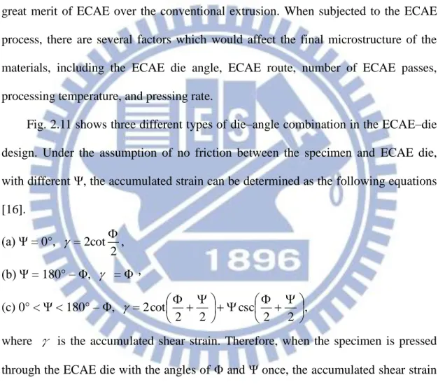
Figure 2.1 Microstructure of the AS21 alloy ………... Figure 2.2 Microstructure of the AE42 alloy ………..………….. Figure 2.3 Creep properties of the AE42, AE41, AS41, and AZ91 alloys …… Figure 2.4 Ternary phase diagram of Mg–Zn–Al alloy ………. Figure 2.5 Creep behaviors between the AZ91 and ZA–series magnesium
alloys ……….………… Figure 2.6 Microstructure of the AJ43 alloy ………..………… Figure 2.7 Creep behaviors of Mg–Al–Sr and Mg–Al–Sr–Ca alloys ………… Figure 2.8 Microstructure of the Mg–Zn–Al–Ca–RE alloy ..……… Figure 2.9 Creep behaviors between As41, AE42, and Mg–Zn–Al–Ca–RE
alloys ………..…………..……….……… Figure 2.10 The cross–sectional figure of the ECAE die……… Figure 2.11 Three types of die–angle combination in the ECAE–die design … Figure 2.12 The relationship between the amount of accumulated strain and
die angles of Φ and Ψ ……… Figure 2.13 Four types of ECAE routes ……… Figure 2.14 Appearance of the 4340 steel subjected to the ECAE process at
350 °C with different pressing rates……… Figure 2.15 Appearance of the AZ31 alloy subjected to the ECAE process
with different temperatures and pressing rates……… Figure 2.16 Microstructure of the as–cast AZ31 alloy after one ECAE pass, (a) dislocation: b[1210], g[1011], and (b) subgrain: b[1210],
25 25 26 27 27 28 28 29 29 30 31 32 32 33 33
xi ] 0 1 10 [ g ………
Figure 2.17 Microstructure of the as–cast AZ31 alloy after four ECAE passes.. Figure 2.18 Microstructures of the compressed Mg–2.0 Zn–0.3 Zr– 0.9 Y alloy at 250 °C with different strain rates (a) 0.001 s-1, (b) 0.01 s-1, (c) 0.1 s-1, and (d) 1 s-1 ……… Figure 2.19 SEM micrograph of the ZA84 alloy subjected to the SHT for (a)
24 h, (b) 48 h, (c) 72 h, and (d) 100 h ……… Figure 2.20 Hardness vs. aging time of the ZA84 alloy after the T6 treatment.. Figure 2.21 (a) A comparison of aging characteristics of the dynamically aged and the as–solutionised samples at 170 °C. (b) Tensile properties of the 6069 and 6061 alloys after dynamic aging and static peak–aging at 170 °C ……… Figure 2.22 Comparison of elongation to failure as a function of deformation
temperature in the (a) ZK60 and (b) AZ91 alloys ……… Figure 2.23 The tensile stress–strain curves of the as–rolled LZ82 alloy …… Figure 2.24 Appearance of the tensile specimens after four ECAE passes at
200 °C and pulling to failure at 200 °C; the upper specimen is untested ………
Chapter 3
Figure 3.1 Optical micrograph of the as–cast ZA85 alloy ……… Figure 3.2 XRD analysis of the as–cast ZA85 alloy ……… Figure 3.3 Optical micrographs of the ZA85 alloy after ECAE at 180 °C for
(a) N = 1, (b) N = 2, (c) N = 4, and (d) N = 6……… Figure 3.4 TEM micrograph of ZA85 alloy after six ECAE passes at 180 °C…
34 34 35 36 36 37 38 38 39 53 53 54 56
xii
Figure 3.5 Area fraction of grains with different sizes after ECAE at (a) 180, (b) 220, and (c) 250 °C ……… Figure 3.6 SEM micrographs of the ZA85 alloy after ECAE at 180 °C for (a)
N = 0, (b) N = 1, (c) N = 4, and (d) N = 6 ……… Figure 3.7 Optical micrographs of the ZA85 alloy after ECAE at 220°C for
(a) N = 1, (b) N = 2, and (c) N = 4 ……… Figure 3.8 Optical micrographs of the ZA85 alloy after ECAE at 250°C for (a) N = 1, (b) N = 2, and (c) N = 4 ……… Figure 3.9 Average grain size with number of passes at different ECAE temperatures ……… Figure 3.10 Hardness at room temperature with different number of passes at
different ECAE temperatures ……… Figure 3.11 Tensile properties at room temperature: (a) UTS, (b) YS, and (c)
elongation ……… Figure 3.12 Tensile properties at 200°C: (a) UTS, (b) YS, and (c) elongation...
Chapter 4
Figure 4.1 Optical micrograph of the as–cast ZA85 alloy ……… Figure 4.2 X–ray diffraction analysis of the as–cast ZA85 alloy ……… Figure 4.3 SEM micrograph of the solution–heat–treated ZA85 alloy ……… Figure 4.4 X–ray diffraction analysis of the solution–heat–treated ZA85 alloy Figure 4.5 SEM micrographs of the solution–heat–treated ZA85 alloy after
the ECAE process for (a) N = 1, (b) N = 2, (c) N = 4, and (d) N = 6 Figure 4.6 Average grain size versus different processing conditions of the
ZA85 alloy ……… 57 59 61 63 65 65 66 68 86 86 87 87 88 90
xiii
Figure 4.7 SEM micrographs of (a) the initial grain boundaries of the
solution–heat–treated alloy after four ECAE passes, (b) the α–Mg matrix of the solution–heat–treated alloy after four ECAE passes, and (c) the α–Mg matrix of the solution–heat–treated alloy after six ECAE passes……… Figure 4.8 X–ray diffraction analysis of the SHT + ECAE ZA85 alloy ……… Figure 4.9 Hardness at room temperature under different processing
conditions of the ZA85 alloy ……… Figure 4.10 Tensile properties of the ZA85 alloy at RT: (a) UTS and (b) YS … Figure 4.11 Tensile properties of the ZA85 alloy at 200°C: (a) UTS and (b)
YS……… Figure 4.12 Elongation of the ZA85 alloy at RT and 200°C ……… Figure 4.13 Tensile fracture surface for (a) the solution–heat–treated sample
tested at RT, (b) the SHT + ECAE sample tested at RT, (c) the solution–heat–treated sample tested at 200 °C, and (d) the SHT + ECAE sample tested at 200 °C ………
Chapter 5
Figure 5.1 Optical micrograph of the as–cast ZA85 alloy ……… Figure 5.2 (a) Optical micrograph and (b) SEM micrograph of the ZA85 alloy
fabricated by ECAE with six passes at 180 °C ……… Figure 5.3 Grain size versus annealing temperature after static annealing of
the material processed by ECAE with six passes at 180 °C ……… Figure 5.4 SEM micrographs of the ECAE processed ZA85 alloy after static
annealing for 1 h at (a) 300, (b) 350, and (c) 400 °C ………
91 93 93 94 95 96 97 112 113 114 115
xiv
Figure 5.5 Stress versus elongation to failure for the ECAE processed ZA85 alloy at the testing temperatures ranging from 250–400 °C with the initial strain rates from 1.0 × 10⁻² to 1.0 × 10⁻⁴ s-1 ……… Figure 5.6 Appearance of the specimens processed by ECAE with six passes
at 180 °C and subsequently tested in tensile to failure under the selected conditions ……… Figure 5.7 Elongation to failure versus initial strain rate over a range of temperatures for the ECAE processed ZA85 alloy……… Figure 5.8 Flow stress versus initial strain rate over a range of temperatures for the ECAE processed ZA85 alloy ……… Figure 5.9 Tensile fracture surface of the ECAE processed specimens tested
with the initial strain rate of 1.0 × 10⁻³ s-1 at (a) 250, (b) 300, (c) 350, and (d) 400 °C, respectively ……… 116 117 118 118 119
1
Chapter 1 Introduction
1.1 General Background
Magnesium–based alloys are among the lightest of all structural metals. They have excellent strength (or stiffness)–to–weight ratio, superior damping capacity, high impact resistance, well electromagnetic shielding characteristics and are cost–effective in engineering applications [1–4]. These properties give magnesium alloys a broad range of applications, especially in electronic industries, aircraft industries as well as automobile industries. In automobile industries, the use of magnesium alloys was only 0.22kg/car in Europe in 1995. However, European Union had demanded that the manufacturers need to take the discarding charges by themselves from 2006 and the recycle rate of discarding cars need to reach to 95% by 2015. The strict laws had greatly increased the consumption of magnesium alloys in automobile industries in Europe. According to the estimation, the growth rate of magnesium usage in Europe is going to reach 30% per year. In addition, the recycle rate of automobile rubbish will arrive at 95% by 2015 in Japan, which also makes Japan automobile manufacturers take more consideration in designing new cars in the future. Thus, the application of magnesium alloys in automobile industries will be increased.
However, the application of magnesium alloys in automobile industries is mainly on the structural components and frame of cars. The engine and transmission system which possess considerable extent in total weight of automobiles are the potential parts for the development of magnesium alloys. The main limitation for the application of magnesium alloys in the engine and transmission system in which the working temperature is about 200 °C is the poor high–temperature properties of the
2
commercial AZ– and AM–series magnesium alloys. These alloys are unsuitable for use at temperature above 120 °C since they show poor creep resistance and large decrease in strength at elevated temperature. This phenomenon is attributed to the presence of the intermetallic phase β–Mg17Al12 which precipitates along grain boundaries and exhibits a low melting point. Thus, grain boundary sliding is allowed to occur even at temperature below 150 °C [5]. In recent year, it has been reported that a ternary addition of a large amount of zinc to binary Mg–Al alloys can completely suppress the formation of the β–phase [6,7]. The precipitate of Mg–Zn–Al (ZA) alloys is Mg32(Al,Zn)49 (τ–phase), which has a higher melting point and decomposition temperature [8]; therefore, ZA alloys exhibit better properties at elevated temperatures compared with commercial AZ alloys.
Besides, there are still some properties which make the applications of magnesium alloys not as extensive as aluminum alloys by now: (I) Poor high–temperature properties because magnesium alloys are all prone to excessive creep deformation when exposed to even low levels of load at high temperature, as mentioned above; (II) Low ductility at room temperature because of their hexagonal close–packed (HCP) crystalline structure which has deficient slip systems; (III) Difficult to smelt and manufacture, and easy to combust with oxygen because of their high chemical activity; (IV) Poor corrosion resistance. In recent years, as the improving surface–treatment techniques, the oxidation resistance of magnesium alloys can be improved effectively. Consequently, improving the poor ductility and high–temperature properties of magnesium alloys in order to broaden their applications is the most important issue of magnesium alloys nowadays.
One of the promising methods adopted to increase both the strength and ductility of materials is microstructural refinement. Such methods are mechanical alloying [9–12], rapid solidification processing [13–15], torsion straining [16–18],
3
reciprocating extrusion [19–21], and equal channel angular extrusion (ECAE) [22–25]. They all resulted in producing bulk ultrafine-grained magnesium alloys with high strength and ductility. Among them, the ECAE process is one of the most often used severe plastic deformation (SPD) methods, which can result in bulk, homogeneous submicron or nanocrystalline microstructure [26–29]. The ECAE die is a block with two intersecting channels of identical cross section. SPD by simple shear occurs in a zone where the two channels meet. Large amount of strain can be accumulated by repeated pressing since the cross section of the specimen is identical after pressing [25]. Also, the ECAE process can be used to eliminate defects such as blow holes and shrinkages introduced by the casting process and to refine coarse precipitates, which will significantly improve the strength and ductility of the materials.
ECAE research on Mg alloys has focused mainly on AZ alloys. The effects of the ECAE process on ZA alloys, which have better high–temperature properties compared with AZ alloys, have not been investigated yet. Therefore, the purpose of this study is an attempt to improve the strength and ductility at room temperature (RT) as well as at elevated temperatures of the ZA85 magnesium alloy by using the ECAE process. The microstructural evolutions after the ECAE process are also investigated.
1.2 Organization of the Dissertation
This dissertation is divided into six chapters.
In chapter 2, the literatures are reviewed, including the development of high–temperature magnesium alloys, characteristics of the ECAE process, deformation mechanism of magnesium alloys, precipitation hardening of magnesium alloys, and Superplasticity of Magnesium alloys.
4
microstructural evolutions after the ECAE process are investigated in details. Both the size of grains and precipitates were greatly refined after the ECAE process. The grain–refinement mechanism of the experimental alloy is characterized as dynamic recrystallization. Moreover, the mechanical properties are also investigated at RT and high temperature of 200 °C. It was found that both the strength and ductility of the experimental alloy increased with increasing number of ECAE passes.
In chapter 4, the as–cast ZA85 alloy was subjected to the solution heat treatment (SHT) prior to the ECAE process in order to further improve the mechanical properties of the experimental materials. The microstructural evolutions after the SHT + ECAE process are also characterized in details. It was found that dynamic precipitation occurred during the ECAE process and formed the fine and well–distributed τ–phase (~100 nm in size) within the α–Mg matrix. RT and high–temperature tensile tests showed that the specimens fabricated by SHT + ECAE have better mechanical properties than those fabricated only by the ECAE process.
In chapter 5, superplasticity of the ZA85 alloy processed by ECAE is investigated. The deformation mechanism of the experimental alloy is characterized in details. It was demonstrated that ECAE processing greatly enhances ductility of the experimental alloy. In this study, the ECAE processed ZA85 alloy exhibits both low temperature superplasticity and high strain rate superplasticity.
Finally, the summary and conclusions of the results in this dissertation is given in chapter 6.
5
References
[1] X.F. Huang, W.Z. Zhang, J.F. Wang, W.W. Wei, Journal of Alloys and Compounds 516 (2012) 186.
[2] K. Cho, T. Sano, K. Doherty, C. Yen, G. Gazonas, P. Moy, B. Davis, R. DeLorme,” Magnesium Technology and Manufacturing for Ultra light Weight Armored
Ground Vehicles”, Proceedings of 26th
Army Science Conference
[3] J. Wang, S. Gao, P. Song, X. Huang, Z. Shi, F. Pan, Journal of Alloys and Compounds 509 (2011) 8567.
[4] M. Bamberger, G. Dehm, Annual Review of Materials Research 38 (2008) 505. [5] Y. Guangyin, S. Yangshan, D. Wenjiang, Materials Science and Engineering A 308
(2001) 38.
[6] A. Srinivasan, U.T.S. Pillai, B.C. Pai, Metallurgical and Materials Transactions 36 A (2005) 2235.
[7] B.H. Kim, S.W. Lee, Y.H. Park, I.M. Park, Journal of Alloys and Compounds 493 (2010) 502.
[8] I.A. Anyanwu, Y. Gokan, S. Nozawa, A. Suzuki, S. Kamado, Y. Kojima, S. Takeda, T. Ishida, Materials Transactions 44 (2003) 562.
[9] C. Suryanarayana, E. Ivanov, V.V. Boldyrev, Materials Science and Engineering A 304–306 (2001) 151.
[10] J.S. Benjamin, T.E. Volin, Metallurgical Transactions, 5 (1974) 1929. [11] J. Patel, K. Morsi, Journal of Alloys and Compounds 540 (2012) 100.
[12] C. Martinez, S. Ordonez, D. Guzman, D. Serafini, I. Iturriza, O. Bustos, Journal of Alloys and Compounds 581 (2013) 241.
[13] E.J. Lavernia, T.S. Srivatsan, Journal of Materials Science 45 (2010) 287. [14] S.S. Nayak, S.K. Pabi, D.H. Kim, B.S. Murty, Intermetallics 18 (2010) 487. [15] Z.Zhang, H. Yu, S. Wang, H. Wang, G. Min, Journal of Materials Science and
6 Technology 26 (2010) 151.
[16] K. Nakamura, K. Neishi, K. Kaneko, M. Nakagaki, Z. Horita, Materials Transactions 45 (2004) 3338.
[17] Z. Horita, T.G. Langdon, Materials Science and Engineering A 410–411 (2005) 422.
[18] A.P. Zhilyaev, T.G. Langdon, Progress in Materials Science 53 (2008) 893. [19] X.F. Guo, D. Shechtman, Journal of Materials Processing Technology 187–188
(2007) 640.
[20] W.P. Yang, X.F. Guo, K.J. Yang, Transactions of Nonferrous Metals Society of China 22 (2012) 255.
[21] S.W. Lee, Y.L. Chen, H.Y. Wang, C.F. Yang, J.W. Yeh, Materials Science and Engineering A 464 (2007) 76.
[22] V.M. Segal, Materials Science and Engineering A 197 (1995) 157. [23] V.M. Segal, Materials Science and Engineering A 386 (2004) 269.
[24] V.M. Segal, K.T. Hartwig, R.E. Goforth, Materials Science and Engineering A 224 (1997) 107.
[25] M. Furekawa, Y. Iwahashi, Z. Horita, M. Nemoto, T.G. Langdon, Materials Science and Engineering A 257 (1998) 328.
[26] W.N. Tang, R.S. Chen, J. Zhou, E.H. Han, Materials Science and Engineering A 499 (2009) 404.
[27] B. Huarte, C.J. Luis, I. Puertas, J. Leon, R. Luri, Journal of Materials Processing Technology 162–163 (2005) 317.
[28] A.L. Etter, T. Baudin, C. Rey, R. Penelle, Materials Characterization 56 (2006) 19.
[29] Y.C. Yuan, A.B. Ma, J.H. Jiang, F.M. Lu, W.W. Jian, D. Song, Y.T. Zhu, Materials Science and Engineering A 588 (2013) 329.
7
Chapter 2 Literature Review
2.1 Development of High–Temperature Magnesium Alloys
In 1960, Volkswagen cooperated with Dow Chemical, Norsk Hydro, and University of Hanover to develop the first high–temperature magnesium alloy: AS41. The main second phase of the AS41 alloy is the thermally stable micro–needlelike Mg2Si phase which precipitates along grain boundaries, resulting good creep resistance at elevated temperature, as shown in Fig. 2.1 [1–3]. The AS21 magnesium alloy which was developed afterwards has better creep resistance than the AS41 alloy. However, the decrease of aluminum content leads to poor casting properties. In 1970, two major types of high–temperature magnesium alloys were developed: AE– and ZA–series alloys. AE–series magnesium alloys which were developed by Dow Chemical and named as AE21 and AE42 had the addition of rare earth elements. The thermally stable intermetallic phase Al11(RE)3 would precipitate along grain boundaries, as shown in Fig. 2.2 [4]. At 150 °C with the load of 50MPa, the creep resistance of the AE42 alloy is a time and five times higher than those of the AS41 and AZ91 alloys, respectively, as shown in Fig. 2.3 [5]. However, the rare earth elements are expensive and easy to vanish during the melting process, which limits widespread applications of such alloys. On the other hand, NL Industries have developed several high–zinc magnesium alloys (ZA), including ZA124, ZA102, AZ88, and AZ55 alloys. The ZA124 alloy showed the same level of creep resistance as the AS41 alloy with better corrosion resistance and fluidity. The corrosion resistance of the ZA102 alloy can be further improved to the level of the AS42 alloy by adding 0.3 wt.% Ca into the alloy [6]. However, it had been reported that the addition of the Ca element would form the eutectic Mg–Al–Zn–Ca phase with low melting temperature.
8
Therefore, the ZA + Ca magnesium alloys cannot be used at temperatures above 175 °C [7]. They also have some problems such as hot cracking and the difficulty to be subjected to the die–casting process. The main precipitates of ZA series magnesium alloys is the τ–Mg32(Al,Zn)49 phase, which has higher melting point and decomposed temperature than those of the β–Mg17Al12 phase [8]. This result is also confirmed by the Mg–Zn–Al phase diagram, as shown in Fig. 2.4. J. Zhang et al. [9] reported that the high–temperature creep resistance of ZA–series magnesium alloys was superior to that of commercial AZ–series magnesium alloys, as shown in Fig. 2.5.
In 1990s, lots of magnesium–alloy suppliers and automobile corporations invested much capital in developing high–temperature magnesium alloys. Hydro corporation added small amount of RE into AS–series alloys in order to remain the creep resistance with the increase of corrosion resistance. In recent year, adding the Ca and Sr elements to replace the high–cost RE elements into magnesium alloys would result in better high–temperature properties [10–12]. The creep resistance of AJ– and AJC–series magnesium alloys is much better than that of the AE42 alloy by forming the high–temperature–stable phase along grain boundaries, as shown in Figs. 2.6 and 2.7. Dead Sea and Honda automobile corporations used the Ca element to replace some amount of RE elements to develop Mg–Zn–Al–Ca–RE alloys. It had been reported that in Mg–Zn–Al–Ca–RE alloys, Al11La3 phase formed in the α–Mg matrix with Al2Ca precipitated along grain boundaries to hinder grain–boundary migration. Therefore, the creep resistance of Mg–Zn–Al–Ca–RE alloys is superior to those of the AE42 and AS41 alloys, as shown in Figs. 2.8 and 2.9 [13].
2.2 Equal–Channel Angular Extrusion (ECAE)
The ECAE process, invented by V.M. Segal in 1995, is one of the most often used SPD methods to result in bulk, homogeneous submicron or nanocrystalline
9
microstructure [14,15]. The ECAE die is a block with two intersecting channels of identical cross section. The inner angle and outer curvature of the ECAE channel are denoted as Φ and Ψ, respectively, as shown in Fig. 2.10. During the ECAE process, the specimen would be pressed through the ECAE channel and be deformed by a pure shear stress. Because the cross–sectional areas of the entrance and outlet channels are identical, large amount of strain can be accumulated by repeated pressing. This is the great merit of ECAE over the conventional extrusion. When subjected to the ECAE process, there are several factors which would affect the final microstructure of the materials, including the ECAE die angle, ECAE route, number of ECAE passes, processing temperature, and pressing rate.
Fig. 2.11 shows three different types of die–angle combination in the ECAE–die design. Under the assumption of no friction between the specimen and ECAE die, with different Ψ, the accumulated strain can be determined as the following equations [16]. (a) Ψ = 0°, 2 2cot , (b) Ψ = 180° – Φ, = Φ, (c) 0° < Ψ < 180° – Φ, 2 2 csc 2 2 cot 2 ,
where γ is the accumulated shear strain. Therefore, when the specimen is pressed through the ECAE die with the angles of Φ and Ψ once, the accumulated shear strain
will be 2 2 csc 2 2 cot 2
. In addition, from the theory of plastic
mechanics, the equivalent strain can be determined by the following e quation: 2 / 1 2 2 2 2 2 2 3 2 2 zx yz xy z y x eq ………(1)
10
where
ε
eq is the equivalent strain,ε
x,ε
y, andε
z are the normal strains in x, y, and zdirections, respectively, and γxy, γyz, and γzx are the shear strains in x–y, y–z, and
z–x planes, respectively. Because the specimen experiences pure shear stress during the ECAE process,
ε
x =ε
y =ε
z =γyz =γzx = 0. Thus, the relationship between theequivalent strain and die angles of Φ and Ψ after one single pass can be evaluated by the following equation:
3 2 2 csc 2 2 cot 2 eq ………(2)
Consequently, after N ECAE passes, the total amount of accumulated strain can be determined by the following equation:
3 2 2 csc 2 2 cot 2 ,total N eq ………(3)
Fig. 2.12 shows the relationship between the amount of equivalent strain and ECAE die angles of Φ and Ψ after one single pass [17]. It can be inferred that the equivalent strain decreases with increasing both Φ and Ψ, while Φ shows more influence than Ψ.
Different routes of ECAE process result in different microstructures. There are four kinds of ECAE routes: route A, route BA, route BC, and route C, as shown in Fig. 2.13 [18]. By using route A in which the sample is deformed in the same surface, the microstructure will become to a thin–foil structure like the one fabricated by the conventional extrusion. Route BA in which the specimen is rotated through 90° in the different direction after each pass. That is, after one pass, if the specimen is subjected to clockwise rotation, the specimen will be rotated counterclockwise after another one pass. Therefore, the shear stress is applied on two specific planes, leading to a non–uniform microstructure. By using route BC in which the specimen is rotated through 90° in the same direction after each pass, the refined and equiaxed–grain
11
structure will be obtained after every 4 ECAE passes [19]. Route C in which the specimen is rotated through 180° after each pass is another way to obtain the equiaxed–grain microstructure.
There are several factors that determine whether the specimen can go through the ECAE die successfully or not, such as the ECAE processing temperature, pressing rate, and initial grain size. As for the ECAE processing temperature, Al alloys which have 12 sets of slip systems because of their face–centered cubic (FCC) crystalline structure can be pressed through the ECAE die successfully even at RT. However, in Mg alloys, there are only three slip systems at RT due to their HCP crystalline structure. Therefore, the ECAE processing temperature is usually higher than 200 °C [20–22]. By applying a back pressure, the ECAE processing temperature can be lowered in the Mg alloys. K. Xia et al. applied a back pressure of 50 MPa to successfully press the AZ31 alloy through the ECAE die for eight passes at 150 °C [23]. In the aspect of the pressing rate, Semiatin et al. subjected the 4340 steel to the ECAE process at 350 °C with different pressing rates and found that high pressing rate would lead to the failure of the sample, as shown in Fig. 2.14 [24]. Kang et al. subjected the AZ31 alloy to the ECAE process with different temperatures and pressing rates and found that the pressing rate could be increased by increasing ECAE processing temperature, as shown in Fig. 2.15 [25]. The initial grain size is also an important factor for the ECAE process. Matsubara et al. subjected the as–cast Mg– 9% Al alloy with the initial grain size of 50 μm to the ECAE process at 200 °C and 8 mm/s and found that the sample experienced failure after only one ECAE pass. Thus, they conducted the conventional extrusion prior to the ECAE process to reduce the grain size of the alloy to about 12 μm. With the same ECAE processing condition, the as–extruded Mg– 9% Al alloy was successfully pressed through the ECAE die for two passes [26]. In summary, raising the ECAE processing temperature can increase the
12
pressing rate; conducting to other processes prior to the ECAE process to preliminarily refine grains can increase the ECAE processing temperature and/or pressing rate.
2.3 Deformation Mechanism of Magnesium Alloys
Magnesium alloys which have HCP crystalline structure have limited slip systems, leading to a poor workability. In order to address this issue, a large number of studies have been carried out to date on single crystals, poly–crystals, and by modeling to understand the deformation and recrystallization mechanisms at a wide range of temperatures [27–31]. Possible slip systems in magnesium alloys include three basal ((0001)<a>), three prismatic (
1010 <a>), and twelve pyramidal (
1011 <a> and
1122 <c + a>). In addition, six
1012 extension twinning systems and a total of twelve
1011 and
1013 contraction twinning [32] systems are also available. The critical resolved shear stress (CRSS) is the minimum stress required to activate the slip systems. It is agreed that, at RT, CRSSbasal < CRSSextension twinning < CRSSprismatic < CRSSpyramidal [29]. The relative ratio of these CRSS values depends on the alloying elements, grain size, strain rate, and temperature. Slip band analysis on Mg single crystals deformed along the hexagonal axis at temperatures ranging from room temperature to 400 °C showed basal and prismatic slip traces at temperatures below 400 °C. After deformation at 400 °C, pyramidal slip traces were observed [33,34]. Galiyev et al. found
11221/31123 slip traces and <c + a> dislocations in a warm deformed (150 °C) ZK60 alloy. They observed increasing <c + a> dislocation density with increasing temperature. The authors ascribed the activation of non–basal slip to locally high compatibility stresses at grain boundaries, which exceeds the CRSS for13 non–basal slip [35].
Understanding the recrystallization mechanisms during hit working of magnesium alloys is also a key to improve workability, to control the grain size and texture and, thus, to alter the final properties. Several recrystallization mechanisms were observed to be operative in magnesium alloys, namely continuous dynamic recrystallization (CDRX) [36,37], discontinuous dynamic recrystallization (DDRX) [38,39], twinning induced dynamic recrystallization (TDRX) [40], and particle stimulated nucleation (PSN) [41]. DRX has been found to be strongly related to the operative slip and twinning systems [35,42–44]. Most studies agree that recrystallization occurs readily when multiple slip operates, i.e., when both basal and non–basal systems contribute to deformation. The main characteristics of CDRX are summarized as follows [45]: (I) Stress–strain curves exhibit a single and smooth maximum, followed by a slow but significant softening stage. A steady state is observed at large strains, which can only be achieved in torsion (at von Mises equivalent ε ~ 30). The flow stress and all the average microstructural parameters remain independent of strain; (II) The crystalline size decreases greatly up to a strain ε ~ 5, then, it increases slowly to reach a steady value at large strains (ε ~ 30); (III) Low–angle boundaries are generated at low strains, and part of them start to transform into high–angle boundaries at moderate strains (ε ~ 1); (IV) A strong crystallographic texture forms at large strains. DDRX typically accompanies regular multipeak stress oscillations on stress–strain curves resulting from constant–strain–rates or constant–displacement–speeds tests [46]. The microstructure after testing shows recrystallized grains containing subgrains. In general, DDRX occurs in low to medium stacking fault energy alloys during the hot deformation. New grains are formed by strain–induced grain boundary motion once a critical shear stain is reached [47]. Dislocation–free grains then grow as deformation continues by bulging into their
14
surroundings and consuming the deformed regions [48].
Janecek et al. proposed that the grain–refinement mechanism for magnesium alloys processed by ECAE is DRX [49]. They have subjected the as–cast AZ31 alloy with the initial grain size of 380 μm to the ECAE process at 200 °C with the pressing rate of 15 mm/min via route BC. After one ECAE pass, the microstructure shows a typical large–deformed structure with high dislocation density in the matrix, as shown in Fig. 2.16. After four ECAE passes, the microstructure of the experimental alloy consists of larger grains of 1–3 μm in size and finer grains of 500–800 μm in size, and no dislocation is observed within some grains, as shown in Fig. 2.17. The dislocation density increases owing to the large amount of strain accumulated by the repetition of ECAE processes. Then, dynamic recrystallization occurs in the area of high dislocation density, producing numerous fine grains and reducing dislocation density. Lv et al. had investigated the DRX evolution of Mg–2.0 Zn–0.3 Zr– 0.9 Y alloy using compression test conducted at 250–400 °C with strain rate rang of 0.001–1 s-1 [50]. They concluded that in the strain rate range of 0.001–0.01 s-1, DRX grains are mainly formed at original grain boundaries and second phase particles, and DRX volume fraction increases with increasing deformation temperature; in the strain rates range of 0.1–1 s-1, DRX grains are mainly formed in twins, and DRX volume fraction decreases with increasing deformation temperature, as shown in Fig. 2.18. The processing map exhibits a deformation domain of complete DRX occurring in the deformation range of 350–400 °C and the strain rate range of 0.001–0.01 s-1.
2.4 Precipitation Hardening of Magnesium Alloys
2.4.1 Precipitation Hardening (T6 Heat Treatment)
In general, T6 heat treatment involves two separate steps, including solution heat treatment (SHT) and artificial aging. SHT in which an alloy or metal is heated to a
15
suitable temperature, is held at that temperature long enough to allow a certain constituent to enter into solid solution, and is then cooled rapidly to form supersaturated solid solution (SSSS). The complete dissolution of phases is depended on the solutionising temperature, time, and chemical composition of the alloy. Among these parameters, the temperature and time are controlled to elucidate the heat treatment process. The artificial aging process results transformation of SSSS into fine precipitates [51]. The artificial–aging behavior is also depended upon the aging time, temperature, and coherency between the matrix and precipitates. Because precipitation is a diffusion–dependant process, higher temperature results in faster nucleation and growth rates. At same aging temperature with longer time, the size of precipitates increases. As a result, the coherency between the matrix and precipitates transforms from coherent to semi–coherent, and then to incoherent. These transformations correspond to the three stages in the age–hardening curve, i.e. under aging, aging, and overaging, respectively. In Mg–Zn–Al alloys, the high Zn content (above 6 wt%) makes it difficult for complete dissolution of the precipitates because Zn exceeds the maximum solid solubility limit [52]. Furthermore, the solutionising time must be carefully determined to allow the maximum dissolution of precipitates into the matrix. Balasubramani et al. [53] have subjected the as–cast ZA84 alloy to the T6 heat treatment at different temperature and/or time in order to determine the optimum parameters for the SHT and artificial aging in the ZA84 alloy. The differential thermal analysis (DTA) showed that the liquidus and solidus temperatures of the ZA84 alloy are 593.44 and 346.62 °C, respectively. Based on the DTA results, the solutionising temperature of the ZA84 alloy is 335 °C which is slightly less than the solidus temperature. They also reported that the amount of dissolved precipitates increases with increasing time at solutionising temperature of 335 °C, whereas phase melting is observed at grain boundaries when solutionising time exceeds 48 h, as
16
shown in Fig. 2.19 [53]. As for the artificial aging, the hardness of the solution–heat–treated ZA84 alloy reached maximum value at 180 °C for 16 h, as shown in Fig. 2.20 [53]. Therefore, the optimum temperature/time required for SHT and artificial aging in the ZA84 alloy are 335 °C/48 h and 180 °C/16 h, respectively.
2.4.2 Dynamic Precipitation
Dynamic precipitation (or dynamic aging) is a process that combines thermo–mechanical processing (TMP) and an aging treatment. After the SHT process, the precipitation reaction occurs simultaneously during TMP. Several studies have reported that materials fabricated by SHT + TMP process have greater mechanical properties than those fabricated by T6 heat treatment [54–57]. Cai et al. have reported that, compared with a static aging process, both the 6061 and 6069 aluminum alloys experienced dynamic precipitaion and that the peak values of the hardness were reached within a shorter time after the SHT + TMP process, as shown in Fig. 2.21 (a) [54]. Moreover, the peak values of hardness, ultimate tensile strength (UTS), and yield strength (YS) of the dynamically aged alloys are also greater than those of the statically aged alloys, as shown in Fig. 2.21 (b) [54]. Roven et al. investigated the precipitation behavior during the ECAE process in an Al–Mg–Si alloy and found that fine–spherical precipitates are dynamically formed during ECAE. The length of the precipitates is much less than that of the precipitates observed after static aging. The hardness values after ECAE at both RT and 175 °C are much higher than the peak values in the specimens statically aged at 175 °C. They suggested that this increase in strength is because the finer precipitates and high dislocation density induced by the ECAE process enhance dislocation strengthening and precipitation refinement strengthening [55]. Hou et al. have subjected the Mg–Gd–Y–Nd–Zr alloy to the hot compression process to investigate the dynamic precipitation behavior [58]. They
17
found that the morphology of precipitates obtained by dynamic precipitation differs from that of the same phase produced by T6 heat treatment. But their orientation relationship with Mg matrix does not change.
2.5 Superplasticity of Magnesium Alloys
Superplastic forming (SPF), defined as elongations of at least 100% and strain rate sensitivity close to 0.5, is an effective method to fabricate hard–to–form materials into complex shapes [59,60]. For SPF to be used in industry, the development of high strain–rate superplasticity (HSRSP), defined as superplasticity occurring at strain rates at or above 1.0 × 10⁻² s-1 [61], is needed, especially for Mg alloys with poor formability. R.B. Figueiredo et al. [62] proposed two strategies for achieving HSRSP in Mg alloys processed by equal–channel angular extrusion (ECAE): (I) by pressing the alloys through a reduced number of passes in order to increase the thermal stability of the microstructure; and (II) by increasing the processing temperature to permit the occurrence of superplastic flow at higher testing temperatures. Another desirable property for developing superplasticity in a material is low temperature superplasticity (LTSP), defined as superplasticity occurring at temperatures at or below 0.55 Tm, where Tm is the alloy melting temperature [61]. The presence of LTSP
is an attractive property in Mg alloys because of their susceptibility to surface oxidation when formed at elevated temperatures and their low formability at temperatures close to RT.
Many previous experiments established that superplasticity requires a small polycrystalline grain size (typically less than 10 μm [63]) and these small grains are generally achieved through the application of SPD. As mentioned in chapter 2.2, ECAE is one of the most popular SPD methods and has proved to be effective in refining grains in various Mg alloys, resulting in improved ductility, strength, and
18
superplasticity [14,26,64–71]. K. Matsubara et al. [26] reported that the Mg–9% Al alloy processed by a combination of extrusion and ECAE exhibited a maximum elongation of 840% at 200 °C with a strain rate of 3.3 × 10⁻⁴ s-1. R.B. Figueiredo et al. [64] reported that an ECAE processed ZK60 alloy showed a maximum elongation of 3050% at 200 °C with a strain rate of 1.0 × 10⁻⁴ s-1. V.N. Chuvil’deev et al. [65] found that the ECAE processed AZ91 alloy possessed 570% in elongation at 300 °C with a strain rate of 3.0 × 10⁻³ s-1 and the ECAE processed ZK60 alloy exhibited 810% in elongation at 260 °C with a strain rate of 3.0 × 10⁻³ s-1, as shown in Fig. 2.22. X. Liu et al. [68] reported that the as–rolled LZ82 alloy exhibited superplasticity with a maximum elongation of 430% at 225 °C and of 120% even at 150 °C with a strain rate of 1.6 × 10⁻⁴ s-1, as shown in Fig. 2.23. Y. Miyahara et al. [69] found that the ECAE processed AZ61 possessed 1320% at 200 °C with a strain rate of 3.3 × 10⁻⁴ s-1, as shown in Fig. 2.24. M. Kawasaki et al. [70] also provided a very detailed tabulation of all papers reporting superplasticity in metals processed by the ECAE process.
Superplastic deformation is an integrated process that combines grain boundary sliding (GBS), dislocation movement, and diffusion in intracrystalline. The m value represents the proportion of GBS, and it is well known that high strain rate sensitivity (typically m close to 0.5) is a characteristic of superplastic metals and alloys [72,73]. The stress exponent (n value), which is reciprocal of the m value, is calculated to determine deformation mechanism of the materials. It has been reported that the n value of the GBS and the dislocation creep mechanisms are 2 and 3, respectively [73,74]. Moreover, GBS is usually accommodated by slip controlled by diffusion [75]. To further understand the deformation mechanism of mateirals, the activation energy for the deformation is calculated under constant strain rate using the following formula [76]:
19 ) / 1 ( ) (ln T nR Q
where Q is the apparent activation energy, n is the stress exponent, R is the gas constant (R = 8.31 J/(K.mol)), σ is the true stress, and T is the absolute temperature. Therefore, according to the relationship of lnσ versus 1/T at different strain rates during the deformation, the activation energy Q can be calculated, and then, the deformation mechanism of materials can be determined.
20
References
[1] P. Zhang, Scripta Materialia 52 (2005) 277.
[2] E. Evangelista, E. Gariboldi, O. Lohne, S. Spigarelli, Materials Science and Engineering A 387–389 (2004) 41.
[3] B. Bronfin, M. Katsir, E. Aghion, Materials Science and Engineering A 302 (2001) 46.
[4] I.P. Mpreno, T.K. Nandy, J.W. Jones, J.E. Allison, T.M. Pollock, Scripta Materialia 48 (2003) 1029.
[5] G. Petterson, H. Westengen, R. Hoier, O. Lohne, Materials Science and Engineering A 207 (1996) 115.
[6] Z. Zhang, R. Tremblay, D. Dube, Materials Science and Engineering A 385 (2004) 286.
[7] A.A. Luo, Materials Science Forum 419–422 (2003) 57. [8] Z. Zhang, A. Couture, A. Luo, Scripta Materialia 39 (1998) 45.
[9] J. Zhang, Z. X. Guo, F. Pan, Z. Li, X. Luo, Materials Science and Engineering A 456 (2007) 43.
[10] B. Jing, S. Yangshan, X. Shan, X. Feng, Z. Tianbai, Materials Science and Engineering A (2006) 181.
[11] K. Hirai, H. somekawa, Y. Takigawa, K. Higashi, Materials Science and Engineering A 403 (2005) 276.
[12] R. Ninomiya, T. Ojiro, K. Kubota, Acta Metallurgica et Materialia (2005) 276. [13] I. Anyanwu, Y. Gokan, A. Suzuki, S. Kamado, Y. Kojima, S. Takeda, T. Ishida,
Materials Science and Engineering A (2004) 93.
[14] V.M. Segal, Materials Science and Engineering A 197 (1995) 157.
[15] V.M. Segal, K.T. Hartwig, R.E. Goforth, Materials Science and Engineering A 224 (1997) 107.
21
[16] Y. Iwahashi, J. Wang, Z. Horita, M. Nemoto, T.G. Langdon, Scripta Materialia 35 (1996) 143.
[17] Y. Iwahashi, Z. Horita, M. Nemoto, T.G. Langdon, Acta Materialia 11 (1997) 4733.
[18] V.M. Segal, Materials Science and Engineering A 386 (2004) 269.
[19] Y. Iwahashi, Z. Horita, M. Nemoto, T.G. Langdon, Acta Materialia 9 (1998) 3317.
[20] K. Mathis, J. Gubicza, N.H. Nam, Journal of Alloys and Compounds 394 (2005) 194.
[21] W.J. Kim, S.I. Hong, Y.S. Kim, S.H. Min, H.T. Jeong, J.D. Lee, Acta Materialia 51 (2003) 3293.
[22] S.R. Agnew, J.A. Horton, T.M. Lillo, D.W. Brown, Scripta Materialia 50 (2004) 377.
[23] K. Xia, J.T. Wang, X. Wu, G. Chen, M. Gurvan, Materials Science and Engineering A 410–411 (2005) 324.
[24] S.L. Semiatin, V.M. Segal, R.E. Goforth, N.D. Frey, D.P. Delo, Metallurgical and Materials Transactions 30A (1999) 1425.
[25] F. Kang, J.T. Wang, Y. Peng, Materials Science and Engineering A 487 (2008) 68. [26] K. Matsubara, Y. Miyahara, Z. Horita, T.G. Langdon, Acta Materialia 51 (2003)
3073.
[27] S. Sandlobes, M. Friak, J. Neugebauer, D. Raabe, Materials Science and Engineering A 576 (2013) 61.
[28] I. Ulacia, N.V. Dudamell, F. Galvez, S. Yi, M.T. Perez–Prado, I. Hurtado, Acta Materialia 58 (2010) 2988.
[29] A. Chapuis, J.H. Driver, Acta Materialia 59 (2011) 1986.
22
[31] S.R. Agnew, O. Duygulu, International Journal of Plasticity 21 (2005) 1161. [32] M. Bamberger, G. Dehm, Annual Review of Materials Research 38 (2008) 505. [33] H. Yoshinaga, R. Horiuchi, Materials Transactions JIM 4 (1963) 1.
[34] H. Yoshinaga, R. Horiuchi, Materials Transactions JIM 5 (1963) 14. [35] A. Galiyev, R. Kaibyshev, G. Gottstein, Acta Materialia 49 (2001) 1199. [36] J.C. Tan, M.J. Tan, Materials Science and Engineering A 339 (2003) 124.
[37] X. Yang, Y. Okabe, H. Miura, T. Sakai, Materials Science and Engineering A 535 (2012) 209.
[38] D.G. Cram, X.Y. Fang, H.S. Zurob, Y.J.M. Brechet, C.R. Hutchinson, Acta Materialia 60 (2012) 6390.
[39] Y. Lin, W. Liu, L. Wang, E.J. Lavernia, Materials Science and Engineering A 573 (2013) 197.
[40] Q. Ma, B. Li, E.B. Marin, S.J. Horstemeyer, Scripta Materialia 65 (2011) 823. [41] L.P. Troeger, E.A. Starke Jr, Materials Science and Engineering A 293 (2000) 19. [42] M.M. Myschlyaev, H.J. McQueen, H. Mwembela, E. Konopleva, Materials
Science and Engineering A 337 (2002) 121.
[43] J.A. del Valle, O.A. Ruano, Materials Science and Engineering A 487 (2008) 473. [44] M.R. Barnett, Journal of Light Metals 1 (2001) 167.
[45] S. Gourdet, F. Montheillet, Acta Materialia 51 (2003) 2685. [46] T. Sakai, J.J. Jones, Acta Metallurgica 32 (1984) 189. [47] F.J. Humphreys, M. Hatherly, Elsevier, Amsterdam (2004).
[48] J.E. Bailey, P.B. Hirsch, Proceedings of the Royal Society A 267 (1962) 11. [49] M. Jenecek, M. Popov, M.G. Krieger, R.J. Hellmig, Y. Estrin, Materials Science
and Engineering A 462 (2007) 116.
[50] B.J. Lv, J. Peng, Y.J. Wang, X.Q. An, L.P. Zhong, A.T. tang, F.S. Pan, Materials and Design 53 (2014) 357.
23
[51] L. Lasa, J.M. Rodriguez–Ibabe, Materials Characterization 48 (2002) 371. [52] ASM, “Metallography, Structure and Phase Diagram”, Metals Handbook 8th
Edition 8 316.
[53] N. Balasubramani, U.T.S. Pillai, B.C. Pai, Journal of Alloys and Compounds 457 (2008) 118.
[54] M. Cai, D.P. Field, G.W. Lorimer, Materials Science and Engineering A 373 (2004) 65.
[55] H.J. Roven, M.P. Liu, J.C. Werenskiold, Materials Science and Engineering A 483–484 (2008) 54.
[56] T. Li, K. Zhang, X.G. Li, Z.W. Du, Y.J. Li, M.L. Ma, G.L. Shi, Journal of Magnesium and Alloys 1 (2013) 47.
[57] M. Vaseghi, A.K. Taheri, S. Hong, H.S. Kim, Materials and Design 31 (2010) 4076.
[58] X.L. Hou, Z.Y. Cao, X. Sun, L.D. Wang, L.M. Wang, Journal of Alloys and Compounds 525 (2012) 103.
[59] R. Kaibyshev, T. Sakai, F. Musin, I. Nikulin, H. Miura, Scripta Materialia 45 (2001) 1373.
[60] T.G. Langdon, Journal of Materials Science 44 (2009) 5998.
[61] Glossary of terms used in metallic superplastic materials, Japanese Industrial Standard, JIS H7007, 1995.
[62] R.B. Figueiredo, T.G. Langdon, Scripta Materialia 61 (2009) 84. [63] T.G. Langdon, Metallurgical Transactions 13A (1982) 689.
[64] R.B. Figueiredo, T.G. Langdon, Advanced Engineering Materials 10 (2008) 37. [65] V.N. Chuvil’deev, T.G. Nieh, M.Yu. Gryaznov, A.N. Sysoev, V.I. Kopylov,
Scripta Materialia 50 (2004) 861.
24 (2009) 222.
[67] B. Chen, D.L. Lin, L. Jin, X.Q. Zeng, C. Lu, Materials Science and Engineering A 483-484 (2008) 113.
[68] X. Liu, R. Wu, Z. Niu, J. Zhang, M. Zhang, Journal of Alloys and Compounds 541 (2012) 372.
[69] Y. Miyahara, Z. Horita, T.G. Langdon, Materials Science and Engineering A 420 (2006) 240.
[70] M. Kawasaki, T.G. Langdon, Journal of Materials Science 42 (2007) 1782. [71] R.B. Figueiredo, T.G. Langdon, Journal of Materials Science 45 (2010) 4827. [72] T.G. Langdon, Journal of Materials Science 44 (2009) 5998.
[73] T.G. Nieh, J. Wadsworth, O.D. Sherby, Superplasticity in Metals and Ceramics, Cambridge University Press, Cambridge (1997).
[74] R.Z. Valiev, Materials Science and Engineering A 59 (1997) 234.
[75] O.D. Sherby, J. Wadsworth, Progress in Materials Science 33 (1989) 169. [76] X. Wu, Y. Liu, Scripta Materialia 46 (2002) 269.
25
Figure 2.1. Microstructure of the AS21 alloy [1].
26
27
Figure 2.4. Ternary phase diagram of Mg–Zn–Al alloy.
28
Figure 2.6. Microstructure of the AJ43 alloy [10].
29
Figure 2.8. Microstructure of the Mg–Zn–Al–Ca–RE alloy [13].
30
31
32
Figure 2.12. The relationship between the amount of accumulated strain and die angles of Φ and Ψ [17].
33
Figure 2.14. Appearance of the 4340 steel subjected to the ECAE process at 350 °C with different pressing rates [24].
Figure 2.15. Appearance of the AZ31 alloy subjected to the ECAE process with different temperatures and pressing rates [25].
34
Figure 2.16. Microstructure of the as–cast AZ31 alloy after one ECAE pass, (a) dislocation: b[1210], g[1011], and (b) subgrain: b[1210],
] 0 1 10 [ g [49].
35
Figure 2.18. Microstructures of the compressed Mg–2.0 Zn–0.3 Zr– 0.9 Y alloy at 250 °C with different strain rates (a) 0.001 s-1, (b) 0.01 s-1, (c) 0.1 s-1, and (d) 1 s-1 [50].
36
Figure 2.19. SEM micrograph of the ZA84 alloy subjected to the SHT for (a) 24 h, (b) 48 h, (c) 72 h, and (d) 100 h [53].
37
Figure 2.21 (a) A comparison of aging characteristics of the dynamically aged and the as–solutionised samples at 170 °C [54].
Figure 2.21 (b) Tensile properties of the 6069 and 6061 alloys after dynamic aging and static peak–aging at 170 °C [54].
38
Figure 2.22. Comparison of elongation to failure as a function of deformation temperature in the (a) ZK60 and (b) AZ91 alloys [65].
39
Figure 2.24. Appearance of the tensile specimens after four ECAE passes at 200 °C and pulling to failure at 200 °C; the upper specimen is untested [69].
40
Chapter 3 Effects of Equal–Channel Angular Extrusion on
the Microstructure and Tensile Properties of the ZA85
Magnesium Alloy
3.1 Introduction
In recent years, the development of magnesium alloys, which generally have excellent properties such as low density, high specific strength, superior damping capacity, high thermal conductivity, and good electromagnetic shielding characteristics, has been attracting much attention [1–4]. These properties make magnesium alloys suitable for a broad range of applications in electronic devices and the aircraft and automobile industries among others. Among various magnesium alloys, Mg–Al–Zn (AZ) alloys are widely used because of their desirable mechanical properties, corrosion resistance, and castability. However, the application of these alloys is limited at temperatures above 120 °C. This is because their heat resistance is inferior to that of aluminum alloys at high temperatures [5]. This phenomenon is attributed to the presence of intermetallic Mg17Al12 (β–phase), which mainly precipitates along grain boundaries and exhibits a low decomposition temperature of approximately 470 °C. Thus, grain boundary sliding occurs even at temperatures below 150 °C [6,7]. It has been reported that the addition of rare earth (RE) elements to magnesium improves its properties at elevated temperatures [8–10]. However, the use of Mg-RE alloys is limited owing to their inferior ductility and the high cost of RE elements. Another way to improve the high–temperature performance of AZ alloys is to suppress the formation of the β–phase [11]. It has been reported that a ternary addition of a large amount of zinc to binary Mg–Al alloys, with a Zn:Al
41
composition of approximately 2:1, can completely suppress the formation of the β–phase [12,13]. The main precipitate of Mg–Zn–Al (ZA) alloys is Mg32(Al,Zn)49 (τ–phase), which has a higher melting point and decomposition temperature than the β–phase [14]; therefore, ZA alloys exhibit better properties at elevated temperatures compared with commercial AZ alloys.
Another disadvantage of commercial magnesium alloys is their poor formability and low ductility at room temperature (RT) as a result of their hexagonal close-packed (HCP) crystal structure, which limits their practical applications. Microstructure refinement is a promising method to increase the ductility and strength of magnesium alloys. Severe plastic deformation (SPD) has been introduced in materials processing to produce ultrafine-grained microstructures [15]. Equal–channel angular extrusion (ECAE) is one of the most popular SPD methods and can produce a homogeneous submicron or nanocrystalline microstructure in bulk materials [16,17]. A block with two intersecting channels that have identical cross sections is used as an ECAE die. Severe deformation occurs via simple shear in the zone where the two channels intersect. Large amounts of strain can accumulate by repeated pressing because the channel cross sections are identical. ECAE is proven to be effective in refining grains in various magnesium alloys, resulting in improved ductility, strength, and superplasticity [18–22].
ECAE research on Mg alloys has focused mainly on AZ alloys. The effects of ECAE on ZA alloys, which have better high-temperature properties compared with AZ alloys, have not been investigated yet. Therefore, we investigate the microstructure and tensile properties of the as–cast ZA85 alloy after ECAE via route BC [23] at 180, 220, and 250 °C.
![Fig. 2.12 shows the relationship between the amount of equivalent strain and ECAE die angles of Φ and Ψ after one single pass [17]](https://thumb-ap.123doks.com/thumbv2/9libinfo/8632900.192545/26.892.133.767.352.913/fig-shows-relationship-equivalent-strain-ecae-angles-single.webp)
![Figure 2.1. Microstructure of the AS21 alloy [1].](https://thumb-ap.123doks.com/thumbv2/9libinfo/8632900.192545/41.892.146.797.161.912/figure-microstructure-as-alloy.webp)
![Figure 2.3. Creep properties of the AE42, AE41, AS41, and AZ91 alloys [5].](https://thumb-ap.123doks.com/thumbv2/9libinfo/8632900.192545/42.892.165.725.328.884/figure-creep-properties-ae-ae-as-az-alloys.webp)
![Figure 2.8. Microstructure of the Mg–Zn–Al–Ca–RE alloy [13].](https://thumb-ap.123doks.com/thumbv2/9libinfo/8632900.192545/45.892.171.701.190.963/figure-microstructure-mg-zn-al-ca-alloy.webp)
![Figure 2.10. The cross–sectional figure of the ECAE die [15].](https://thumb-ap.123doks.com/thumbv2/9libinfo/8632900.192545/46.892.164.702.279.855/figure-cross-sectional-figure-ecae-die.webp)
![Figure 2.11. Three types of die–angle combination in the ECAE–die design [16].](https://thumb-ap.123doks.com/thumbv2/9libinfo/8632900.192545/47.892.161.702.269.882/figure-types-die-angle-combination-ecae-die-design.webp)
![Figure 2.12. The relationship between the amount of accumulated strain and die angles of Φ and Ψ [17]](https://thumb-ap.123doks.com/thumbv2/9libinfo/8632900.192545/48.892.145.771.193.974/figure-relationship-accumulated-strain-die-angles-φ-ψ.webp)
