國 立 交 通 大 學
電子工程學系 電子研究所碩士班
碩 士 論 文
以 Polyimide 高分子材料/NafionTM 質子交換膜
為結構作為 pH-ISFET 之微小化固態電極之研究
The study of Polyimide/NafionTM based structures as a
miniaturized solid-state reference electrode on pH-ISFET
applications
研 究 生: 何彥忠
指導教授: 張國明 教授
桂正楣 教授
以 Polyimide 高分子材料/NafionTM 質子交換膜為結構作為
pH-ISFET 之微小化固態電極之研究
The study of Polyimide/NafionTM based structures as a
miniaturized solid-state reference electrode on pH-ISFET
applications
研 究 生:何彥忠 Student:Yen-Chung Ho
指導教授:張國明 Advisor:Kow-Ming Chang
桂正楣
Cheng-May Kwei
國 立 交 通 大 學
電子工程學系 電子研究所碩士班
碩 士 論 文
A ThesisSubmitted to Department of Electronics Engineering & Institute of Electronics College of Electrical and Computer Engineering
National Chiao Tung University in Partial Fulfillment of the Requirements
for the Degree of Master
In
Electronics Engineering June 2008
Hsinchu, Taiwan, Republic of China
以 Polyimide 高分子材料/NafionTM 質子交換膜為結構作為
pH-ISFET 之微小化固態電極之研究
學生:何彥忠 指導教授:張國明 博士
桂正楣 博士
國立交通大學
電子工程學系 電子研究所碩士班
摘 要
離子感測場效電晶體( Ion-sensitive Field Effect Transistor )是由 Bergveld 在 1970 年首先提出,由於它的尺寸小,反應速度快、可承受外部應力,且與現今 的 CMOS 製程相容,所以在現在的感測元件開發中具有相當大的潛力。 但是由於缺乏一個穩定且微小化的固態參考電極,使得 ISFET 的應用受到 很大的限制。為了要實現一個最簡單且小型結構的 ISFET,在微小化的技術上, 必須要整合一個固態參考電極在單一 ISFET 晶片上,不需要額外再使用到 REFET 或玻璃電極。 從過去的實驗結果可知道,NafionTM混合Polymer的結構具有使REFET的感 測層維持在一個固定的電位且保護它不受離子的干擾的效果。在本篇論文中,我 們成功地以Polyimide/ NafionTM的結構應用到固態參考電極的表面修飾上,使得
固態參考電極因為金屬/溶液接面產生的不穩定電壓被消除。由實驗結果可看 出,令人困擾的電壓不穩問題,大幅地獲得改善。一個單一的ISFET整合固態參 考電極在不需搭配REFET或玻璃參考電極的情況下,對氫離子的靈敏度可達到 56.5 mV/pH而且輸出電壓也展現相當優秀的重線性及線性度,且對鈉離子的靈敏 度只有 7.5 mV/pNa的低靈敏度。以Polyimide/ NafionTM塗佈的固態電極作為參考 電極,在 24 小時下的量測結果顯示,飄移速率更可達到每小時 1.05 mV的低程 度飄移率。
The study of polyimide/NafionTM based structures as a
miniaturized solid-state reference electrode on pH-ISFET
applications
Student: Yen-Chung Ho Advisor: Dr. Kow-Ming Chang
Dr. Cheng-May Kwei
Department of Electronics Engineering & Institute of Electronics
National Chiao Tung University
ABSTRACT
ISFET( Ion-sensitive Field Effect Transistor ) was first developed by Bergveld in 1970s, and because of its small size, fast response, rigidity and compatibility with standard CMOS process, ISFET is an attractive candidate of modern sensor device.
Due to the lack of a stable and miniaturized solid-state reference electrode, the applications of ISFET will be restricted seriously. In order to realize the single ISFET integrated with the simple and compact structure solid-state reference electrode by miniaturized technology, the simple and compact structure of ISFET sensor was fabricated without the additional REFET or glass reference electrode.
From the previous experimental results, we can know the NafionTM mix PR structure can maintain a constant voltage for the sensing layer of REFET and prevent it from the disturbance of ions. In this thesis, we successfully apply the Polyimide/
NafionTM structure to modify the surface of the solid-state reference electrode. The unstable voltage generated from the thermodynamically undefined metal/electrolyte interface can be eliminated. From the experimental results, it is obviously that the troublesome and unstable problem can be greatly improved. Without REFET arrangement in differential measurement or glass reference electrode, the H+ sensitivity of single ZrO2-pH-ISFET integrated with solid-state reference electrode still can reach to 56.5 mV/pH and the output voltage also exhibit high reproducibility and linearity. Furthermore, the Na+ sensitivity can reduce to 7.5 mV/pNa. During a measurement period of 24 hours, the reference electrode with Polyimide/Nafion coating shows a low averaged drift rate of 1.05mV/h.
誌 謝
首先誠摯地感謝指導教授張國明老師與桂正楣老師,兩位老師悉心的教導使 我得以順利完成碩士論文,不時的討論並指點我正確的方向,使我在這些年中獲 益匪淺。老師那豁達開朗的個性,讓我印象深刻,並且也教導了我許多待人處世 的道理,讓我的想法觀念成長許多,老師對學問的嚴謹更是我輩學習的典範。而 擔任桂正楣老師的課程助教,也讓我從中學習到許多寶貴的經驗。 此外,感謝鄧一中老師、鄭兆楨處長在口試中對我論文內容提出的建議及看 法,讓我對研究的題目有更進一步的想法,也讓我見識到了教授思考問題的方 法,確實是值得我們學習。 本論文的完成另外亦得感謝張知天學長、趙高毅學長、林建宏學長及林聖欽 先生的大力協助,不厭其煩的指出我研究中的缺失,且總能在我迷惘時為我解 惑,並在我實驗過程中給於建議及鼓勵,使我對於實驗充滿了信心,而且在平常 的交談中也傳受了我許多人生的經驗談,讓我受益匪淺。另外我要感謝昇宇、詩 帆、菘宏及其他實驗室同學在儀器考核及實驗上的幫助,有了你們讓我可以很快 地進行實驗,順利完成我的碩士論文。因為有你的體諒及幫忙,使得本論文能夠 更完整而嚴謹。 兩年裡的日子,實驗室裡共同的生活點滴,學術上的討論、言不及義的閒扯、 讓人又愛又怕的宵夜、趕作業的革命情感、因為睡太晚而遮遮掩掩閃進實驗 室...,感謝眾位學長姐、同學、學弟妹的共同砥礪,你們的陪伴讓兩年的 研究生活變得絢麗多彩。 最後要感謝我的父母,在我的求學生涯中,你們不曾給予我任何的壓力,讓 我可以自由自在的學習。在我遇到挫折失敗時,你們也都給予我極大的關心與幫 助,讓我覺得相當幸福及幸運。因為有你們的支持與鼓勵,讓我可以無後顧之憂, 順利完成我的學業,取得碩士學位。 誌于 2008.07 何彥忠Contents
Abstract
(in Chinese)
………... iAbstract
(in English)
………... iiiAcknowledgement
………... vContents
………... viTable Captions
………... viiiFigure Captions
………... ixChapter 1
Introduction
1.1 The Importance of pH detection………... 11.2 Techniques for pH detection………. 1
1.3 The pH glass electrodes……… 2
1.4 The ISFET-based pH sensors……… 3
1.5 The importance of reference electrode………. 5
1.6 Solid-state reference electrode integrated with ISFET……. 6
1.7 Motivation of this work and thesis organization…………... 7
1.8 References………. 8
Chapter 2
Theory Description
2.1 Definition of pH……… 102.2 Fundamental principles of ISFET………. 10
2.2.1 From MOSFET to ISFET………. 11
2.2.2 The oxide-electrolyte interface………. 13
2.2.3 Theory for the pH sensitivity of ISFET……… 18
2.3 Non-ideal phenomena of ISFET………... 19
2.3.1 Hysteresis……….. 20
2.3.2 Drift………... 20
2.3.3 Dispersive transport……….. 21
2.3.4 Physical model for drift………... 23
2.4 Summary………... 25
2.5 References………. 26
Chapter 3
Experiment and Measurement
3.1 Introduction………... 293.2 The characteristics of the Polyimide and Nafion………….. 29
3.2.1 Polyimide……….. 29
3.2.2 Nafion………... 30
3.3 Fabrication process flow of ISFET………... 30
3.4 Key steps illustration………. 32
3.4.1 Gate region formation………... 32
3.4.2 Sensing layer deposition………... 32
3.4.3 Polyimide/Nafion membrane-based reference electrodes… 33 3.5 Packing and measurement system……… 34
3.5.1 Current-Voltage (I-V) measurement set-up………. 34
3.5.2 Current-Voltage (I-V) measurement set-up with solid-state reference electrodes……….. 35 3.5.3 Drift measurement set-up with solid-state reference electrodes……….. 35 3.6 References………. 36
Chapter 4
Results and Discussions
4.1 Introduction………... 374.2 Solid-state reference electrode integrated with ISFET……. 37
4.2.1 Solid-state reference electrode………... 37
4.2.2 The glass reference electrode (GRE)……… 39
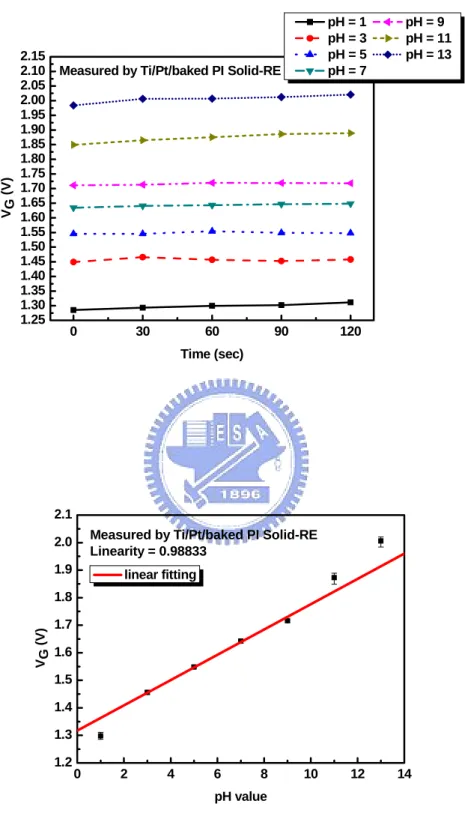
4.3 The experimental results and discussion of solid-state reference electrodes……….. 39 4.3.1 Potential reproducibility and linearity……….. 39
4.3.2 pH sensitivity……… 41
4.3.3 Drift characteristics………... 42
4.4 Conclusions………... 43
4.5 References………. 44
Table Captions
Chapter 1
Table 1-1 Sensitivity for different sensing layers 46
Chapter 3
Table 3-1 ZrO2 Sputtering parameters 53
Table 3-2 Test structures of solid-state reference electrode 54
Chapter 4
Table 4-1 Summary of H+ sensitivity for different test structures 94
Figure Captions
Chapter 1
Fig. 1-1 Conventional pH glass electrode 46
Fig. 1-2 ISFET cross-section structure of ISFET 47
Chapter 2
Fig. 2-1 Schematic representation of a MOSFET (a) and an ISFET (b) cross-section structure
48
Fig. 2-2 ID-VDS curve of an ISFET with Vgs (a), and pH (b) as a parameter 48
Fig. 2-3 Electrode and electrolyte interface 49
Fig. 2-4 Schematic representation of site-binding model 49
Fig. 2-5 Hemholtz model 50
Fig. 2-6 Gouy-Chapman model 50
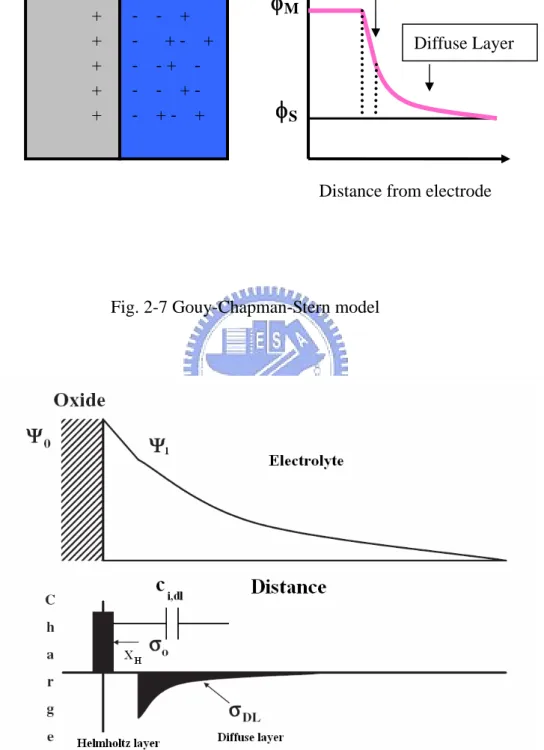
Fig. 2-7 Gouy-Chapman-Stern model 51
Fig. 2-8 Potential profile and charge distribution at an oxide/electrolyte solution interface
51
Fig. 2-9 Schematic representation of carriers hopping through a random array of sites
52
Fig. 2-10 Series combination of the (a) initial (b) hydrated insulator capacitance of sites
Chapter 3
Fig. 3-1 Chemical structure and model of Nafion 55
Fig. 3-2 Fabrication process flow 56
Fig. 3-3 Measurement set-up 59
Fig. 3-4 Detection principle of sensitivity 60
Fig. 3-5 Detection principle of drift 60
Chapter 4
Fig. 4-1 The IDS– VG curves and sensitivity linearity of ZrO2-pH-ISFET measure by glass reference electrode
61
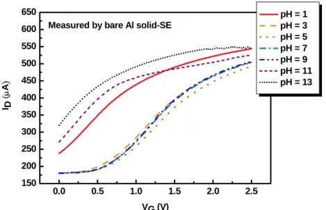
Fig. 4-2 Reproducibility and sensitivity linearity of ZrO2-pH-ISFET measured by bare Al solid-state reference electrode
62
Fig. 4-3 Reproducibility and sensitivity linearity of ZrO2-pH-ISFET measured by Al/NF solid-state reference electrode
63
Fig. 4-4 Reproducibility and sensitivity linearity of ZrO2-pH-ISFET measured by Al/PI solid-state reference electrode
64
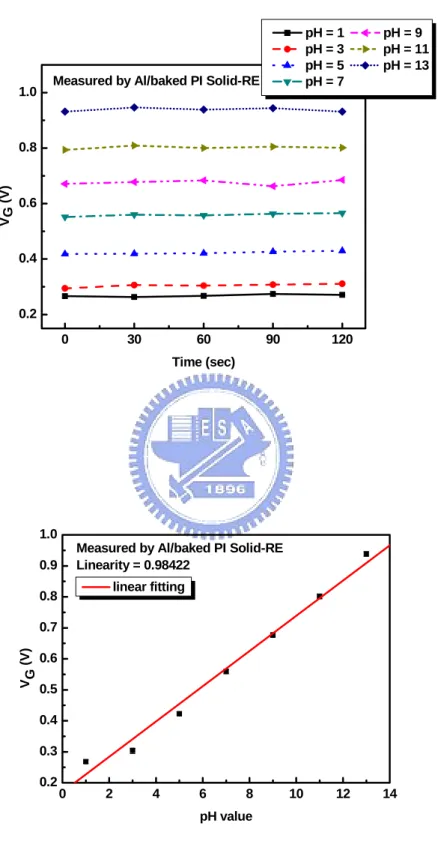
Fig. 4-5 Reproducibility and sensitivity linearity of ZrO2-pH-ISFET measured by Al/PI-mix-NF solid-state reference electrode
65
Fig. 4-6 Reproducibility and sensitivity linearity of ZrO2-pH-ISFET measured by Al/PI/NF solid-state reference electrode
66
Fig. 4-7 Reproducibility and sensitivity linearity of ZrO2-pH-ISFET measured by Al/baked PI solid-state reference electrode
67
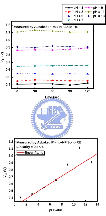
Fig. 4-8 Reproducibility and sensitivity linearity of ZrO2-pH-ISFET measured by Al/baked PI-mix-NF solid-state reference electrode
68
Fig. 4-9 Reproducibility and sensitivity linearity of ZrO2-pH-ISFET measured by Al/baked PI/NF solid-state reference electrode
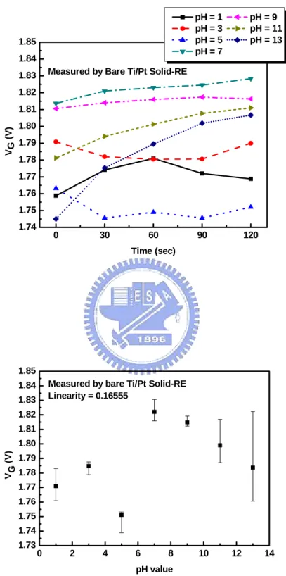
Fig. 4-10 Reproducibility and sensitivity linearity of ZrO2-pH-ISFET measured by bare Ti/Pt solid-state reference electrode
70
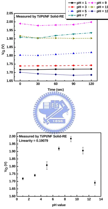
Fig. 4-11 Reproducibility and sensitivity linearity of ZrO2-pH-ISFET measured by Ti/Pt/NF solid-state reference electrode
71
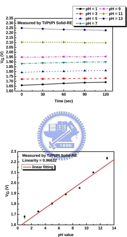
Fig. 4-12 Reproducibility and sensitivity linearity of ZrO2-pH-ISFET measured by Ti/Pt/PI solid-state reference electrode
72
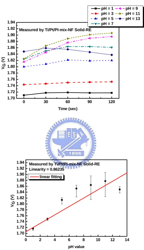
Fig. 4-13 Reproducibility and sensitivity linearity of ZrO2-pH-ISFET measured by Ti/Pt/PI-mix-NF solid-state reference electrode
73
Fig. 4-14 Reproducibility and sensitivity linearity of ZrO2-pH-ISFET measured by Ti/Pt/PI/NF solid-state reference electrode
74
Fig. 4-15 Reproducibility and sensitivity linearity of ZrO2-pH-ISFET measured by Ti/Pt/baked PI solid-state reference electrode
75
Fig. 4-16 Reproducibility and sensitivity linearity of ZrO2-pH-ISFET measured by Ti/Pt/baked PI-mix-NF solid-state reference electrode
76
Fig. 4-17 Reproducibility and sensitivity linearity of ZrO2-pH-ISFET measured by Ti/Pt/baked PI/NF solid-state reference electrode
77
Fig. 4-18 Sensitivity of ZrO2-pH-ISFET measured by bare Al solid-state reference electrode
78
Fig. 4-19 Sensitivity of ZrO2-pH-ISFET measured by Al/NF solid-state reference electrode
78
Fig. 4-20 Sensitivity of ZrO2-pH-ISFET measured by Al/PI solid-stat reference electrode
79
Fig. 4-21 Sensitivity of ZrO2-pH-ISFET measured by Al/PI-mix-NF solid-state reference electrode
79
Fig. 4-22 Sensitivity of ZrO2-pH-ISFET measured by Al/PI/NF solid-state reference electrode
80
Fig. 4-23 Sensitivity of ZrO2-pH-ISFET measured by Al/baked PI solid-state reference electrode
80
Fig. 4-24 Sensitivity of ZrO2-pH-ISFET measured by Al/baked PI-mix-NF solid-state reference electrode
81
Fig. 4-25 Sensitivity of ZrO2-pH-ISFET measured by Al/baked PI/NF solid-state reference electrode
Fig. 4-26 Sensitivity of ZrO2-pH-ISFET measured by bare Ti/Pt solid-state reference electrode
82
Fig. 4-27 Sensitivity of ZrO2-pH-ISFET measured by Ti/Pt/NF solid-state reference electrode
82
Fig. 4-28 Sensitivity of ZrO2-pH-ISFET measured by Ti/Pt/PI solid-state reference electrode
83
Fig. 4-29 Sensitivity of ZrO2-pH-ISFET measured by Ti/Pt/PI-mix-NF solid-state reference electrode
83
Fig. 4-30 Sensitivity of ZrO2-pH-ISFET measured by Ti/Pt/PI/NF solid-state reference electrode
84
Fig. 4-31 Sensitivity of ZrO2-pH-ISFET measured by Ti/Pt/baked PI solid-state reference electrode
84
Fig. 4-32 Sensitivity of ZrO2-pH-ISFET measured by Ti/Pt/baked PI-mix-NF solid-state reference electrode
85
Fig. 4-33 Sensitivity of ZrO2-pH-ISFET measured by Ti/Pt/baked PI/NF solid-state reference electrode
85
Fig. 4-34 Na+ sensitivity and sensitivity linearity of ZrO2-ISFET by Ti/Pt/PI/NF solid-state reference electrode
86
Fig. 4-35 Na+ sensitivity and sensitivity linearity of ZrO2-ISFET by Ti/Pt/baked PI/NF solid-state reference electrode
87
Fig. 4-36 Summary of H+-sensitivity for different test structures 88
Fig. 4-37 Summary of H+-linearity for different test structures 88
Fig. 4-38 Drift of ZrO2-pH-ISFET measured by glass reference electrode for 7 hours
89
Fig. 4-39 Drift of ZrO2-pH-ISFET measured by Ti/Pt/PI solid-state reference electrode for 7 hours
89
Fig. 4-40 Drift of ZrO2-pH-ISFET measured by Ti/Pt/PI-mix-NF solid-state reference electrode for 7 hours
90
Fig. 4-41 Drift of ZrO2-pH-ISFET measured by Ti/Pt/PI/NF solid-state reference electrode for 7 hours
Fig. 4-42 Drift of ZrO2-pH-ISFET measured by Ti/Pt/baked PI solid-state reference electrode for 7 hours
91
Fig. 4-43 Drift of ZrO2-pH-ISFET measured by Ti/Pt/baked PI-mix-NF solid-state reference electrode for 7 hours
91
Fig. 4-44 Drift of ZrO2-pH-ISFET measured by Ti/Pt/baked PI/NF solid-state reference electrode for 7 hours
92
Fig. 4-45 Summary of drift for different test structures 92
Fig. 4-46 Drift of ZrO2-pH-ISFET measured by Ti/Pt/PI/NF solid-state reference electrode for 24 hours
93
Fig. 4-47 Drift of ZrO2-pH-ISFET measured by Ti/Pt/baked PI/NF solid-state reference electrode for 24 hours
Chapter 1
Introduction
1.1 The importance of pH detection
pH is one of the most common measurement parameters because so many biological and chemical processes are dependent on pH. We can find the chemical characteristics of a substance by measuring pH. For example, the body fluid of living organisms usually has specific pH range. If the pH of the human blood changes by a little as 0.03 pH units or less the functioning of the body will be greatly impaired [1]. In our surroundings, the pH values of rivers, waters and soils affect the livability of fishes, animals and plants. In a word, a little change of the pH value will result in serious impact to these organisms. Hence, it is necessary to measure pH value accurately. Commonly used methods for pH detection will be introduced in the next section.
1.2 Techniques for pH detection
Traditionally, there are many methods for detecting pH value, such as (1) indicator reagents (2) pH test strips (3) metal electrode (4) glass electrode. The methods (1) and (2) are differentiated from colors and are impossible to reach high accuracy. The method (3) is difficult for daily use and reproducing. Because of some limitations in practical applications of the first three methods, the method (4) glass electrode becomes the most widely used method for pH measurement, and is considered to be the standard measuring method. Therefore we will have an introduction for glass electrode.
1.3 The pH glass electrodes
In 1906, the first pH glass electrode was developed by M. Cremer with Fritz Haber and many efforts have been devoted to improve its application. The pH glass electrode consists of an electrode membrane that responds to pH, which only permits the passage of hydrogen ions in solution. Generally, a fixed concentration of HCl or a buffered chloride solution inside in contact with an internal reference electrode, which use of Ag/AgCl, as shown in Fig. 1-1.
When the glass electrode is immersed in the solution, the outer bulb surface will be hydrated (the thickness is about 0.3-0.6 nm) and exchange sodium ions for hydrogen ions to build up a surface layer of hydrogen ions [2]. The build up of charges on the inside of the membrane is proportional to the amount of hydrogen ions in the outside solution. The potential difference between inside and outside the thin glass membrane is proportional to this difference in pH value in the external solution, and we can derive the potential difference from Nernst equation:
0 ln H
RT E E
nF α +
= + (1-1)
where E = electrode potential, E0 = standard potential of the electrode, R = gas constant (8.31441JK-1mol-1), T = temperature (in Kelvin), n = valence (n = 1 for hydrogen ions), F = Faraday constant and αH+ = activity of hydrogen ions.
According to this equation, providing that at one side of the interface the activity of the ion of interest is kept constant, the electrode potential is direct logarithmic function of the ion activity on the other side. Because of its ideal Nernstian response independent of redox interferences, short balancing time of electric potential, high selectivity, reliability and wide pH range, glass electrode is most widely used for pH measurement. However, glass electrode has several drawbacks for many industrial applications. Firstly, they are unstable in alkaline or HF solutions or at temperatures higher than 100°C. Also, they exhibit a sluggish response and are difficult to
miniaturize. Moreover, they cannot be used in food or in vivo applications due to their fragility of the glass. Finally, due to the need for internal liquid reference solutions, the traditional glass electrode must be used at the vertical position for chemical reproducibility. Consequently, it is very inconvenient in applications. In order to overcome these drawbacks, the all-solid-state electrode sensors have been investigated for a long time. However, it is obvious that the unavailability of a reliable miniature reference electrode hinders many applications. There is an increasing need for alternative pH sensors.
According to ref [1], there are many new techniques for pH detection: (1) Optical-fiber-based pH sensors (2) Mass-sensitive pH sensors (3) Metal oxide pH sensors (4) Conducting polymer pH sensors (5) Nano-constructed cantilever-based pH sensors
(6) ISFET-based pH sensors (7) pH-image sensors
As mentioned above, the ISFET-based pH sensor is a new technique for pH detection. Due to the highly advanced IC fabrication techniques, a miniature ISFET-based pH sensor is of particular interest in the field of medical diagnostics for use in implantable devices or on catheter tips and shows a great potential for application in chemical and biological sensing devices.
1.4 The ISFET-based pH sensors
The ion sensitive field effect transistor (ISFET) was invented by P. Bergveld in 1970 [3] and has been introduced as the first miniaturized silicon-based chemical sensor. The ISFET structure is similar to the Metal Oxide Semiconductor Field Effect Transistor (MOSFET) except that metal gate. In other words, ISFET is a special type of MOSFET without a metal gate, in which the gate oxide is directly exposed to the buffer solution. When the sensing layer of the ISFET contacts with the electrolyte, it will induce a surface potential between the gate oxide and electrolyte. For the
different pH value buffer solution, there are different surface potentials induced at the surface. Hence the electric field at the interface will be changed and the channel conductance that affects the drain current will also be modulated. Since the channel conductance and drain current can be modulated. For instance, the general expression for the drain current of the ISFET in the linear region is
(
)
1 2 OX D GS T DS DS C W I V V V V L μ ⎡ ⎤ = ⎢ − − ⎥ ⎣ ⎦ (1-2)Therefore, in order to be able to measure the threshold voltage of the ISFET, it is necessary to bias it at constant drain current (ID) and constant drain to source voltage
(VDS). In such situation there will be only two variables, VG and VT. When VT varies,
the gate voltage must adjust by an equal amount to compensate. The circuit to maintain constant ID and constant VDS can be carrying out by using feedback OP
amplifiers and current sources and sinks [4]. Different pH concentrations will induce different voltage variation, so we can determine the pH value of the test solution from the potential difference. The more detailed operation mechanisms and theories are presented in Chapter 2. By these method, we can plot a standard linear line between gate voltages and various pH values, and this standard can be taken to measure an unknown acid or alkaline solution [5].
The development of ISFET has been on going for more than 35 years, and the first ISFET sensing layer exploited was silicon dioxide (SiO2), which showed an unstable sensitivity and a large drift. Recently, there are many materials have been investigated and applied for the ion sensing layer. For example, high dielectric constant insulator materials were used as pH-sensing layers because of their high sensitivity performance and long-term reproducibility. Table 1-1 shows the sensitivities and test ranges of different sensing layers. It is found that pH sensitivity is one of the important characteristic parameters of the ISFET devices and the response of the ISFET is mainly determined with the type of the sensing layer, therefore the sensing material plays a significant role. In the study, we use zirconium
oxide (ZrO2) as the ion sensing layer. However, because of the poor interface between the high sensing layer and silicon substrate, all sensing layers must be deposited on the thermally grown SiO
k
2 to improve the interface properties [6], which are low density of interface state, small stress, and good adhesion. Hence, with the study of sensing layer, some material is found can detect different ions, for example, K+, Na+, Ca+, and H+ ions.
Compare with the conventional pH-meter using glass electrode, ISFET has following features:
(1) Small size and weight (2) Short response time
(3) Potential of mass production at low cost (4) Compatible with the standard CMOS process (5) Small sample requirement
However, for most of the sensor devices, it is possible to fabricate a variety of chemical sensors with a small size down to the micrometer scale so that only a small amount of the test solution should be necessary, but this improvement is useless because of the lack of a miniaturized reference electrode [7]. Hence, how to reduce the scale of macroscopic commercial reference electrode is a major challenge. In this study, the problems of the miniaturized solid-state reference electrodes are investigated for practical applications of pH-ISFET. We will discuss the importance of reference electrode in the next section.
1.5 The importance of reference electrode
The reference electrode is an important part of electrochemical measurement. The quality of the reference electrode is especially important in the direct potentiometric measurement of pH and blood electrolytes. For a material to be a good reference electrode, the desired parameters are high sensitivity, good linearity, fast response
time, long life, chemical and thermal independence.
An ideal reference electrode for use as the ISFET gate terminal should provide [4]:
(1) An electrical contact to the solution from which to define the solution potential;
(2) An electrode/solution potential difference (Eref) that does not vary with
solution composition.
In other words, it is expected that it is sufficiently stable, that it is not fouled by a sample, and that the reference electrode itself does not contaminate a sample. It is advisable that a reference electrode is easy to manufacture and use, that it is service-free and cheap, and has a long life-time. The conventional silver chloride or calomel electrodes provide both of these functions by maintaining an electrochemical equilibrium with the solution. Such an electrode requires compartments filled with a reference solution and separated by a permeable membrane.
1.6 Solid-state reference electrode integrated with ISFET
Due to the lack of metal gate electrode for ISFET, the input gate voltage will be applied through a reference electrode, which provides a stable potential in the electrochemical measuring system, as shown in Fig. 1-2. The most simple and compact structure of ISFET is the all-solid-state reference electrode integrated with ISFET in a single chip. However, very few papers have been devoted to the miniaturization of the reference electrode, although hundreds of papers have been published concerning various sensing devices such as ISFET [8]. For some analytical applications, it is desirable to use all-solid-state pH sensor when the electrode has to work in a non-vertical position. All-solid-state electrodes have several advantages over glass electrode with internal filling solution, one of them being the minimization of the contribution from the liquid junction. Furthermore, all-solid-state electrodes
may be exposed to higher temperatures and pressures than the liquid filling electrodes, and they need not be used in an upright position. They are miniaturizable, do not need refilling with internal solution and can be prepared in various shapes and sizes [9].
Today, due to the frequent applications of potentiometry with ion-selective electrodes in clinical and biological measurements, it is important that a reference electrode is necessary to miniaturize. Hence there has been a considerable effort to develop solid state reference electrodes over the past years. However, it is still a problem to create a long-term stable solid-state reference electrode. Because potential at the solid/liquid interface is thermodynamically undefined, it will lead to significant errors in pH measurement. The unstable problem may come from the redox reaction or other chemical reactions at the metal reference electrode and the liquid interface, i.e. the solid/liquid interface. Hence, providing a stable potential at the interface is a major challenge for miniaturized solid-state reference electrode integrated with ISFET.
1.7 Motivation of this work and thesis organization
The presence of the commercial macro reference electrode is unwelcome in clinical and biological measurements. For miniaturization, many groups have been devoted to the development of miniature solid-state reference electrodes. However, these attempts do not seem to be successful with regard to the reproducibility and reliability in comparison with tradition reference electrodes having an internal solution, such as Ag/AgCl/aq.KCl and Hg/Hg2Cl2/aq.KCl.
In this study, we will focus on investigating the miniaturization of solid-state reference electrodes with no internal aqueous phase. By directly coating polyimide/NafionTM membrane-based materials on the metal reference electrodes, new reference electrodes with no internal aqueous phase have been carried out. The protective membranes were deposited by using a drop-coating method.
The entire fabrication process and measurement details will be described in chapter 3. After measuring the characteristics of the devices, we bring up some ideas about the experimental results and show the conclusions in chapter 4. At last, some works are presented to investigate in the future.
1.8 References
[1] Y. Q. Miao, J. R. Chen and K. M. Fang, “New technology for the detection of pH”, J. Biochem. Biophys. Methods, vol. 63, pp. 1-9, 2005.
[2] P. Bergveld, “ISFET, Theory and Practice”, in IEEE Sensor Conference, Toronto, Oct. 2003.
[3] P. Bergveld, “Development of an ion sensitive solid-state device for neurophysiological measurements”, IEEE Trans.Biomed. Eng.,vol. BME-17, p.70, 1970.
[4] Paul A. Hammond, Danish Ali, and David R. S. Cumming, ”Design of a Single-Chip pH Sensor Using a Conventional 0.6-um CMOS Process.”, IEEE Sensors Journal, vol. 4, no. 6, Dec, 2004.
[5] Kow-Ming Chang, Kuo-Yi Chao, Ting-Wei Chou, and Chin-Tien Chang, “Characteristics of Zirconium Oxide Gate Ion-Sensitive Field-Effect Transistors”, Jpn. J. Appl. Phys. 46, pp. 4333-4337, 2007.
[6] Lin, Y-S., Puthenkovilakam, R., and Chang, J. P., “Dielectric property and thermal reproducibility of HfO on silicon2 ”, Applied Physics Letters, 81(11), pp. 2041-2043, 2002.
[7] A. Simonis, H. Luith, J. Wang, M.J. Sch¨oning, New concepts of miniaturized reference electrodes in silicon technology for potentiometric sensor systems, Sens. Actuators B 103, pp. 429-435, 2004.
[8] H. Suzuki, T. Hirakawa, S. Sasaki, I. Karube, “Micromachined liquidjunction Ag/AgCl reference electrode”, Sens. Actuators B 46, pp. 146-154A, 1998.
[9] Eine, et al., “Towards a Solid-State Reference Electrode,” Sensors and Actuators B, 44, pp. 381-388, 1997.
Chapter 2
Theory Description
2.1 Definition of pH
The concept of pH was first introduced by Danish chemist S. P. L. Sørensen in 1909. In simpler interpretation, pH is a measurement of how acidic or how basics a solution is. solutions with pH more than 7 are considered basic, while those with pH less than 7 are considered acid. pH 7 is neutral because it is the pH of pure water at 25°C. In formal, the definition of pH is expressed as
log H
pH = − a + (2-1)
where aH+ is the hydrogen ion activity, the term activity is used because pH reflects
the amount of available hydrogen ions, not the concentration of hydrogen ions.
2.2 Fundamental principles of ISFET
Since the first report of the ion-sensitive field effect transistor (ISFET) by P. Bergveld in 1970, ISFET has developed into a new type of chemical sensing device. This device is similar to MOSFET (Metal Oxide Semiconductor Field Effect Transistor), besides the metal gate electrode is replaced with a reference electrode and inserted in an aqueous solution which is in contact with the sensing layer above gate oxide. A schematic structure of MOSFET and ISFET are shown in Fig. 2-1. The following is the theoretical foundations which are mostly used to characterize the ISFET.
2.2.1 From MOSFET to ISFET
It is not difficult to find out the difference between ISFET and MOSFET. The difference in the ISFET is replacement of the metal gate electrode of the MOSFET by the series combination of the reference electrode, electrolyte and chemically sensitive insulator or membrane. For this reason, the best way to comprehend the ISFET is to understand the operating principle of a MOSFET first.
The general expression for the drain current of the MOSFET and thus of the ISFET in the non-saturated mode is
(
)
1 2 OX D GS T DS DS C W I V V V V L μ ⎡ ⎤ = ⎢ − − ⎥ ⎣ ⎦ (2-2) where is the gate insulator capacitance per unit area, is the channel width and is the channel width, respectively, andOX
C W
L μ is the electron mobility in the
channel. If the fabrication process is controlled well and biased in well designed applied electronic circuits, we can keep the geometric sensitivity paremeter
OX
W C
L
β μ= , as well as the drain-source voltage V , and the threshold voltage DS
constant, then the drain current
T
V
D
I will be a unique function of the input voltage
in MOSFET. Thus, is the only variable.
GS
V VGS
As well-known, the threshold voltage VT of MOSFET is 2 M Si OX SS B T Q Q Q V q C F φ −φ + + φ = − + (2-3) where the first term describes the the difference in the workfunction between the gate metal (φM) and the silicon (φSi), the second term is due to the effect of accumulated
charge in the oxide ( ), at the oxide-silicon interface ( ), and the depletion charge in the silicon ( ), and the last term
OX
Q QSS
B
Q φF is the potential difference between
When immersed in a liquid, the oxide-electrolyte interface will have a chemical reaction and build up charges at the interface which produce an electrostatic potential distribution. The interface potential at the gate oxide-electrolyte interface is determined by the surface dipole potential of the solution χsol, which is a constant,
and the surface potential ψ0 which results from a chemical reaction, usually governed by the dissociation of oxide surface group. And then the interface potential between the liquid and reference electrode is the reference electrode potential relative to vacuum Eref. Hence the expression for the ISFET threshold voltage becomes
0 Si OX SS B 2 T ref sol Q Q Q V E q C F φ ψ χ + + φ = − + − − + (2-4)
from the Eq. (2-4), the work function of the metal gate φM seems to be disappeared,
but this is not true, because it is “burried” by definition in the term Eref [2].
Furthermore, we can find that all terms are constant except ψ0, it dominates the sensitivity of ISFET to the electrolyte pH. The parameter ψ0 is a function of solution pH value and is determined by surface chemical reaction at the sensing layer. According to the above-mentioned, we can know that the ISFET drain current I is D
a function of VGS and VT, i.e. I VD( GS, T) V is a function of surface potential T 0
V , and
ψ , i.e. VT
( )
ψ0 , where ψ0 is a function of pH solution. We can see these results obviously in Fig. 2-2. Therefore, detailed investigation of the electrode-electrolyte interface is necessary for designing a high pH sensitivity ISFET.In brief, An ISFET is electronically identical to a MOSFET, but with one more feature: the possibility to chemically modify the threshold voltage via the interfacial potential at the oxide-electrolyte interface. we will have a statement at the oxide/electrolyte interface in the next section, that is the key point of ISFET.
2.2.2 The oxide-electrolyte interface
As mentioned in the preceding section, when we immerse the ISFET in the pH buffer solution, the oxide/electrolyte interface will build up charges and generate an electrostatic potential. The characteristics of the ISFET are completely controlled by the properties of the oxide-electrolyte interface, protonation/deprotonation of the gate material is influenced by the pH solution, which controls the surface potential.
But what is the charging mechanism at the surface? The site-binding model introduced by Yate et al. is the most well-known model to describe the charging mechanism at the oxide/electrolyte interface as illustrated in Fig. 2-3 and Fig. 2-4. The surface of any metal oxide (the sensing layer) always contains hydroxyl groups, for instance, in the case of silicon dioxide is SiOH groups. In this model, the oxide sufaces are assumed to be amphoteric, i.e. the amphoteric sites may donate or accept a proton from the solution, leaving a negatively charged or positively charged surface group, respectively. The surface reactions are:
B
AOH ↔ AO−+H+ (2-5)
2 B
AOH+ ↔ AOH H+ + (2-6) where A is the metal oxide component, such as Si, Al, Zr, Ta, and HB+ represents the
protons in the bulk of the solution. From these chemical reactions, it is clear that an originally neutral surface hydroxyl site can be neutral, protonized or deprotonized depending on the pH of the bulk solution. For this reason it is called an amphoteric site. We also have to know that there are a fixed number of surface sites per unit area, Ns
2 S AOH AOH AO
N =ν +ν +ν − (2-7)
Base on some electrochemical knowledge and math derivation, we can get the surface charge density σ0⎡⎣C m/ 2⎤⎦
(
)
0 q AOH AO
σ = ν −ν − = −qB (2-8)
where B is the number of negatively charged groups minus the number of positively charged groups in mole per unit area. We can see that when the number of positively and negatively charged groups on the surface is equal and consequently there will be no net charge on the surface. In this condition, we say the pH value at the point of zero charge is pHpzc. One more thing we have to know is that different operations of ISFETs (flat band condition and linear region) will yield different value of pHpzc [3]. Then 2 0 2 S S S a b H S a b b H H a K K qN K K K a a σ + + + ⎛ − ⎞ ⎜ = ⎜ + + ⎝ ⎠ ⎟ ⎟ (2-9) which Ka and Kb are intrinsic dissociation constants. A detailed derivation can see the Ref. [4,5]. Equation (2-9) shows the relation between the activity of the protons at the oxide surface aHS+ and the surface charge density σ0 in terms of the total number of
availablesites Ns and the intrinsic dissociation constants Ka and Kb. After we get the
surface charge density, we can find the intrinsic buffer capacity βint, the capability of the surface to store charge as result of a small change in the H+ concentration, defined as 0 int S S B q q pH pH σ β ∂ ∂ = − = − ∂ ∂ (2-10)
From equation (2-9) and (2-10), we can get βint
(
)
2 2 int 2 2 4 2.3 S S S S S b H a b H a b S H a b b H H K a K K a K K N K K K a a β + + a + + + + + = + + (2-11)It is called “intrinsic” buffer capacity, because it is only capable of buffering small changes in the surface pH (pHs) and not in the bulk pH (pHb). We can see that
the value of Ns, Ka and Kb are oxide dependent. More surface sites will have larger
int
and thus a rise in the intrinsic buffer capacity and the sensitivity.
Not only the surface reaction will affect the surface charge density, but also the background electrolyte will influence the surface charge density [4]. This dependence is ascribed to variations in the double layer capacitance. For reasons of charge neutrality the surface charge σ0 is balanced by an equal but opposite charge, σdl, in
electrolyte. The two opposite charges, σ0 and σdl, parallel to each other form the
electrical double layer structure, and the integral electrical double-layer capacitance is named Cdl i. . The relation between σ0, σdl, Cdl i. and ψ0 is given by
0 ,
dl Cdl i 0
σ = −σ = − ψ
B
(2-12) where the potential difference ψ0 =ψS −ψ , the surface potential subtracts the bulk
potential of the electrolyte.
But what is the detailed mechanism for the electrical double layer? The first double layer model is proposed by Helmholtz in 1879. He regards the double layer as a parallel plate capacitance structure as shown in Fig. 2-5. The plate distance “r” is taken as the ion radius and the double layer capacitance Cdl Q
V
= will be a constant value, where Q is the surface charge and V is the potential difference of the double layer. But from the experiment, we can know the double layer capacitance is not a constant value, so the Hemholtz is not suitable to describe the exact double layer structure. Therefore the Hemholtz model is merely suitable for the high concentration electrolyte. Because the potential difference will be large in high concentration electrolyte and the double layer structure will be like the parallel plate capacitance.
Because the Helmholtz model only considers the electrostatic force, therefore it can not model the relation between the double layer capacitance and electrolyte concentration. In the beginning of 20th century, Gouy and Chapman proposed the idea of a diffuse layer to interpret the capacitive behavior of an electrode/electrolyte interface as shown in Fig. 2-6. This model made significant improvements by
introducing a diffuse model of the electrical double layer, in which the potential at a surface decreases exponentially due to adsorbed counter-ions from the solution. They think that the ions in the solution are not only electrostatically attracted to the electrode surface but also the attraction is counteracted by the random thermal motion which acts to equalize the concentration through the solution. The ions concentration in the electrolyte will obey the Boltzmann equation:
( )
0exp i x i i z q C x C kT φ − ⎛ ⎞ = ⎜ ⎝ ⎠⎟ (2-13) where φx is the potential at any distance x with respect to the bulk of the solution,and are the molar concentration of species i at a distance x and in the bulk of the solution ,respectively.
( )
i C x 0 i C iZ is the magnitude of the charge on the ions. The
relation between ionic activity ( ) and ions concentration ( ) is ai ci ai = ×f ci i, where
i
f is activity coefficient, in diluted electrolyte f will be approach unity. However, i
the Gouy-Chapman model has one major drawback. The ions are considered as point charge that can approach the surface arbitrarily close in this model. This will cause unrealistic high concentrations of ions near the surface at high values of ψ0 [4]. Hence, the Gouy-Chapman model only suitable for low concentration electrolyte. This imply that the electrical double layer structure have to combine the Hemholtz and Gouy-Chapman model in certain way.
In 1924, Stern combined these two double layer models, named Gouy-Chapman-Stern model. The Gouy-Chapman-Stern model, which combines the Helmholtz single adsorbed layer with the Gouy-Chapman diffuse layer, is most widely used to describe the electric double layer structure in ISFET literature. The model describes that some of the ions in the electrolyte are next to the electrode surface and because of the finite ions size, the ions couldn’t approach the surface arbitrarily close. The other ions are distributed in the electrolyte according to the
Boltzmann equation and form a charge diffuse layer in the electrolyte. There is a distance, xH, which is the closest plane for the centers of the ions. Hence, the diffuse layer is starting from xH, and will possess the same amount of charge σdl (of
opposite sign) as oxide surface charge σ0, because the Helmholtz layer is not containing any charge, as shown in Fig. 2-7 and Fig. 2-8. In Gouy-Chapman-Stern model, the double layer capacitance consists of a series network of a Hemholtz layer capacitance (Stern capacitance) and a diffuse layer capacitance. The difference between ψ0 and ψ1 is the potential difference across the Stern capacitance and the Stern capacitance has a value of r 0
H
x
ε ε
[F/m2]. By the Gouy-Chapman-Stern model, we can get the critical parameter:differential double layer capacitance , the ability of the double layer to store charge in response to a small change in the potential, defined as dif C 0 0 0 dl dif C σ σ ψ ψ ∂ ∂ = = − ∂ ∂ (2-14) According Ref. [3], for reasons of simplicity, not the expression for is stated here, but of its inverse. The derived inverse is made up of two components in series: dif C dif C 0 2 2 0 0 0 1 1 1 1 2 cosh 2 dif Stern r C C z q n zq kT kT ψ σ ε ε ψ ∂ = = + ∂ ⎛ ⎜ ⎟ ⎝ ⎠ ⎞ (2-15)
where ψ1 is the potential at xH, n0 the concentration of each ion in the bulk solution in number/litre, and z the valence of the ions. The parameters εr, ε0, k, q, and T have their usual meaning.
2.2.3 Theory for the pH sensitivity of ISFET
From above discussions, the sensitivity of pH ISFET is related to the intrinsic buffer capacity βint and the differential capacitance . By site-binding model and Gouy-Chapman-Stern model, we can get the values of
dif
C
int
β and , respectively. The pH sensitivity is the change of the insulator-electrolyte potential,
dif
C
0
ψ , on a change of the bulk pH, 0
B
pH ψ ∂
∂ . This expression is derived from a separate treatment of both sides of the double layer, i.e., the gate insulator and the electrolyte [8]. Combining equation (2-10) and equation (2-14), we can get the effect of a small change in the surface pH (pHS) on the change in the surface potential ψ0,
0 0 0 0 S S q int dif pH pH C ψ ψ σ β σ ∂ = ∂ ⋅ ∂ = − ∂ ∂ ∂ (2-16)
Combing equation (2-16) with the Boltzmann equation, the activity of the of the bulk protons aHB+ can be related to the activity of the protons in the direct vicinity of
the oxide surface aHS+, that is
(
0 exp / S B H H a + =a +⋅ −qψ kT)
(2-17) or in the from of pH 0 2.3 S B q pH pH kT ψ − = (2-18)then equation (2-16) can be write in the form 0 0 2.3 dif B q q C pH kT int ψ β ψ ∂ = − ⎛ ⎞ ∂⎜ + ⎟ ⎝ ⎠ (2-19)
rearrangement of equation (2-19), we can get a general expression for the sensitivity of the electrostatic potential to changes in the bulk pH,
0 2.3 B kT pH q ψ α ∂ = − ∂ (2-20) with 2 int 1 2.3 1 dif kTC q α β = + , 0< <α 1 (2-21)
the parameter α is a dimensionless sensitivity parameter that varies between 0 and 1 depending on βint and Cdif . When βint is high and Cdif is small enough, αwill
approaches 1. If α= 1, the ISFET has a so-called Nernstain sensitivity of precisely -59.2 mV/pH at 298K, which is also the maximum achievable sensitivity.
It appears that the usual SiO2 from the MOSFET process does not fulfil the requirements of a high value βint. The pH sensitivity of SiO2 sensing film ISFET is only about 30mV/pH. In order to find high sensitivity sensing film, many sensing layer have been investigated such as Si3N4 [9,10], Al2O3 [9,11], Ta2O5[9,12], HfO2 [12], SnO2 [13].
The ISFET has many advantages over the conventional glass electrode, such as, small size, strong robustness, high input impedance, low output impedance, and rapid response [6,9]. It seems to attractive for biomedical applications. Nevertheless, ISFET has two major time-dependent factors, drift and hysteresis, that will influence the output voltage accuracy and prevent the applications of the ISFET. Therefore, it is importance to understand the mechanism of drift and hysteresis. In the next section, we will have some descriptions for these two unwanted mechanisms.
2.3 Non-ideal phenomena of ISFET
The total response of pH-ISFET consists of three parts: fast response, slow response and drift. The response of an ISFET to a fast pH step is general characterized by a fast response, followed by a slow change in the same direction, i.e. slow response,
and ultimately a drift which is linear or logarithmic with time [14]. The fast response time is defined to be the time needed for the output to change from 10% to 90% of the total variation (at the order of ms or faster). The slow response is the extra time needed for the response to reach 100%. The drift is defined as the monotonic change of response after a proper time from the response (ex. 5 hours). However, the technological difficulties in ISFET applications are due to a lack of understanding of the time effects of device. The time-dependent effects of pH-ISFET are characterized by non-ideal mechanisms such as hysteresis and drift, which leaded to unstable response of the pH-ISFET. Thereore, in order to extend to applications of the pH-ISFET, it is need to measure these non-ideal phenomena.
2.3.1 Hysteresis
The amplitude of the slow response is quite small ( 3% to 7% of the total pH response ) but will last for several hours [15]. This is because the slow response is correlated to the response of reactive sites in the bulk, i.e. buried sites of the film, not like the fast response is related to the surface reaction [16,17]. Because the ions diffuse to the buried sites for reaction, it will take a long time for response. The slow response will make small part of the pH response slowly, and occurs with a delay of the order of minutes to hours after the pH variation. There will have different output voltage, when the pH-ISFET was measured many times at the same pH value [18], and we call this phenomena is “Hysteresis” or “Memory effect”, still memory the original pH state.
2.3.2 Drift
When the intrinsic response (fast and slow response) is completed, the output voltage of the pH-ISFET still vary with time gradually and monotonically. This
phenomenon is called “Drift”. Drift behavior exists during the entire measurement proces. The drift phenomenon has limited the commercial viability of ISFET based sensors. This phenomenon is a complex effect to pH-ISFET which relate to time, sensing film quality, temperature, and pH aqueous solution.
According to Ref [14], it is difficult to identify the cause of this phenomenon, which could be either a surface or a bulk effect, or both. Some possible causes of drift have been proposed. In 1998, Jamasb proposed a physical model quantitatively explains drift in terms of hydration of the silicon nitride surface [19]. This is the first physical model that provides a quantitative description of the drift characteristics.
He proposed that the surface of a silicon nitride film is known to undergo a relatively slow conversion to a hydrated SiO2 layer or an oxynitride during contact with an aqueous solution. In other words, as time increases, the thickness of the hydrated layer is increased. Therefore, the oxide capacitance is decreased, results in the threshold voltage increases with time. Since hydration alters the chemical composition of the nitride, then influences the dielectric constant of the overall insulator capacitance, i.e. the series combination capacitance of the superficial hydrated layer. Consequently, the amount of the inversion charge stored in the semiconductor at a given gate bias slowly changes over time, giving rise to a monotonic temporal change in the threshold voltage. The new idea sounds make sense for explaining drift mechanism. The author uses a new diffusion concept, dispersive transport, to model the transport mechanism. We will introduce “dispersive transport” in the next section.
2.3.3 Dispersive transport
Dispersive transport is proposed by Scher and Montroll in 1975 for explaining the phenomenon of the long tail photocurrent I(t) in photoconductor like As2Se3, which can not be explained by traditional Gaussian diffusion theory [20,21]. They use
a stochastic transport model based on time-dependent continuous-time random walk to interpret dispersive transport. Dispersive transport does not depend on the details of any specific mechanisms, but characterizes the motion of a carrier subjected to a broad distribution of event times. The event times include 【1】 hopping times from hopping transport 【2】 trap release times from multiple-trap transport 【3】 or both 【1】 and 【2】 that is from trap-controlled hopping transport. In ISFET, sites may be the buried sites beneath the sensing layer surface and traps may be the dangling bond in the sensing films.
The carriers transport in an amorphous insulating material, which considered as a network of localized sites, by a succession of hops from one site to another, as shown in Fig. 2-9. Each line represents a transition rate W r
( )
( )
/0 /0
r r kT
W r =W e− e−Δ (2-22) where is the difference in position, r Δ is the energy level of the sites, is the radius of the local charge distribution. We can know that
o
r
( )
W r is sensitive to the
sites distance and , the difference in position ane energy levels of the sites, respectively. The sensitivity of
Δ
( )
W r to small changes in and r Δ means that the site-to-site hopping time in such a distordered sysyem will be a highly fluctuating quantity. It will suffer a wide statistical dispersion. This is a turn yields a broad distribution of hopping times [20,21]. We shall quantity these ideas with some of the mathematics of the stochastic model. Therefore, the authors designate a hopping time distribution function ( )ψ t which describes the probability per unit time for a carrier to hop at a time t, at any sites when the previous hop occurred at t = 0. The function also can describe a distribution in release times in a multiple trap model of the transport. ψ( )t dt will be the probability that after a carrier arrives in a given cell.
According to Ref [22], dispersive transport is characterized by a power-law time decay of the mobility or diffusivity of the form tβ−1, 0<β<1. Dispersive transport
leads to a decay in the density of sites/traps occupied by the species undergoing transport and the hydrated layer is essentially limited by dispersive transport in the presence of these sites/traps. The thickness of this hydrated layer will exhibit a stretched-exponential time dependence. That is
(
)
/ ( ) / (0) exp /
S T S T
N t N ⎡ t τ β
Δ = Δ ⎣ − ⎤⎦ (2-23)
where ΔNS T/ ( )t is the area density (units of cm-2) of sites/traps occupied, τ is the time constant associated with structural relaxation, and β is the dispersion parameter characterizing dispersive transport.
2.3.4 Physical model for drift
Jamasb proposed the physical model for drift in 1997 [24]. The key point of this model was that employing the dispersive transport theory to express the drift of gate volyage, which is caused by hydration effect at the insultor/electrolyte interface.
Since hydration leads to a change of the chemical composition of the sensing oxide layer, it is reasonable to assume that the dielectric constant of the hydrated layer differs from the dielectric constant of the original sensing oxide. The overall insulator capacitance, which is determined by the series combination of the hydration layer and the underlying sensing film, will exhibit a slow, temporal change. When drift phenomenon occurs, the gate voltage will simultaneously exhibit a change to keep a constant drain current. The change in the gate voltage can be written as
) 0 ( ) ( ) ( G G G t V t V V = − Δ (2-24) Since the voltage drop inside of the semiconductor is kept constant, ΔVG(t) becomes
)] 0 ( ) ( [ )] 0 ( ) ( [ ) ( FB FB ins ins G t V t V V t V V = − + − Δ (2-25)
where VFB is the flatband voltage and Vins is the voltage drop across the insulator. VFB
0 sol Si OX SS FB ref OX Q Q V E q C φ χ ψ + = + − − − (2-26) OX inv B ins C Q Q V = −( + ) (2-27) where Qinv is the inversion charge. If the temperature, pH, and the ionic strength of the
solution are held constant, Eref, χsol, ψ0, and φSi can be neglected, so the drift can be
rewritten as ⎥ ⎦ ⎤ ⎢ ⎣ ⎡ − + + + − = Δ ) 0 ( 1 ) ( 1 ) ( ) ( I i inv B SS OX G C t C Q Q Q Q t V (2-28)
In this study, the gate oxide of the fabricated ISFET was composed of two layers, a lower layer of thermally-grown SiO2 of thickness, xL, and an upper layer of
sputter-grown ZrO2 of thickness, xU. CI(0) is the effective insulator capacitance given
by the series combination of the thermally-grown SiO2 capacitance, εL/xL, and the
sputter-grown ZrO2 capacitance, εU/xU. Ci(t) is analogous to CI(0), but an additional
hydrated layer of capacitance make Ci always smaller than CI, εHL/xHL, at the
oxide-electrolyte interface must be considered, and the sputter-grown ZrO2 capacitance is now given by εU/[xU-xHL]. The series combinations of the capacitances
are illustrated in Fig. 2-10. Therefore, the drift is given by ) ( ) ( ) (t Q Q Q Q x t V HL HL U HL U inv B SS OX G ⎟⎟ ⎠ ⎞ ⎜⎜ ⎝ ⎛ − + + + − = Δ ε ε ε ε (2-29) From this equation, we observed that drift is directly proportional to the thickness of the hydrated layer which may contain both H+ and OH- ions. Other terms at Eq. (2-29) can be considered as constant value no matter what type the substrate is. According to this assume it is possible to eliminate the drift or hold the drift to be a constant at any other pH aqueous solution through the CMOS ISFET. By applying dispersive transport theory, an expression for xHL(t) is given by [19]
[
]
{
1 exp ( /τ)β}
) ( ) (t x t xHL = HL ∞ − − (2-30)with hydr D T S HL A N N D x β ωβ (0) ) (∞ = 00 0−1Δ / (2-31) where AD is the cross-sectional area, and Nhydr is the average density of the hydrating
species per unit volume of hydration layer. Substitution of Eq. (2-30) in Eq. (2-29) yields the expression of drift by the following formula:
[
{
τ β}
ε ε ε ε ) / ( exp 1 ) ( ) ( ) (t Q Q Q Q x t V HL HL U HL U inv B SS OX G ⎟⎟ ∞ − − ⎠ ⎞ ⎜⎜ ⎝ ⎛ − + + + − = Δ]
(2-32)2.4 Summary
In this chapter, we have introduced the basic concepts and theories of ISFET. The ISFET operational mechanism is similar to the MOSFET. In a constant drain to source voltage VDS, the drain current will only controlled by VG. Furthermore, in ISFET, the
drain current will also controlled by different pH values. Because there will be a chemical reaction at the oxide/electrolyte interface, and build up charges and potential to change the drain current ID. We introduce the charging mechanism at the surface
layer by site-binding model introduced by Yate et al.. We also describe the background electrolyte will also influence the surface charge density, and use the Gouy-Chapman-Stern model to describe this mechanism. By these two models, we can get the critical parameters βint, and derive the expression equation of sensitivity dif C 0 2.3 B kT pH q ψ α ∂ = −
∂ . At the end of this chapter, we also mention the
non-ideal phenomena of ISFET, drift and hysteresis, which prevent the widespread application.
2.5 References
[1] Y. Q. Miao, J. R. Chen and K. M. Fang, “New technology for the detection of pH”,J. Biochem. Biophys. Methods, vol. 63, pp. 1-9, 2005.
[2] P. Bergveld, “Thirty years of ISFETOLOGY What happened in the past 30 years and what happen in the next 30 years”, Sensors and Actuators B, vol. 88, pp. 1-20, 2003.
[3] H.K. Liao, et al. ”Study on pHpzc and surface potential of tin oxide gate ISFET”, Materials Chemistry and Physics, vol. 59, pp.6-11, 1999.
[4] P. Bergveld, “ISFET, Theory and Practice”, in IEEE Sensor Conference, Toronto,Oct. 2003.
[5] R.E.G. van Hal et al. , “A general model to describe the electrostatic potential at electrolyte oxide interface”, Advance in Colloid and Interface Science, vol.69, pp.31-62, 1996.
[6] Miao Yuqing , Guan Jianguo, Chen Jianrong, “Ion sensitive field transducer-based biosensors”, Biotechnology Advances, vol. 21, pp.527-534, 2003.
[7] W. M. Siu, R. S. C. Cobbold, “Basic Properties of the Electrolyte-SiO2-Si System: Physical and Theoretical Aspects”, IEEE Transactions on Electron Device, vol. ED-26, NO. 11, Nov., 1979.
[8] R.E.G. van Hal, J.C.T. Eijkel, P.Bergveld, “A novel description of ISFET sensi- tivity with the buffer capacity and double layer capacitance as key parameters”, Sensors and Actuators B, vol. 24, pp.201-205, 1995.
[9] Tadayuki Matsuo, Masayoshi Esashi, ”Methods of ISFET Fabrication”, Sensors and Actuators, vol. 1, pp.77-96, 1981.
[10] Imants R. Lauks, Jay N. Zemel, “The Si3N4/Si Ion-Sensitive Semiconductor Electrode ”, IEEE Transactions on Electron Devices, vol. ED-26, no.12, pp. 1959- 1964, Dec., 1979.
ISFET ”, Materials Chemistry and Physics, vol. 71, pp.120-124, 2001.
[12] P.D. van der Wal et al. ,”High-K Dielectrics for Use as ISFET Gate Oxide”, in Sensors, Proceedings of IEEE, 2004.
[13] H.K.Liao et al.,” Study of amorphous tin oxide thin films for ISFET applications”, Sensors and Actuators B, vol.50, pp.104-109, 1998.
[14] Luc Bousse, Piet Bergveld, “The Role Of Buried OH Sites In The Response Mechanism Of Inorganic-Gate pH-Sensitive ISFETs”, Sensors and Actuators, vol. 6, pp.65-78, 1984.
[15] P. Woias, L.Meixner, P. Frostl, ”Slow pH response effects of silicon nitride ISFET sensors”, Sensors and Actuators B, vol. 48, pp.501-504, 1998.
[16] J.C. Chou, K.Y. Huang, J.S. Lin, ”Simulation of time-dependent effects of pH-ISFETs ” Sensors and Actuators B, vol. 62, pp.88-91, 2000.
[17] Luc Bousse et al. , ”Comparison of the hysteresis of Ta2O5 and Si3N4 pH-sensing insulators”, Sensors and Actuators B, vol.17, pp. 157-164, 1994.
[18] J.C. Chou, Y.F. Wang, ”Preparation and study on the drift and hysteresis properties of the tin oxide gate ISFET by the sol-gel method”, Sensors and Actuators B, vol.86, pp.58-62, 2002.
[19] S. Jamasb, S. D. Collins, R. L. Smith, ”A Physical Model for Threshold Voltage Inreproducibility in Si3N4-Gate H+-Sensitive FET’S ( pH ISFET’s )”, IEEE Transactions on Electron Devices, vol. 45, no. 6, pp.1239-1245, Jun, 1998.
[20] H. Scher, Elliott W. Montroll, ”Anomalous transit-time dispersion in amorphous solid”, Physical Review B, vol. 12, no.6, pp.2455-2477, Sep., 1975.
[21] G. Pfister, H. Scher, ” Time-dependent electrical transport in amorphous solid: As2Se3”, Physical Review B, vol. 15, no. 4, pp.2062-2082, Feb., 1977.
[22] J. Kakalios, R. A. Street, W. B. Jackson, ”Stretched-Exponential Relaxation Arising from Dispersive Diffusion of Hydrogen in Amorphous Sillicon”, Physical Review Letters, vol. 59, no.9, pp.1037-1040, Aug. 1987.
[24] S. Jamasb, S. D. Collins, R. L. Smith, ”A Physically-based Model for Drift in Al2O3-gate pH ISFETs ” in International Conference on Solid-State Sensors and Actuators Chicago, June, 1997.
[25] S. Jamasb, S. D. Collins, R. L. Smith, ”A physical model for drift in pH ISFET ”, Sensors and Actuators B, vol. 49, pp.146-155, 1998.
[26] George T. Yu, S.K. Yeh, ”Hydrogen ion diffusion coefficient of silicon nitride thin films”, Applied Surface Science, vol. 202, pp.68-72, 2002.
Chapter 3
Experiment and Measurement
3.1 Introduction
To investigate the properties of the Polyimide and NafionTM as protective membrane above solid-state reference electrode, the miniaturized reference electrodes for pH-ISFET is fabricated in this chapter. The organization of the chapter 3 is as follows. We first will introduce the characteristics of polyimide and NafionTM materials. The fabrication process flow of ISFET will be described in section 3. The section 4 contains illustration of key steps in this experimental process. Section 5 is the measurement system setup which is used for investigating the characteristics of different polyimide/NafionTM-based structures.
3.2 The characteristics of the Polyimide and Nafion
TM3.2.1 Polyimide
Polyimide (PI) is widely used in electronics and aerospace because of their excellent thermal, electrical, chemical, and mechanical properties. It consists of an organic dianhydride and a diamine [1]. These two components react to a polyadduct with high viscosity and high density. In this study, we employ polyimide as protective membrane above metal reference electrode because it exhibits several advantages, such as thermal reproducibility, good chemical resistance, high viscosity, excellent mechanical properties, and characteristic orange/yellow color. Therefore we use polyimide membrane to protect metal reference electrodes from chemical attack and the problems of liquid/solid interface.