行政院國家科學委員會專題研究計畫 成果報告
使用 60GHz
之室內十億級位元傳輸率之無線基頻傳收機--子計畫三:針對通訊數位訊號處理器之電子系統層級驗証
與合成環境(3/3)
研究成果報告(完整版)
計 畫 類 別 : 整合型 計 畫 編 號 : NSC 99-2220-E-009-015- 執 行 期 間 : 99 年 08 月 01 日至 100 年 07 月 31 日 執 行 單 位 : 國立交通大學電子工程學系及電子研究所 計 畫 主 持 人 : 周景揚 共 同 主 持 人 : 黃俊達 計畫參與人員: 碩士班研究生-兼任助理人員:許耀中 碩士班研究生-兼任助理人員:曾浩原 碩士班研究生-兼任助理人員:陳柏霖 碩士班研究生-兼任助理人員:林政偉 碩士班研究生-兼任助理人員:張玟翔 碩士班研究生-兼任助理人員:徐浩文 碩士班研究生-兼任助理人員:黃欽遠 博士班研究生-兼任助理人員:林步青 博士班研究生-兼任助理人員:楊皓宇 博士班研究生-兼任助理人員:穆思邦 博士班研究生-兼任助理人員:黃雅詩 處 理 方 式 : 本計畫涉及專利或其他智慧財產權,2 年後可公開查詢中 華 民 國 100 年 10 月 28 日
行政院國家科學委員會補助專題研究計畫
■ 成 果 報 告
□ 期中進度報告
計畫名稱:
針對通訊數位訊號處理器之電子系統層級驗証與合成
環境
計畫類別:□ 個別型計畫 ■ 整合型計畫
計畫編號:NSC 99-2220-E-009-015-
執行期間: 97 年 8 月 1 日至 100 年 7 月 31 日
計畫主持人:周景揚
共同主持人:黃俊達
計畫參與人員:
陳嘉怡、韓秉勳、呂智宏、王毓翔、潘畊宇、許婉玲、
林彥廷、吳孟臻、張琮偉、許耀中、林步青、黃雅詩、曾浩原、陳柏霖、
林政偉、楊皓宇、穆思邦、張玟翔、徐浩文、黃欽遠
成果報告類型(依經費核定清單規定繳交):□精簡報告 ■完整報告
本成果報告包括以下應繳交之附件:
□赴國外出差或研習心得報告一份
□赴大陸地區出差或研習心得報告一份
□出席國際學術會議心得報告及發表之論文各一份
□國際合作研究計畫國外研究報告書一份
處理方式:除產學合作研究計畫、提升產業技術及人才培育研究計畫、
列管計畫及下列情形者外,得立即公開查詢
■涉及專利或其他智慧財產權,□一年■二年後可公開查詢
執行單位:交通大學電子系
中 華 民 國 100 年 10 月 30 日
針對通訊數位訊號處理器之電子系統層級驗證與合成環境(3/3)
An ESL system verification and synthesis environment for communication DSP (3/3)
計畫編號: NSC 99-2220-E-009-015
執行期間: 97 年 8 月 1 日 至 100 年 7 月 31 日
主持人:周景揚 交通大學電子工程系教授
共同主持人:黃俊達 交通大學電子工程系副教授
一、 中文摘要
在傳統的數位系統設計中,通常從一個高階抽象層的描述語言開始設計, 如 C/C++或 MATLAB。經過驗証所設計的演算法與規格相符後,設計者開始手動 轉換這些演算法到硬體設計。由於演算法通常使用高精度浮點運算 (floating point, FP)。然基於性能和成本的考量,硬體通常只使用定點運算 (fixed point, fp)。因此,浮點數至定點的轉換是一定需要。其中一個主要的設計挑戰,是以 有限位數計算結果,同時維持正確性。 在這個計畫裡,我們把焦點放在如何在高階合成流程中納入位元數的考慮, 在最小的面積需求下提供有效率的晶片設計。除了探討高階演算法量化的過程 對硬體的影響之外,還要考慮到,位元數對運算單元與硬體資源所造成的影響。 我們的貢獻如下: 1. 一個管線架構的快速傅利葉轉換處理器的個案研究 我們提出的演算法使用上邊界以及下邊界來得到最後的結果,所提出來的 演算法應用在正交多頻多工系統上面,實驗結果顯示提出來的演算法比循序搜尋 法以及複雜度誤差度量測法減少大約 30%的摸擬時間。 2. 針對管線化的快速傅利葉轉換架構提出了面積與通量折衷的演算法 我們針對管線化的快速傅利葉轉換架構提出了面積與通量折衷的方法,且 能自動地產生對應的硬體設計。實驗結果顯示,我們在通量的限制之下,可以產 生硬體面積較小的架構。 3. 一個保證位元數的濾波器設計最佳化演算法 我們在設計濾波器時,除了考慮到以加法器取代乘法器外,還考慮到每個 加法器的位元數,使整體的硬體面積最小。實驗結果顯示,我們所提出的考慮位 元數的演算法比只考慮加法個數的演算法結省了 7%的硬體資源。 總結來說,所提出的演算法能夠解決在電子系統層級設計流程中所遇到的位 元數問題。關鍵字
自動量化、浮點數、定點數、位元長度、正交多頻多工系統、快速傅利葉轉換、 管線化、參數化、產生器、線性規劃、有限脈衝響應濾波器、多常數乘法器
英文摘要
In traditional digital system designs, it usually starts from pure software descriptions in a high-level language, such as C/C++ or MATLAB. After algorithms are verified to meet the specifications, designers have to manually convert those algorithms into hardware. The algorithms implemented in high-level languages usually use high-precision floating point (FP) operations. Due to performance and cost consideration, the hardware only uses fixed point (fp) operations to implement. As a result, the conversion from floating point to fixed point is mandatory. Hence, one of the main design difficulties is to compute each value using the limited bit width while maintaining the correctness of results.
In this project, we focus on the area-efficient design with the bitwidth consideration in the high level synthesis design flow. In the high level design flow, we consider not only the quantization impact but also the effect of functional unit bitwidth. Our contributions are as follows:
1. A bitwidth optimization case study of pipeline based FFT processor
The proposed algorithm uses the lower bound and the upper bound to iteratively find the optimal results. We apply the proposed algorithm to the OFDM system. The experimental results show that the proposed algorithm reduces almost 30% simulation time than complexity-and-distortion measure and sequential search method.
2. An expandable MDC-based FFT generator
We propose approaches which can make appropriate design tradeoff between throughput and area of pipeline FFT architectures, and automatically generate the corresponding hardware design. The experimental results show that the proposed methodology can generate area-efficient architectures under throughput constraints. 3. A optimal bitwidth-aware algorithm for FIR designs
While designing FIR filters, we use adders to replace the constant multipliers and minimize the total bitwidth of the adders simultaneously. The experimental results
reduces about 7% hardware resource than existing algorithms
In summary, the proposed algorithms can deal with the bitwidth problem in the electronic system level design flow.
Keywords
Autoquantization, Floating point, Fixed point, Bit width, OFDM, Fast Fourier Transform, pipeline, parameterization, generator, integer linear programming (ILP), finite impulse response (FIR) filter, Multiple Constant Multiplication (MCM)
二、 計畫的緣由與自的
在本計畫中,主要解決目前高階合成流程中常遇到的位元數問題:1,費時 的系統模擬嚴重延遲設計時間無法找到最佳的系統架構。2,在傳統的設計方法 中,並未同時考慮到位元數的問題。本章節將介紹已知的設計方法,並分析其優 劣。
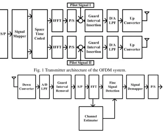
A. The OFDM System
The OFDM system used in the case study is obtained from [11]. The OFDM
system blocks. Fig. 1 and Fig. 2 depict the transmitter and receiver architecture part
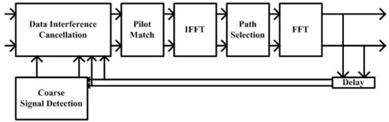
of the system, respectively. Fig. 3 deeply depicts the channel estimator block of the
receiver architecture. In this project, we use the OFDM system as a case study of
the bitwidth optimization problem.
Fig. 1 Transmitter architecture of the OFDM system.
Fig. 3 Channel estimator of the OFDM system. B. Fast Fourier Transform Overview
Fast Fourier Transform (FFT) and Inverse Fast Fourier Transform (IFFT) are
widely used algorithms for calculating the Discrete Fourier Transform (DFT) and
Inverse Discrete Fourier Transform (IDFT) because of the low computation
complexity. FFT processor is an important block in communication system and
signal processing system. For example, as shown in Fig. 4, Orthogonal Frequency
Division Multiplexing (OFDM) system is widely used in many communication
applications such as xDSL modem, HDTV, and wide band mobile terminals. In
those applications, FFT and IFFT are the most important processing blocks to meet
the design constraints.
C. Multiple Constant Multiplications Overview
Meanwhile, in many digital signal processing (DSP) algorithms, multiplication
is an essential operation. For example, the inputs of an N-taps finite impulse
response (FIR) filter are multiplied by N-1 coefficients. Note that the architecture
that multiplies the input by a set of coefficient is also known as multiple constant
multiplications (MCM). Since the multiplier is an expansive computational unit in
hardware implementation and the coefficients are mostly constant in filter design,
the multiplication can be implemented by s series of binary shifts and
adders/subtractors, instead of a generalized multiplier. For example, the constant
multiplication y = 5 * x can be computed as y = (x << 2) + x. The multiplier is
replaced by a 2-bit shifter and an adder. Compared to a generalized multiplier, it
reduces the hardware cost significantly. Thus, in typical digital filter designs,
multiplier-less MCM is widely adopted to avoid using the costly multiplication and
provide a high area-efficient filter design.
三、 研究方法及成果
A. A SystemC-based bitwidth optimization case study 1) Fixed Point Bit Width Determination
In digital system, there are two numeric representations, floating point and
fixed point. Floating point representation allocates one sign bit and a fixed number
of bits to exponent and mantissa. In fixed point representation, the bit width is
divided for the integer part and the fraction part. When designers develop
high-level algorithms, floating-point formats are usually used because of its
accuracy. Floating point representation can present very large range. In hardware,
the floating point representation needs to normalize the exponents of the operands
and it costs lots of hardware. Floating point representation is usually transferred to
As mentioned above, fixed point representation is composed of the integer part
and the fraction part. The number of bits assigned to the integer part is called
integer bit width (IBW), and the number of bits assigned to the fraction part is
called fraction bit width (FBW). The complete fixed point bit width can be
represented as:
BW = IBW + FBW (1)
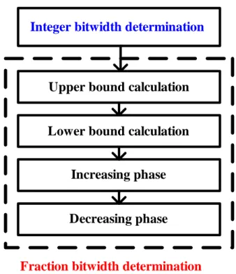
Fig. 5 Flow of bit width determination.
The total bitwidth determination procedure is showed in Fig. 5. First of all, the
integer bit width is calculated to prevent overflow. Then, the iteration procedure is
used to minimize the fraction bit width to reduce the total hardware cost.
The integer bit width has to be long enough to prevent overflow. By
monitoring the signals of the system, the minimum and the maximum value of the
signals are obtained, and the integer bit width can be also obtained.
Integer bit width = log2 (max (|MAX|, |MIN|)) + 2 (2)
Integer bitwidth determination
Upper bound calculation
Lower bound calculation
Increasing phase
Fraction bitwidth determination
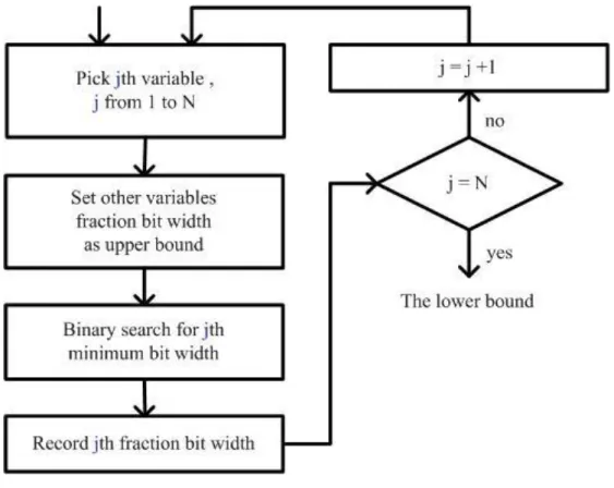
After assigning the integer bit width, there are three steps to determine the
fraction bit width. First, the uniform fraction bit width is determined to be the upper
bound of the algorithm. Second, the individual minimum bit width of every
variable is calculated to be the lower bound. Finally, the bit width will be fine tuned
between the upper bound and the lower bound for each variable. 2) Upper Bound Determination
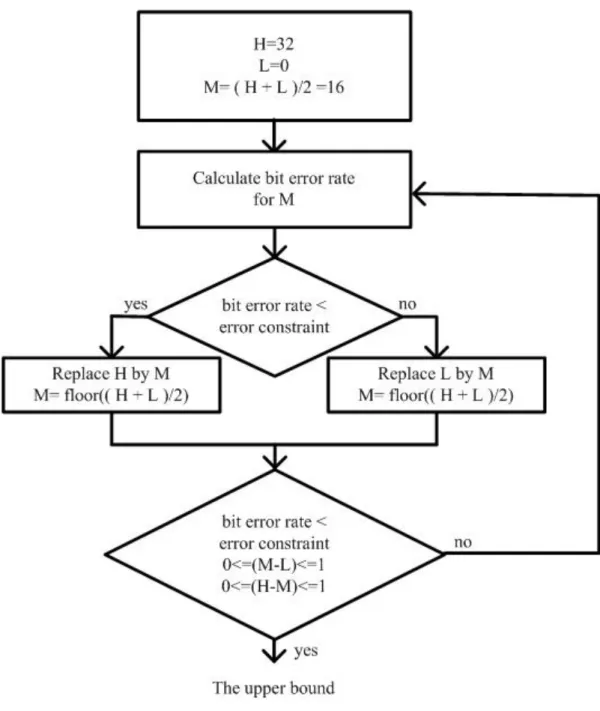
In order to accelerate the fraction bit width determination procedure, the
uniform fraction bit width is calculated to be the upper bound. The uniform fraction
bit width means that every variable has the same fraction bit width. A binary search
approach is used to quickly obtain the uniform fraction bit width.
Upper-Bound-Determination ( UB, error_ constraint )
begin
1. Set H to highest bit width and set L to lowest bit width, M = ( H + L)/2;
2. Calculate the BER for all variables having the M fraction bits;
3. While ( !(( BER < error_constraint ) and (0 ≤ M-L ≤ 1) and (0≤ H-M ≤1) ) )
4. if (BER < error_constraint )
5. replace H by M, M = floor (( H + L)/2 );
6. else replace L by M, M = floor(( H + L)/2 );
7. Calculate the BER for all variables having the M fraction bits;
8. for ( j from 1 to N )
9. UB[j] ← M;
10. return UB;
Fig. 6 Upper bound of the algorithm
The uniform fraction bit width determination procedure is showed in Fig. 6.
The fraction bit width determination procedure will repeat until it meets the
condition. We obtain a uniform bit width set which is denoted by UB and the upper
bound of every variable. The upper bound of the jth variable is denoted by wj_UB.
Because the fraction bit width determination procedure uses binary search approach,
3) Lower Bound Determination
In order to minimize the total hardware cost, it has to determine the minimum
individual fraction bit width when other variables remain as upper bound. The
individual minimum fraction bit width will be the lower bound, and the fine tuning
process will start from the lower bound.
Lower-Bound-Determination ( W, UB, LB, error_constraint )
begin
1. for ( i from 1 to N)
2. for ( j from 1 to N )
3. if ( j != i ) Set WLB[j]as UB[j];
4. LB[i] ← minimum_bit_width( WLB, error_constraint);
5. return LB;
Fig. 7 Lower bound of the algorithm
The lower bound determination procedure is showed in Fig. 7. We only choose one
variable and set the variable to fixed point each time, while other variables remain as upper
bound. We use the binary search to find the minimum bit width of the variable. We determine
every variable in order and finally obtain a lower bound bit width set, which is denoted by LB.
The lower bound of jth variable is denoted by wj_LB.
Because the determination procedure uses the binary search for the minimum individual
fraction bit width as well, the minimum individual fraction bit width, which will be the start
point of fine tuning process, is obtained quickly.
B. An Expandable MDC-based FFT generator 1) Motivations of the Expandable FFT Architecture
An exhaustive search approach is proposed to find all possible FFT architectures and then
generate a set of acceptable FFT architecture according to the design constraints. However,
from Table 1, we can find that all the possible solutions have the same number of multipliers,
number of adders and number of registers usage under the throughput constraint. Table 1 Comparison of hardware cost and throughput
FFT Length multipliers adders registers throughput
N jk 2jk N 2
log jk
Pease architecture bases on the radix-2 algorithm. Observing the raidx-2 flow graph, each
butterfly is followed by a multiplication operation at the output of subtraction operation.
Therefore, Pease architecture is a very regular architecture. However, the radix-2 algorithm
contains many trivial multiplications which do not need multipliers to calculate. For example,
multiplication of –j involves only real-imaginary swapping and sign inversion, as shown in Fig.
8.
Fig. 8 Illustration of –j multiplication
The radix-22 algorithm considers the multiplication of –j and merges the multiplication of –j
into odd-numbered columns. And the architecture of radix-22 algorithm contains two kinds of
butterflies, BFI and BFII. From the view of architecture, the radix-22 algorithm is more irregular
than the radix-2 algorithm.
The R22MDC is a pipeline architecture that implements the radix-22 algorithm with
throughput 2
N , so R2 2
MDC architecture is more irregular than Pease architecture. In the
following subsections, we introduce how we make the tradeoff between hardware and
throughout based on R22MDC and R2MDC architecture. 2) R22MDC Expansion Architecture
A general form of R22MDC vertical expansion architecture is shown in Fig. 9. Parameter N
indicates the FFT transform size, where N = 2m, where m is a natural number. Parameter t
indicates the degree of parallelism, where
1
1, 2, 4..., 2
m
t . The number of registers of each
original R22MDC architecture decreases as the degree of parallelism increases, and the number of
interconnection permutation matrix also increases. With the interconnection permutation matrix,
0 1 2 -2 -1 j 2j -2j -j Z Zj Zj2 = -Z Zj3 = -Zj
4
(2 log - 2)
t N
, the number of adders is 2 logt 2N , the number of registers is N 2t and
the throughput is 2t
N .
Fig. 9 General form of R22MDC vertical expansion architecture.
Fig. 10 shows the case when t =1, the original R22MDC architecture, the number of
multiplier is 2, the number of adders is 8, the number of registers of datapath is 14, and the
throughput is 1 8.
Fig. 10 Example of R22MDC vertical expansion architecture for t=1
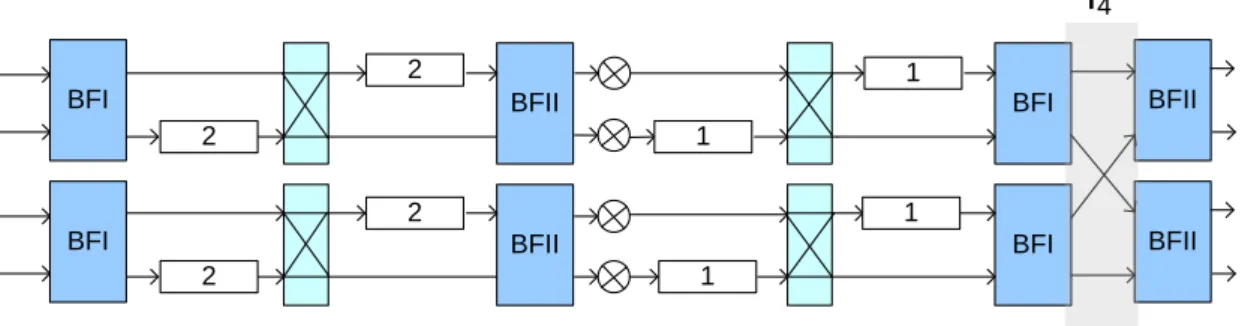
Fig. 11 shows the case when t =2, the number of multipliers is 4, the number of adders is
16, the number of registers of datapath is 12, and the throughput is1 4 .
Fig. 11 Example of R22MDC vertical expansion architecture for t=2
Fig. 12 shows the case when t =4, the number of multipliers is 8, the number of adders is
32, the number of registers of datapath is 8, and the throughput is1 2 .
BFII
BFI BFI BFII BFI BFII
BFII
BFI BFI BFII BFI BFII
BFI BFI BFII BFII L2t BFI BFI BFII BFII Lt Lt Lt/2 Lt/2 Lt/2 Lt/2 L4 L4 16 N t 8 N t 4 N t 1 16 N t 8 N t 4 N t 1
BFI 4 BFII BFI BFII
4 2
2
1
1
BFI BFII BFI BFII
BFI BFII BFI BFII 2 2 2 2 1 1 1 1
I4
Fig. 12 Example of R22MDC vertical expansion architecture for t=4
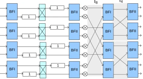
Fig. 13 shows the case when t =8, namely, a fully parallelized R22MDC vertical
expansion architecture, the number of multipliers is 16, the number of adders is 64, the number
of registers of datapath is 0, and the throughput is 1.
Fig. 13 Example of R22MDC vertical expansion architecture for t=8.
BFI BFII BFI BFII
BFI BFII BFI BFII
BFI BFII BFI BFII
BFI BFII BFI BFII
1 1 1 1 1 1 1 1 I4 I8
BFI BFII BFI BFII
BFI BFII BFI BFII
BFI BFII BFI BFII
BFI BFII BFI BFII
BFI BFII BFI BFII
BFI BFII BFI BFII
BFI BFII BFI BFII
BFI BFII BFI BFII
I8
C. Bitwidth-aware FIR filter design 1) The proposed design flow
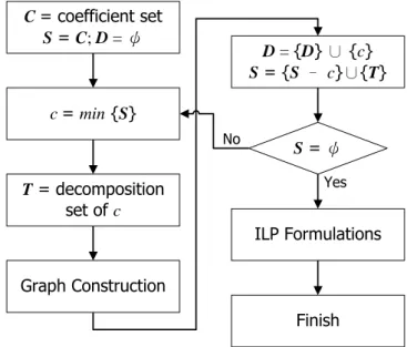
The flow diagram of our proposed bitwidth-aware ILP-based MCM algorithm is shown in
Fig. 14. To begin with, some preliminary notations are specified.
• C: the set of coefficients to be synthesized. It is also the outputs of MCM.
• S: the set of coefficients and subexpressions to be decomposing.
• R: a set that collects all resultant subexpressions of C.
• rn: a coefficient in R with the value of n.
• rs: the smallest coefficient in S.
• Tn: the set that collects all subexpressions of rn.
• Bn: the set that records the adder cost (in terms of bitwidth) to producing rn.
Fig. 14 The proposed algorithm flow
First, all coefficients are read into the coefficient set, C, and the decomposing
subexpression set, S. At beginning, the resultant set, R, should be empty. And then the smallest
coefficient, rs, is picked up from S as the decomposition candidate. Based on the specified digit
representation, i.e. pure binary, CSD, or MSD, all of the subexpressions of rs can be explored.
In the following discussion, we only demonstrate the CSD representation for example.
S = ψ D = {D} ∪ {c} S = {S – c}∪{T} Graph Construction T = decomposition set of c c = min {S} C = coefficient set S = C; D = ψ ILP Formulations Yes No Finish
Tn is the set that record the decomposition information of rn. After collecting all
subexpressions, Tn would be checked to see if any subexpression cannot be got by simply
shifting the input or the subexpressions in R. The coefficients that need to further decompose
are stored into S. Thus, S collects all subexpressions that need more adders to implement. The
process is iteratively executed until all coefficient are decomposed (i.e., S is empty).
After exploring the subexpressions, we use a graph-based approach to record the complete
relationship. Based on the subexprssion graph, the corresponding adder cost can be calculated
and stored in to Bn. The details of adder cost calculation will be introduced later. Finally, the
corresponding ILP formulations can be generated to get the minimal total bitwidth MCM
design. Based on the graph based approach, the bitwidth of the filter coefficient is not
necessary to constraint less than a specified bitwidth.
2) ILP modeling
The bitwidth-aware multiplier-less MCM problem is modeled into an ILP formulation to
minimize the total number of bitwidth. Two constraints are developed: 1) bitwidth constraints
show the adder bitwidth choice for each subexpression and 2) decomposition constraints
preserve the relationship between subexpressions.
a) Bitwidth constraints
For a coefficient that has only two non-zero digits, it can be directly implemented by one
adder. However, the constant variable can be implemented by more than one configuration
with different hardware cost if it has more than two non-zero digits. Amount those different
decomposition configurations; we use bitwidth constraint to choose one to realize the
coefficient. The following constraints are applied:
} { max n,w B w n a r n (3)
For example, according to Eq. (6), the bitwidth constraints for coefficient 21 is
} , max{ 21,8 21,11
21 a a
b) Decomposition constraints
Similarly, a coefficient can be implemented with various configurations, among which
would result in different hardware cost in terms of adder bitwidth. We use the decomposition
constraints to select the proper subexpressions.
}} , {min{ max , , a b T b a w r r r a n (5)
For example, coefficient 21 can be calculated in two configurations which require an
11-bit adder (i.e., 21152212217). Thus, the decomposition constraint of 21 with 11-bit adder can be given
} , max{ }} , min{ }, , max{min{ 17 5 17 1 5 1 11 , 21 r r r r r r a
c) Minimal total bitwidth objective function
As stated above, the total bitwidth of the MCM design can be calculated by summing the
bitwidth of each adder. The objective function of ILP formulation to minimize the total number
of adder bit is written as:
minimize
) ( , n B W w S n w n w a (6) d) Experimental ResultsWe present the experimental results illustrating the impact of our proposed bitwidth-aware
algorithm by comparing with [45]. Our experimental experiment is built on a GNU/Linux
workstation with two Intel Xeon 2.4 GHz processors and 12 GB main memory. In our design
examples, we use the Remez algorithm in MATLAB to randomly generate 12 128-tap FIR
filters including low pass, high pass, band pass, and band stop. For each filters, two kinds of
coefficient bitwidth are also evaluated (i.e., 12-bit and 16-bit). Besides, we also assume that the
bitwidth of input data is the same as the coefficient bitwidth. The generated ILP models are
solved with Gurobi Optimizer [51]. We also generate the corresponding Verilog RTL design
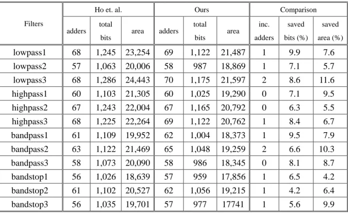
As shown in Table III, “adders” means the total number of adders in the filter, “total bits”
is the total number of adder bits, and “area” is the synthesis results in term of
NAND2-equavilent gate count. In the case of lowpass1, it requires 68 adders with 1245 bits in
total in the generated filter of [45]. Although our proposed algorithm may produce a solution
with more adders (only one more adder is required in this case), the total number of bit is saved
about 9.9%. Compared to the previous work, the synthesis results also show that the area of
our produced RTL filter design is saved about 7.6%. Besides, all of these 12 filters can be
solved in less than an hour of CPU time. The solution time is affordable in current filter design.
Thus, even though the proposed algorithm increases the total number of adders, it can provide
an area-efficient filter design.
Table 2 Experimental result of 128-tap filters
Filters
Ho et. al. Ours Comparison
adders
total
bits area adders
total bits area inc. adders saved bits (%) saved area (%) lowpass1 68 1,245 23,254 69 1,122 21,487 1 9.9 7.6 lowpass2 57 1,063 20,006 58 987 18,869 1 7.1 5.7 lowpass3 68 1,286 24,443 70 1,175 21,597 2 8.6 11.6 highpass1 60 1,103 21,305 60 1,025 19,290 0 7.1 9.5 highpass2 67 1,243 22,004 67 1,165 20,792 0 6.3 5.5 highpass3 68 1,225 22,264 69 1,122 20,762 1 8.4 6.7 bandpass1 61 1,109 19,952 62 1,004 18,373 1 9.5 7.9 bandpass2 63 1,122 21,469 65 1,048 19,259 2 6.6 10.3 bandpass3 58 1,073 20,090 58 986 18,345 0 8.1 8.7 bandstop1 56 1,026 18,639 57 959 17,856 1 6.5 4.2 bandstop2 61 1,102 20,527 62 1,056 19,215 1 4.2 6.4 bandstop3 56 1,035 19,701 57 977 17741 1 5.6 9.9
四、 結論與討論
In this project, we proposed three techniques to deal with the bitwidth problem in
electronic system level design flow. 1) an autoquantization algorithm that uses the lower bound
and the upper bound to find the optimized bit width for the OFDM system, 2) an automatic
MDC-based FFT generator to design a specified FFT processor, and 3) a bitwidth-aware MCM
algorithm to minimize the total number of adder bits.
According to the simulation results, the proposed algorithm can reduce almost 30%
simulation times than CDM and sequential search. The proposed autoquantization algorithm is
almost ten times faster than the previous work. Besides, in our proposed FFT generator, only
the best FFT architecture is generated under the user-specified throughput constraint to reduce
the computation time in our proposed FFT generator. Compared with the Pease architecture,
for the length of 256 and 1024 cases, the generated FFT processor saves about 30.8% area
under throughput constraints. The experimental results also show that the proposed
bitwidth-aware MCM algorithm minimizes the total number of adder bits, which reduces about
7% hardware resource than existing algorithms.
五、 參考文獻
[1] H. Keding, M. Willems, M. Coors, and H. Meyr, “FRIDGE: a fixed-point design and simulation environment,” in Proceedings of IEEE Design, Automation and Test in Europe, 1998, pp. 429–435.
[2] G. A. Constantinides and G. J. Woeginger, “The complexity of multiple wordlength assignment,” Applied Mathematics Letter, pp. 137–140, 2002.
[3] C.Fang, R. Rutenbar, and T. Chen, “Fast, accurate static analysis for fixed-point finite-precision effects in DSP designs,” IEEE/ACM International Conference on Computer-Aided Design, 2003, pp. 275–282.
[4] D. Lee, A. Abdul Gaffar, R. Cheung, O. Mencer, W. Luk, and G. Constantinides, “Accuracy-guaranteed bit-width optimization,” IEEE Trans. Computer-Aided Design Integrated Circuits and Systems, vol. 25, no. 10, pp. 1990–2000, Oct. 2006.
[5] W. Osborne, R.C.C. Cheung, J. Coutinho, and W. Luk, “Automatic accuracy guaranteed bit-width optimization for fixed and floating-point systems,” IEEE International Conference on Field-Programmable Logic and Applications (FPL), 2007, pp. 617–620.
finite-precision effects in DSP applications via affine arithmetic modeling,” Proceedings of Design Automation Conference, 2003, pp. 496–501.
[7] H. Choi and W. P. Burleson, “Search-based wordlength optimization for VLSI/DSP synthesis,” IEEE Workshop on VLSI Signal Processing, VII, 1994, pp. 198–207.
[8] W. Sung and K. I. Kum, “Simulation-based word-length optimization method for fixed-point digital signal processing systems,” IEEE Transactions on Signal Processing, vol. 43, no. 12, pp. 3087–3090, 1995.
[9] J. Babb, M. Rinard, C.A. Moritz, W. Lee, M. Frank, R. Barua, and S. Amarasinghe, “Parallelizing applications into silicon”, IEEE Symposium on Field-Programmable Custom Computing Machines, 1999, pp.70–80.
[10] S. Roy and P. Banerjee, “An algorithm for trading off quantization error with hardware resources for MATLAB based FPGA design,” IEEE Transactions on Computers, vol. 54, no. 7, pp. 886–896, 2005.
[11] A. Mallik, D. Sinha, H. Zhou, and P. Banerjee, “Low power optimization by smart bit-width allocation in a SystemC based ASIC design environment,” IEEE Transactions on Computer Aided Design of Integrated Circuits, vol. 26, no. 3, pp. 447–455, 2007.
[12] M.L. Ku and C.C. Huang “A complementary codes pilot-based transmitter diversity technique for OFDM systems,” IEEE Transactions on Wireless Communication, vol. 5, no.3, pp. 504-508, 2006.
[13] K. Han and B.L. Evans, “Optimum wordlength search using sensitivity information,” EURASIP Journal on Applied Signal Processing, vol. 2006, pp. 1–14, 2006
[14] K. Han, I. Eo, K Kim, and H. Cho, “Numerical word-length optimization for CDMA demodulator,” IEEE International Symposium on Circuits and Systems, 2001, pp.290-293.
[15] SystemC 2.0.1 Language Reference Manual [online]. Available: http://www.systemc.org.
[16] Synopsys Inc., CoCentric SystemC Compiler Behavioral Modeling Guide [online]. Available: http://www.synopsys.com
[17] Synopsys Inc., CoCentric Fixed-Point Designer Datasheet [online]. Available: http://www.synopsys.com
[18] J. W. Cooley and J. W. Turkey, “An algorithm for machine computation of complex fourier series,” Math. Computation, vol. 19, pp. 297-301, 1965.
[19] L. R. Rabiner and B. Gold., Theory and application of digital signal processing. Prentice-Hall, Inc., 1975.
[20] E. H. Wold and A. M. Despain, “Pipeline and parallel-pipeline FFT processors for VLSI implementation,” IEEE Transactions on Computers, vol. 33, no. 5, pp. 414–426, 1984.
on Computers, vol. C-23, no. 10, pp. 993–1001, 1974.
[22] S. He and M. Torkelson, “A new approach to pipeline FFT processor,” International Proceedings of Parallel Processing Symposium, 1996, pp.766–770.
[23] R. Storn. “Radix-2 FFT-pipeline architecture with reduced noise-to-signal ratio,” IEE Proceedings on Vision, Image and Signal Processing, vol. 141, no. 2, pp.81–86, 1994.
[24] S. He and M. Torkelson, “Designing pipeline FFT processor for OFDM (de)modulation,” International Symposium on Signals, Systems, and Electronics, 1998, pp. 257–262.
[25] P. Duhamel, H. Hollmann, “Split radix FFT algorithm,” Electronics Letters, vol. 20, pp.14–16, 1984.
[26] D. Takahashi, “An extended split-radix FFT algorithm,” IEEE Signal Processing Letters, vol. 8, no. 5, pp. 145–147, 2001.
[27] G. Nordin, P. A. Milder, J. C. Hoe, and M. Püschel, “Automatic generation of customized discrete Fourier transform IPs,” Proceedings of Design Automation Conference, 2005, pp. 471–474.
[28] P. A. Milder, M. Ahmad, J.C. Hoe, and M. Püschel, “Fast and accurate resource estimation of automatically generated custom DFT IP cores, ” Proceeding of the ACM/SIGDA International Symposium on Field Programmable Gate Arrays, 2006, pp. 211–220.
[29] P. A. Milder, F. Franchetti, J. C. Hoe, and M. Püschel, “Formal datapath representation and manipulation for implementing DSP transforms, ” Proceeding of Design Automation Conference, 2008, pp. 385–390.
[30] J. Takala, T.Jarvinen, P. Salmela, and D. Akopial, “Multi-port interconnection networks for radix-r algorithms,” Proceeding of IEEE International Conference Acoustics, Speech, Signal, and Processing, 2001, pp. 1177–1180.
[31] Synopsys DesignWare [Online]. Available: http://www.synopsys.com .
[32] MATLAB [Online]. Available: http://www.mathworks.com .
[33] R.C. Singleton, “An algorithm for computing the mixed radix fast Fourier transform,” IEEE Transactions on Audio and Electroacoustics, vol. 1, no. 2, pp. 93–103, 1969.
[34] C.-Y. Wang, C.-B. Kuo, and J.-Y. Jou, “Hybrid word-length optimization methods of pipelined FFT processors,” IEEE Transactions on Computers, vol. 56, no. 8, pp. 1105–1118, 2007.
[35] P.D. Welch, “A fixed-point fast Fourier transform error analysis,” IEEE Transactions on Audio Electroacoustics, vol. 17, pp. 151–157, 1969.
[36] A. Pomerleau, H.L. Buijs, and M. Fournier, “A two-pass fixed point fast Fourier transform error analysis,” IEEE Transaction on Acoustics, Speech, and Signal Processing, vol. 25, pp.
[37] P. Cappello and K. Steiglitz, “Some complexity issues in digital signal processing,” IEEE Transactions on Acoustics, Speech, and Signal Processing, vol. 32, pp. 1037–1041, 1984. [38] N. Sidahao, G.A. Constantinides, and P.Y.K. Cheung, “A heuristic approach for multiple
restricted multiplication,” IEEE International Symposium on Circuits and Systems, 2005, pp. 692–695, 2005.
[39] D. Bull and D. Horrocks, “Primitive operator digital filters,” IEE Proceedings on Circuits, Devices and Systems, vol. 138, pp. 401–412, 1991.
[40] C.-Y. Yao, H.-H. Chen, T.-F. Lin, C.-J. Chien, and C.-T. Hsu, “A novel common-subexpression-elimination method for synthesizing fixed-point FIR filters,” IEEE Transactions on Circuits and Systems I, vol. 51, pp. 2215–2221, 2004.
[41] R. Pasko, P. Schaumont, V. Derudder, S. Vernalde, and D. Durackova, “A new algorithm for elimination of common subexpressions,” IEEE Transactions on Computer-Aided Design of Integrated Circuits and Systems, vol. 18, no. 1, pp. 58–68, 1999.
[42] R. Hewlitt and E. Swartzlantler, “Canonical signed digit representation for FIR digital filters,” IEEE Workshop on Signal Processing Systems, 2000, pp. 416–426.
[43] L. Aksoy, E. da Costa, P. Flores, and J. Monteiro, “Exact and approximate algorithms for the optimization of area and delay in multiple constant multiplications,” IEEE Transactions on Computer-Aided Design of Integrated Circuits and Systems, vol. 27, no. 6, pp. 1013–1026, 2008.
[44] Y.A.Ho, C. Lei, H. Kwan, and N. Wong, “Optimal common sub-expression elimination algorithm of multiple constant multiplications with a logic depth constraint,” IEICE transactions on Fundamentals of Electronics, Communications, and Computer Sciences, vol. E91-A, no.12, pp. 3568–3575, 2008.
[45] Y.A. Ho, C. Lei, H. Kwan, and N. Wong, “Global optimization of common subexpressions for multiplierless synthesis of multiple constant multiplications,” IEEE Asia and South Pacific Design Automation Conference, 2008, pp. 119–124.
[46] O. Gustafsson and L. Wanhammar, “ILP modeling of the common subexpression sharing problem,” International Conference on Electronics, Circuits and Systems, 2002, pp. 1171–1174.
[47] Y. Wang and K. Roy, “CSDC: a new complexity reduction technique for multiplierless implementation of digital FIR filters,” IEEE Transactions on Circuits System I, vol. 52, no. 9, pp. 1845–1853.
[48] R. Mahesh and A. Vinod, “New reconfigurable architectures for implementing FIR filters with low complexity,” IEEE Transactions on Computer-Aided Design of Integrated Circuits and Systems, vol. 29, no. 2, pp. 275–288, 2010.
[50] P. J. Downey, R. Sethi, and R. E. Tarjan, “Variations on the common subexpression Problem,” Journal of ACM, vol. 27, no. 4, pp. 758–771, 1980.
六、 計畫成果自評
In this project, we have developed:
1) A new algorithm that uses the lower and upper bound to find the optimized bit width
2) A SystemC-based simulation environment for OFDM system development
3) An expandable multipath delay commutator based FFT architecture
4) An FFT generator to produce a synthesizable FFT core under a given throughput constraint
5) A bitwith-aware MCM algorithm to minimize the total number of adder bitwith.
在計畫的研究成果未來將能技術移轉運用於產業界,提升研究的實用價值。雖然,期
刊論文的發表進度稍有落後,但是,嚴謹的審查過程,更能確保發表論文的品質。另外,
本計畫亦培育多位人才,共有七位博士班研究生、十三位碩士班研究生,目前均有很好的
發展。
Submitted journal articles
[1] Bu-Ching Lin, Ming-En Shih, Juinn-Dar Huang, and Jing-Yang Jou, “Scaling optimization for FFT processors using static probability-based analysis,” submitted to IEEE transaction on Computers.
[2] Bu-Ching Lin, Yao-Chung Hsu, Juinn-Dar Huang, and Jing-Yang Jou, “Delay and area optimal FIR filter synthesis using binary subexpression sharing,” submitted to IEEE Transactions on Computer-Aided Design of Integrated Circuits and Systems.
[3] Bu-Ching Lin, Juinn-Dar Huang, and Jing-Yang Jou “Bitwidth-aware multiple constant multiplication (MCM) synthesis for FIR filters,” submitted to IEICE Transactions on Fundamentals of Electronics, Communications, and Computer Sciences.
[4] Bu-Ching Lin, Jhih-Hong Lu, Juinn-Dar Huang, and Jing-Yang Jou “Delay optimal compressor tree synthesis for LUT-based FPGAs,” submitted to IEEE Transactions on Very Large Scale Integration Systems.
International conference proceedings
[1] Bu-Ching Lin, Yu-Hsiang Wang, Juinn-Dar Huang, and Jing-Yang Jou “Expandable MDC-based FFT architecture and its generator for high-performance applications,” Proceedings of IEEE International SoC Conference, 2010, pp. 188–192.
[2] Yu-Hsiang Kao and Juinn-Dar Huang, “High-performance NAND flash controller exploiting parallel out-of-order command execution,” Proceedings of IEEE International Symposium
Patent
[1] 黃俊達、呂智宏、林步青、周景揚, “應用於查找表式 FPGA 的壓縮樹延遲最佳化合成 演算法,” 中華民國專利申請案號 098144372, 98 年 12 月 23 日
[2] 黃俊達、王毓翔、林步青、周景揚, “可參數化管線式快速傳利葉轉換硬體產生器,” 中 華民國專利申請案號 099100407, 99 年 1 月 8 日
[3] Juinn-Dar Huang, Jhih-Hong Lu, Bu-Ching Lin, and Jing-Yang Jou, “Delay optimal compressor tree synthesis for LUT-based FPGAs,” US12/717,520, May 4, 2010
表一簡列近年本研究群的相關研究成果。94 年發表會議論文 11 篇,期刊論文 1 篇, 並於 IEEE 期刊發表 1 篇論文。95 年發表會議論文 3 篇,期刊論文 4 篇,並有 4 篇論文於 IEEE 期刊發表。96 年發表會議論文 3 篇,期刊論文 3 篇,並有 3 篇論於 IEEE 期刊會議論 文發表。97 年發表會議論文 1 篇,期刊論文 3 篇,並有 3 篇論於 IEEE 期刊會議論文發表, 98 年發表會議論文 1 篇,期刊論文 2 篇,並有 2 篇論於 IEEE 期刊會議論文發表。 Year Number of Papers
Domestic International SCI Conference Journal Conference Journal
2007 1 0 2 3 (IEEE: 2) 3 2008 0 0 1 3 (IEEE: 3) 3 2009 0 0 2 2 (IEEE: 2) 2 2010 1 0 1 3 (IEEE: 1) 2 2011 0 0 2 1 (IEEE: 1) 1 表一、本研究群近年相關研究成果
國科會補助專題研究計畫成果報告自評表
請就研究內容與原計畫相符程度、達成預期目標情況、研究成果之學術或應用價
值(簡要敘述成果所代表之意義、價值、影響或進一步發展之可能性)
、是否適
合在學術期刊發表或申請專利、主要發現或其他有關價值等,作一綜合評估。
1. 請就研究內容與原計畫相符程度、達成預期目標情況作一綜合評估
■達成目標
□ 未達成目標(請說明,以 100 字為限)
□ 實驗失敗
□ 因故實驗中斷
□ 其他原因
說明:本計畫提出三項技術以解決電子系統層級所遇到之位元數問題
2. 研究成果在學術期刊發表或申請專利等情形:
論文:□已發表 □未發表之文稿
■撰寫中 □無
專利:□已獲得
■申請中 □無
技轉:□已技轉 □洽談中
■無
其他:本計畫尚有四篇期刊論文待審,並有三件專利案申請中
3. 請依學術成就、技術創新、社會影響等方面,評估研究成果之學術或應用價
值(簡要敘述成果所代表之意義、價值、影響或進一步發展之可能性)(以
500 字為限)
於電子系統階層設計系統,能縮短硬體設計的流程,降低硬體設計的複雜度。在
本計畫中,我們提出使用複雜度資訊的自動化轉換浮點數到固定點數演算法,用
以縮小硬體複雜度並且同時減少模擬時間。並針對管線化的快速傅利葉轉換架構
提出了面積與通量折衷的方法,且能自動地產生對應的硬體設計。還針對數位濾
波器提出了一個考慮位元數的演算法,且能自動地產生對應的硬體設計。相較於
傳統只考慮運算單元的做法,能提供更有效率的硬體設計。在本計畫中,使用目
前業界尚不熟習之電子系統階層模擬軟體,由高階系統層次發掘並改善系統晶片
效能上所遇到之瓶頸,所培養之系統晶片設計人才,正是未來業界邁入多核心系
統晶片設計不可或缺的新血。
可供推廣之研發成果資料表 ■ 可申請專利 ■ 可技術移轉 日期:98 年 5 月 30 日
國科會補助計畫
計畫名稱:針對通訊數位訊號處理器之電子系統層級驗證與合成環 境(1/3) 計畫主持人:周景揚 計畫共同主持人:黃俊達 計畫編號:NSC 97-2220-E-009-039 學門領域:EW技術/創作名稱
正交多頻多工系統使用複雜度資訊之位元寬度決定法Bit Width Determination Using Complexity Information for OFDM System
發明人/創作人
周景揚、黃俊達技術說明
中文: 當設計正交多頻多工系統時,需要決定浮點數到固定點數的轉換, 目的為縮小硬體複雜度。我們提出使用複雜度資訊的自動化轉換浮 點數到固定點數演算法。同時考慮到了整數以及小數的位元寬度。 對整數的位元寬度來說,演算法決定需要多少位元寬度以避免溢 位。對小數位元寬度來說,我們提出的演算法使用上邊界以及下邊 界來得到最後的結果。我們的實驗結果顯示,所提出之演算法相較 於已知的做法減少大約 30%的摸擬時間。 英文:In OFDM system design, the conversion from floating point to fixed point is necessary to minimize the hardware complexity. An automatic algorithm using complexity information for the floating point to fixed point conversion is proposed. It considers both the integer bit width and the fraction bit width. For the integer bit width, the algorithm identifies numbers of the integer bit width to prevent the overflow. For the fraction bit width, the algorithm uses the lower bound and the upper bound to find the results. We apply the proposed algorithm to the OFDM system. The results show that the proposed algorithm reduces almost 30% simulation time than complexity-and-distortion measure and sequential search method.
可利用之產業
及
可開發之產品
產業: IC、通訊系統晶片設計公司 產品: 無線網路存取設備、手機技術特點
o 可降低硬體複雜度,減少系統設計成本 o 可加速正交多頻多工系統之開發推廣及運用的價值
o 加速 通訊系統晶片產品開發速度 o 降低通訊系統晶片的設計成本 ※ 1.每項研發成果請填寫一式二份,一份隨成果報告送繳本會,一份送 貴單位研 發成果推廣單位(如技術移轉中心)。 ※ 2.本項研發成果若尚未申請專利,請勿揭露可申請專利之主要內容。 ※ 3.本表若不敷使用,請自行影印使用。可供推廣之研發成果資料表 ■ 可申請專利 ■ 可技術移轉 日期:99 年 5 月 30 日
國科會補助計畫
計畫名稱:針對通訊數位訊號處理器之電子系統層級驗證與合成環 境(2/3) 計畫主持人:周景揚 計畫共同主持人:黃俊達 計畫編號:NSC 98-2220-E-009-039 學門領域:EW技術/創作名稱
高效能且低成本之可參數化快速傅利葉轉換硬體產生器A Parameterizable Generator for High-Performance and Low-Cost FFT Cores
發明人/創作人
周景揚、黃俊達技術說明
中文: 快速傅利葉轉換處理器相當廣泛的應用在訊號處理系統及通訊系 統中。雖然現存的文獻提供了許多快速傅利葉轉換處理器的架構, 但要能夠在給定的條件下挑選出最適合的架構仍是一個相當重要 的技術問題。一個快速傅利葉轉換處理器產生器,不但可以增加設 計的生產力,同時也可以縮短整個系統設計開發的時程。在這篇論 文中,我們針對管線化的快速傅利葉轉換架構提出了面積與通量折 衷的方法,且能自動地產生對應的硬體設計。實驗結果顯示,我們 在通量的限制之下,可以產生硬體面積較小的架構。 英文:The Fast Fourier Transform (FFT) processors are widely used in signal processing systems and communication systems. Many FFT architectures are proposed in literature to meet different applications. While designing an FFT processor, one of the most difficult issues is to choose the best architecture under the design constraints. An FFT generator can not only improve the productivity but also shorten time-to-market. In this thesis, we propose approaches which can make appropriate design trade-off between throughput and area of pipeline FFT architectures, and automatically generate the corresponding hardware design. The experimental results show that the proposed methodology can generate area-efficient architectures under throughput constraints.
可利用之產業
及
可開發之產品
產業: IC、通訊系統晶片設計公司 產品: 無線網路存取設備、手機技術特點
o 可降低硬體複雜度,減少系統設計時間 o 可加速快速傅利葉轉換處理器之開發推廣及運用的價值
o 加速通訊、多媒體系統晶片產品開發速度 o 降低系統晶片的設計成本 ※ 1.每項研發成果請填寫一式二份,一份隨成果報告送繳本會,一份送 貴單位研 發成果推廣單位(如技術移轉中心)。 ※ 2.本項研發成果若尚未申請專利,請勿揭露可申請專利之主要內容。可供推廣之研發成果資料表 ■ 可申請專利 ■ 可技術移轉 日期:100 年 5 月 30 日
國科會補助計畫
計畫名稱:針對通訊數位訊號處理器之電子系統層級驗證與合成環 境(3/3) 計畫主持人:周景揚 計畫共同主持人:黃俊達 計畫編號:NSC 99-2220-E-009-015 學門領域:EW技術/創作名稱
位元數保證之有限脈衝響應濾波器設計環境A bitwidth-aware FIR filter design environment
發明人/創作人
周景揚、黃俊達技術說明
中文: 多常數乘法器廣泛被應用在數位訊號處理上。在將輸入資料乘上一 組係數時,使用加法器/減法器和位移器取代掉通用的乘法器。雖 然已經有許多無通用乘法器的多常數乘法器演算被被提出,以減少 所使用的加法器/減法器個數。然而,在設計過程中,加法器/減法 器的位元數並沒有被考慮進去,而這資訊能更精確地反映所使用的 實際硬體資源。因此,我們提出一個位元數保證的濾波器設計演算 法。實驗結果顯示,所提出的演算法相較於已知的做法,能節省約 7%的硬體資源。 英文:The multiple constant multiplication (MCM) is extensively used in digital signal processing (DSP) applications, such as filters. It multiplies the input data with a set of coefficients by using adder/subtractors and binary shifters instead of generic multipliers. Though many multiplier-less MCM algorithm are proposed to minimize the total number of adders/subtractors, the adder bitwidth are not took into consideration which can reflect the hardware resource preciously. In this paper, we propose a bitwidth-aware MCM algorithm to minimize the total number of adder bits. The experimental results show that the proposed algorithm can minimize the total number of adder bits, which reduces about 7% hardware resource than existing algorithms.
可利用之產業
及
可開發之產品
產業: IC、通訊系統晶片設計公司 產品: 無線網路存取設備、手機技術特點
o 可降低硬體複雜度,減少系統設計時間 o 可加速濾波器之開發推廣及運用的價值
o 加速通訊、多媒體系統晶片產品開發速度 o 降低系統晶片的設計成本 ※ 1.每項研發成果請填寫一式二份,一份隨成果報告送繳本會,一份送 貴單位研 發成果推廣單位(如技術移轉中心)。 ※ 2.本項研發成果若尚未申請專利,請勿揭露可申請專利之主要內容。 ※ 3.本表若不敷使用,請自行影印使用。國科會補助計畫衍生研發成果推廣資料表
日期:2011/10/28國科會補助計畫
計畫名稱: 子計畫三:針對通訊數位訊號處理器之電子系統層級驗証與合成環境(3/3) 計畫主持人: 周景揚 計畫編號: 99-2220-E-009-015- 學門領域: 晶片科技計畫--整合型學術研究 計畫無研發成果推廣資料
99 年度專題研究計畫研究成果彙整表
計畫主持人:周景揚 計畫編號: 99-2220-E-009-015-計畫名稱:使用 60GHz 之室內十億級位元傳輸率之無線基頻傳收機--子計畫三:針對通訊數位訊號處 理器之電子系統層級驗証與合成環境(3/3) 量化 成果項目 實際已達成 數(被接受 或已發表) 預期總達成 數(含實際已 達成數) 本計畫實 際貢獻百 分比 單位 備 註 ( 質 化 說 明:如 數 個 計 畫 共 同 成 果、成 果 列 為 該 期 刊 之 封 面 故 事 ... 等) 期刊論文 0 0 100% 研究報告/技術報告 0 0 100% 研討會論文 0 0 100% 篇 論文著作 專書 0 0 100% 申請中件數 1 1 100% 專利 已獲得件數 0 0 100% 件 件數 0 0 100% 件 技術移轉 權利金 0 0 100% 千元 碩士生 6 5 100% 博士生 5 3 100% 博士後研究員 0 0 100% 國內 參與計畫人力 (本國籍) 專任助理 0 0 100% 人次 期刊論文 0 0 100% 研究報告/技術報告 0 0 100% 研討會論文 2 2 100% 篇 論文著作 專書 0 0 100% 章/本 申請中件數 2 2 100% 專利 已獲得件數 0 0 100% 件 件數 0 0 100% 件 技術移轉 權利金 0 0 100% 千元 碩士生 0 0 100% 博士生 0 0 100% 博士後研究員 0 0 100% 國外 參與計畫人力 (外國籍) 專任助理 0 0 100% 人次其他成果