= [2, 2, 2IT. The time instants when the measurement of the out- puts are successful are shown by 0 in Fig. lb.
By comparison of (i) and (ii), we can verify that the filter pro- posed in this Letter yields a better result than the continuous-dis- Crete filter that has a seemingly natural remedy to cope with the loss of the measurement data. This clearly shows the effectiveness of the use of our filter. The difference between (i) and (iii) shows the deterioration caused by the loss of the measurement data due to unreliable sampling.
0 IEE 1997
Electronics Letters Online No: 19970651
S. Tanaka, T. Hagiwara and M. Araki (Department of Electrical Engineering, Kyoto University, Yoshida-Honmachi, Sakyo-ku, Kyoto 606-01, Japan)
8 April I997
References
JAZWINSKI, A.H.: 'Stochastic processes and filtering theory' (Academic Press, 1970)
KALMAN, R.E., and BUCY, R.s.: 'New results in linear filtering and prediction theory', J. Basic Eng. Trans. ASME, 1961, 83, pp. 950- 1008
DEYST, J.J., and PRICE, C.F : 'Conditions for asymptotic stability of the discrete minimum-variance linear estimator', ZEEE Trans. Automatic Control, 1968, 13, (6), pp. 702-705
HAGIWARA, T., FUJIMURA, T., and ARAKI, M.: 'Generalized multirate- output controllers', Znt. J. Control, 1990, 52, (3), pp. 5977612
High input impedance voltage-mode
lowpass, bandpass and highpass filter using
current-feedback amplifiers
Jiun-Wei Horng and Maw-Huei Lee
Indexing terms: Active$lters, Current conveyors
A new configuration for realising high input impedance lowpass, bandpass and highpass filters simultaneously by using three current-feedback amplifiers, three grounded capacitors, three grounded resistors and one floating resistor is presented. The proposed circuit offers the following features: realisation of lowpass, bandpass and highpass signals from the same configuration, no requirements for component matching conditions, orthogonal control of & and Q, the use of grounded capacitors, low active and passive sensitivities and low output impedance.
Introduction: The applications and advantages in the realisation of active filter transfer functions using current-feedback amplifiers (CFAs) have received considerable attention [l - 61. This amplifier can provide not only constant bandwidth, independent of closed- loop gain, but also a high slew-rate capability. Moreover, it has a low-impedance output which makes the circuit cascadable without additional buffers [7]. Thus, it is beneficial to use a current-feed- back amplifier as a basic building block to realise various ana- logue signal-processing circuits. Liu [6] proposed a high input impedance configuration for realising bandpass, lowpass and high- pass filters. However, the filter functions (lowpass, highpass and bandpass) cannot be simultaneously realised, which implies the
b
v z
Fig. 1 Circuit symbol of current-feedback amplifier
ELECTRONICS LETTERS 22nd May 1630411
1997 Vol. 33
need to change the topology of the circuit. Conversely, two topologies of Liu's circuits [6] use floating capactors. In this Letter, a new configuration is proposed for realising high input impedance lowpass, bandpass and highpass filters simultaneously, by using three current-feedback amplifiers, three grounded capaci- tors, three grounded resistors and one floating resistor. Critical component matching conditions are not required in the design. The use of grounded capacitors makes the proposed circuit suita- ble for integrated-circuit implementation [8, 91. The output imped- ance of the proposed circuit is very small, so it is cascadable.
Circuit descriptions: The circuit symbol of a current-feedback amplifier (CFA) is shown in Fig. 1. This circuit is equivalent to a second-generation current conveyor [lo] with a voltage buffer [l I]. Its characteristics can be modelled as
0 0 0
[::I
=[
1 0 01 a n d v , = v , ( I )2, 0 1 0 w,
The proposed circuit is shown in Fig. 2. In this, three grounded capacitors are used in the design. The use of grounded capacitors is particularly attractive for integrated-circuit implementation [8, 91. Because the output impedance of terminal V, is very small, the three output terminals, Val, V,, and
K3,
can be directly connected to the next stage, respectively. The voltage transfer functions for the network of Fig. 2 can be expressed as(4)
v03 - S2
-
C RG R
v,n
s2 -k 'CzCtR3R5 -k C Z C ~ R ~ ~ R ~ R : ,Thus, the circuit realises a lowpass signal at Voi, a bandpass signal at V,, and a highpass signal at
F&,
simultaneously. Critical com- ponent matching conditions are not required in the design."I"
0
m
Fig. 2 New configuration for realising high input impedance lowpass,
bandpass and highpass filter using CFAs
Taking into account the nonideal CFAs, namely i, = ai,, v, =
pv,
and v,, = "IV,, wherea
= l k l and << 1) denotes the cur- rent tracking error of a CFA,p
= 1% and (& << l) is the input voltage tracking error, and y = I s , and E, (E, << 1) is the output voltage tracking error, the natural frequency Q, and quality factor Q are given byAll the active and passive sensitivities are low.
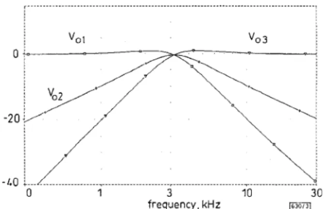
PSPICE simulations were carried out to demonstrate the feasi- bility of the proposed circuit. The current-feedback amplifiers were implemented using AD844s. The following setting was selected to obtain the lowpass, bandpass and highpass filters with unity gain at natural frequency& = 3183Hz and Q = 1: RI = R, =
R5 =
&
= 5kQ C, = C, = C, = 10nF. The simulation results are shown in Fig. 3.v o 1 vO 3
11 SVOBODA, J.A., MCGORY, L., and WEBB, s.: ‘Applications of a commercially available current conveyor’, Znt. J. Electron., 199 1,
70, pp. 159-164
Universal current-mode filter with reduced
number of active and passive components
S. Ozoguz and C . Acar
Indexing terms: Active Jilters, Current-mode circuits
A new current-mode (CM) universal active fdter with single-input and three-outputs (SITO) employing only four CCIIs and a
minimum number of passive components is presented. The proposed filter based on an RLC shunt circuit, has a good sensitivity performance and achieves the desired fdter characteristics without any component matching.
frequency, kHz
Fig. 3 Simulation results of Fig. 2 with unity gain at natural frequency
fo = 3183Hz and Q = I : R , = R3 = R, = R, = 5kQ C, = C, = C, =
lOnF
n
Vdb iR8:2)a
Vdb (R10:i)v
Vdb (R6:2)Conclusion: New high input impedance lowpass, bandpass and
highpass filters using three CFAs are presented. This filter pro- vides the following advantages: (i) the lowpass, highpass and bandpass fiter functions can be realised simultaneously without changing the circuit topology, (ii) there are no requirements for critical component matching conditions, (iii) there is orthogonal control of the filter’s natural frequency and quality factor, (iv) it has low active and passive sensitivities, (v) use of only grounded capacitors makes the circuit suitable for integrated-circuit imple- mentation and (vi) there is very low output impedance which makes the voltage-mode circuit cascadable.
0 TEE 1997
Electronics Letters Online No: 19970618
Jiun-Wei Horng and Maw-Huei Lee (Department of Electrical Engineering, Room 329, National Taiwan University, Taipei I061 7,
Taiwan, Republic of China)
E-mail: f%2076@cctwin.ee.ntu.edu.tw
17 March 1997
References
LIU, s.I., and HWANG, Y.s.: ‘Realisation of R-L and C-D impedances using a current-feedback amplifier and its applications’, Electron.
Lett., 1994, 30, pp. 380-381
FABRE, A.: ‘Gyrator implementation from commerically available transimpedance operational amplifiers’, Electron. Lett., 1992, 28,
FABRE. A.: ‘Insensitive voltage-mode and current-mode filters from commerically available transimpedance opamps’, IEE Proc. G,
CHANG, c.M., HWANG, c.s , and TU, S.H : ‘Voltage-mode notch, lowpass and bandpass filter using current-feedback amplifiers’,
Electron. Lett., 1994, 30, pp. 2022-2023
LIU, s.I., and wu, D s.: ‘New current-feedback amplifier-based universal biquadratic filter’, IEEE Trans. Instrumentation Measurement, 1995, 44, pp. 915-917
LIU, s.I.: ‘High input impedance filters with low component spread using current-feedback amplifiers’, Electron. Lett., 1995, 31, pp.
1042-1043
Analog Devices: ‘Linear products data book‘ (Nonvood MA, 1990)
BHuSAN, M., and NEWCOMB, R.w.: ‘Grounding of capacitors in integrated circuits’, Electron. Lett., 1967, 3, pp. 148-149
PAL, K., and SINGH, R.: ‘Inductorless current conveyor allpass filter using grounded capacitors’, Electron. Lett., 1982, 18, pp. 47 pp. 263-264
1993, 140, pp. 319-321
10 SEDRA, A., and SMITH, K.c.: ‘A second generation current conveyor and its applications’, IEEE Trans. Circuit Theory, 1970, 17, pp. 132-134
Introduction: It is a well-known fact that an RLC shunt circuit is a useful passive prototype for the realisation of universal CM SITO filters [l]. So far, several CCII based filters of t h s type whch are obtained by the classical simulation of ideal inductance (i.e. capac- itively-loaded gyrator [2]) have been proposed [l, 3, 41. However, it has been proved that the use of the simulated lossy inductors rather than ideal inductors generally leads to filters with a simpler structure [l, 5-71,
Considering this fact, in this Letter we present a new CM uni- versal SITO fiter which is obtained by the use of a new simulation of lossy inductance (parallel RL circuit), rather than by the simu- lation of ideal inductance L, in an RLC shunt circuit. As is expected, this approach yields a universal fdter with a minimum number of passive components, (i.e. two resistors and two capaci- tors) and a reduced number of active elements (only four CCIIs). This number of active elements is less than that of the other SITO filters [3, 6, 71 which each require five CCIIs (when the filters pro- vide three high impedance current outputs).
c
Fig. 1 Proposed CM universal biquadratic filterProposed circuit: Consider the circuit shown in Fig. 1. Clearly,
CCII, and CCII, are used to provide high impedance outputs for
I,, and Io*. The subcircuit in parallel with C,, consisting of RI, R,, C,, CCII, and CCII, constitutes a grounded parallel RL imped- ance. This parallel RL simulator realises an RLC shunt circuit along with C,.
-
The transfer functions realised by this filter can be given by __ (1) I o 1 - - S2 1 - s2 + $6 + KmzG and
Therefore, LP, BP and HP responses can be simultaneously obtained from this filter. Moreover, by interconnecting the z- terminals of the CCII, and CCII, from which I,, and I,, are