Cost-effective 33-Gbps intensity modulation
direct detection multi-band OFDM LR-PON
system employing a 10-GHz-based transceiver
Dar-Zu Hsu,1,2,* Chia-Chien Wei,3 Hsing-Yu Chen,2 Wei-Yuan Li,1 and Jyehong Chen11Department of Photonics, National Chiao-Tung University, Hsinchu, Taiwan, 300
2Information and Communications Research Labs, Industrial Technology Research Institute, Hsinchu, Taiwan, 300 3Department of Applied Materials and Optoelectronic Engineering, National Chi Nan University, Nantou, Taiwan,
545
Abstract: We develop a dynamic multi-band OFDM subcarrier allocation
scheme to fully utilize the available bandwidth under the restriction of dispersion- and chirp-related power fading. The experimental results successfully demonstrate an intensity-modulation-direct-detection 34.78-Gbps OFDM signal transmissions over 100-km long-reach (LR) passive-optical networks (PONs) based on a cost-effective GHz EAM and a 10-GHz PIN. Considering 0–100-km transmission bandwidth of a 10-10-GHz EAM, the narrowest bandwidth is theoretically evaluated to occur at ~40 km, instead of 100 km. Consequently, the performances of 20–100-km PONs are experimentally investigated, and at least 33-Gbps capacity is achieved to support LR-PONs of all possible 20–100-km radii.
©2010 Optical Society of America
OCIS codes: (060.2330) Fiber optics communications; (060.0060) Fiber optics and optical
communications.
References and links
1. T. Koonen, “Fiber to the home/fiber to the premises: what, where, and when?” Proc. IEEE 94(5), 911–934 (2006).
2. P. D. Townsend, G. Talli, C. W. Chow, E. M. MacHale, C. Antony, R. Davey, T. De Ridder, X. Z. Qiu, P. Ossieur, H. G. Krimmel, D. W. Smith, I. Lealman, A. Poustie, S. Randel, and H. Rohde, “Long Reach Passive Optical Networks,” in The 20th Annual Meeting of the IEEE Lasers and Electro-Optics Society, 2007. LEOS
2007 (IEEE-LEOS, 2007), pp. 868–869.
3. R. Lin, “Next generation PON in emerging networks,” in Optical Fiber Communication Conference and
Exposition and The National Fiber Optic Engineers Conference, OSA Technical Digest (CD) (Optical Society of America, 2008), paper OWH1.
4. R. P. Davey, D. B. Grossman, M. Rasztovits-Wiech, D. B. Payne, D. Nesset, A. E. Kelly, A. Rafel, S. Appathurai, and S. H. Yang, “Long-reach passive optical networks,” J. Lightwave Technol. 27(3), 273–291 (2009).
5. K. Y. Cho, K. Tanaka, T. Sano, S. P. Jung, J. H. Chang, Y. Takushima, A. Agata, Y. Horiuchi, M. Suzuki, and Y. C. Chung, “Long-reach coherent WDM PON employing self-polarization-stabilization technique,” J. Lightwave Technol. 29(4), 456–462 (2011).
6. D. Shea and J. Mitchell, “A 10 Gb/s 1024-way-split 100-km long-reach optical-access network,” J. Lightwave Technol. 25(3), 685–693 (2007).
7. N. Cvijetic, D. Qian, and J. Hu, “100 Gb/s Optical access based on optical orthogonal frequency-division multiplexing,” IEEE Commun. Mag. 48(7), 70–77 (2010).
8. U. H. Hong, K. Y. Cho, Y. Takushima, and Y. C. Chung, “Maximum reach of long-reach RSOA-based WDM PON employing remote EDFA,” in Optical Fiber Communication Conference, OSA Technical Digest (CD) (Optical Society of America, 2011), paper OMP1.
9. K. Y. Cho, B. S. Choi, Y. Takushima, and Y. C. Chung, “25.78-Gb/s Operation of RSOA for next-generation optical access networks,” IEEE Photon. Technol. Lett. 23(8), 495–497 (2011).
10. http://www.itu.int/rec/T-REC-G.987.1-201001-I/en
11. D. Z. Hsu, C. C. Wei, H. Y. Chen, J. Chen, M. C. Yuang, S. H. Lin, and W. Y. Li, “21 Gb/s after 100 km OFDM long-reach PON transmission using a cost-effective electro-absorption modulator,” Opt. Express 18(26), 27758– 27763 (2010).
12. A. Gharba, P. Chanclou, M. Ouzzif, J. L. Masson, L. A. Neto, R. Xia, N. Genay, B. Charbonnier, M. Hélard, E. Grard, and V. Rodrigues, “Optical transmission performance for DML considering laser chirp and fiber
dispersion using AMOOFDM,” in 2010 International Congress on Ultra Modern Telecommunications and
Control Systems and Workshops (ICUMT) (2010), pp. 1022–1026.
13. T. Watanabe, N. Sakaida, H. Yasaka, F. Kano, and M. Koga, “Transmission performance of chirp-controlled signal by using semiconductor optical amplifier,” J. Lightwave Technol. 18(8), 1069–1077 (2000). 14. H. S. Chung, Y. G. Jang, and Y. C. Chung, “Directly modulated 10-Gb/s signal transmission over 320 km of
negative dispersion fiber for regional metro network,” IEEE Photon. Technol. Lett. 15(9), 1306–1308 (2003). 15. Z. Liu, Y. Xin, and G. B. Giannakis, “Space-time-frequency coded OFDM over frequency-selective fading
channels,” IEEE Trans. Signal Process. 50(10), 2465–2476 (2002).
16. Z. Cao, J. Yu, W. Wang, L. Chen, and Z. Dong, “Direct-detection optical OFDM transmission system without frequency guard band,” IEEE Photon. Technol. Lett. 22(11), 736–738 (2010).
17. C. C. Wei, “Small-signal analysis of OOFDM signal transmission with directly modulated laser and direct detection,” Opt. Lett. 36(2), 151–153 (2011).
18. http://www.itu.int/dms_pub/itu-t/oth/06/13/T06130000200001PDFE.pdf
19. J. Wang and K. Petermann, “Small signal analysis for dispersive optical fiber communication systems,” J. Lightwave Technol. 10(1), 96–100 (1992).
20. F. Devaux, Y. Sorel, and J. F. Kerdiles, “Simple measurement of fiber dispersion of chirp parameter of intensity modulated light emitter,” J. Lightwave Technol. 11(12), 1937–1940 (1993).
1. Introduction
With the exponentially increasing of customer needs for broadband services, passive optical network (PON) is considered to be the most promising candidate that can economically provide high bandwidth to end-users [1]. Recently, there have been growing interests in the new type of optically amplified large-split long-reach PON (LR-PON) [2–6]. Integrated the access network with the metro network within the 100-km target range, LR-PON claims to considerably reduce the capital and operational expenditures by increasing the coverage of the central office and consolidating the O/E/O conversion interfaces inside the existing networks. Besides, LR-PONs can simplify the network hierarchies and thus reduce the network latency, which is very important for the real-time broadband services.
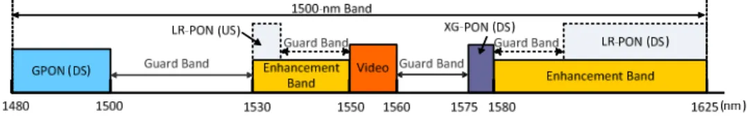
To realize next generation LR-PON systems, several multiplexing schemes are viable candidates to support more ONUs with higher data rate, such as time-division multiplexing (TDM), orthogonal frequency-division multiplexing (OFDM), and wavelength-division multiplexing (WDM). In particular, OFDM LR-PON, which boasts to offer high spectral efficiency and flexible bandwidth allocation, has attracted a lot of attention recently [7]. Both TDM and OFDM LR-PONs can easily support numerous ONUs by using an optical splitter with large splitting ratio and can broadcast the aggregated data to all ONUs on a single wavelength, thus have the benefit of simple wavelength management [6]. However, the aggregated data rate on a single wavelength will be very high (40 Gbps or higher), and each ONU has to process very high-speed aggregated data in order to receive and transmit a small portion of data (e.g. <1/128) [6]. In [7], a 108-Gbps OFDM PON over single wavelength is demonstrated employing two Mach-Zehnder modulators, polarization multiplexing and two receivers. For cost-sensitive ONUs, the proposed scheme will be too complicated and expensive to be a practical solution in the near future. An alternative solution is WDM LR-PON, where each ONU can be assigned a wavelength, thus ONUs doesn’t have to process the aggregated data and the speed requirement of each transceiver can be considerably lower. Besides, instead of using a large-splitting-ratio optical splitter, WDM LR-PON can use a wavelength multiplexer/demultiplexer (waveguide grating router, WGR), and the loss of WGR is much lower and insensitive to wavelength number. Unfortunately, even though the speed requirement of each transceiver is lower in a WDM system, numerous color transmitters are costly and undesired. To preserve the colorless upstream architecture, an RSOA (reflective semiconductor optical amplifier) is employed for upstream service [8,9]. Currently, employing RSOAs are still facing some technical challenges such as limited bandwidth, ASE noise, Rayleigh backscattering needed to be overcome. Besides, the systems fail to allocate bandwidth flexibly among ONUs of different wavelengths [4]. In particular, since a LR-PON is needed to be coexisted with the current PONs, such as 10-Gbps PON (XG-PON) and Gigabit PON (G-(XG-PON). As shown in Fig. 1 [10], excluding guard bands, the available enhancement bands provide very limited bandwidth at C-band for future LR-PONs. For the reasons stated above, a more practical solution will be a hybrid WDM/OFDM
LR-PON, which optimizes the trade-off between the number of wavelength channels and the cost of transceivers. For instance, if a cost-effective transceiver can provide 32-Gbps capacity, only four wavelength channels are required for each direction (downstream and upstream) to support a LR-PON with 128 ONUs and 1-Gbps data rate per ONU.
Fig. 1. Wavelength allocations of current G-PON/XG-PON and proposed LR-PON. (DS: downstream; US: upstream)
To reach the target transmission distance of up to 100 km, nonetheless, will require better performance and more expensive components. To further reduce costs, intensity-modulation-direct-detection (IMDD) is expected. Additionally, it is desirable to generate high-speed signals by low-bandwidth cost-effective transceivers, such as commercially matured 10-GHz directly modulated DFB lasers (DMLs) or electro-absorption modulated lasers (EMLs) and 10-GHz PIN detectors, assisted by spectrally efficient modulation format, such as quadrature amplitude modulation (QAM). Nonetheless, one critical drawback of DMLs or EMLs is the generated optical signal will be double-side band (DSB) and frequency-chirped, which will result in detrimental dispersion- and chirp-related power fading. As a result, after 100-km transmission over single-mode fiber (SMF), the bandwidth of the transmission system is limited to a few GHz [11,12]. Thanks to the advance in digital-signal-processing (DSP) technology, both power levels and modulation levels of OFDM subcarriers can be adaptively allocated to efficiently utilize very limited transmission bandwidth at baseband. Accordingly, our previous work has demonstrated that using 128-QAM and 3-GHz bandwidth to achieve a 21-Gbps LR-PON over 100-km SMF [11]. Moreover, to increase available transmission bandwidth, it has been proposed that modifying the chirp parameter of DMLs or EMLs to be negative [13] or replacing the deployed fibers by the negative-dispersion fibers [14]. These schemes, however, are too complicated and expensive to be feasible. Coded OFDM, which is a visible scheme to overcome fading in wireless systems [15], has been used to coped with power fading in SMF transmission [16], but at the cost of decreasing bandwidth efficiency and increasing complexity. Nonetheless, unlike wireless system, the fiber channel response is relatively stable, and power fading is periodic and predictable. Consequently, secondary low-fading bands have been proposed to carry supplementary OFDM subcarriers to achieve full utilization of transceiver bandwidth [12]. Nevertheless, within the range of 0–100 km, the lowest supporting data rate of 7 Gbps in [12] implies that the number of 1-Gbps ONU is restricted to only 7. Hence, to support 128 ONUs, 19 wavelength channels are required and this will reduce the channel spacing and increase difficulties in wavelength management.
In this work, utilizing a 10-GHz IMDD transmission system, we propose a dynamic multi-band OFDM subcarrier allocation scheme to avoid power fading effects in LR-PONs of up to 100 km. According to the different frequency responses of different SMF lengths, the power level and modulation level of each OFDM subcarrier are dynamically modified to maximize the transmission capacity. As such, this work successfully achieves a superior performance of 34.78 Gbps over 100-km SMF by economically using a 10-GHz EAM and a 10-GHz PIN. Compared with the earlier work in [11], the experimental results confirmed at least 57% increased of data rate after 100-km SMF transmission. Moreover, considering the 10-GHz bandwidth of the EAM, the narrowest available bandwidth within 100-km SMF transmission system does not occur at 100 km, but at ~40 km. As a result, this work also investigates the transmission capacities over all possible cover radii of (LR-) PONs, i.e. 20–100 km, to guarantee at least 33-Gbps obtainable capacity. Besides, subcarrier-to-subcarrier intermixing interference (SSII), which has been theoretically revealed to be harmful after transmission in [17], is also experimentally measured and discussed in this work. Finally, this experiment demonstrates a cost-effective LR-PON of up to 100 km, which can provide 1-Gbps data rate
to each of 32 ONUs. Moreover, the system could simply be upgraded to support 128 ONUs by using only four wavelengths for each direction (downstream and upstream). Thus, compared with the previous proposals of LR-PONs, our proposed 33-Gbps hybrid WDM/OFDM LR-PON optimizes the trade-off between the number of wavelength channels [2–6,8,9,12] and the cost of transceivers [7], based on cost-effective 10-GHz EML and PIN based IMDD scheme.
2. Criteria and transmission bandwidth of feasible IMDD LR-PONs
Section1 λ λλ λW+1 λ λλ λ1, Section2 SectionW Metro Edge Node
W G R λ λλ λk Legend:
WGR: Waveguide Grating Router Sectionk
ONUN-1 ONU1 W G R λ λλ λW+k λ λλ λW+2 λ λλ λ2, λ λλ λ2W λ λλ λW, λ λλ λW+k λ λλ λk, ONU2 10-GHz IMDD OLT EML/ DML PIN 128 Gbps 32 Gbps ONUN 10-GHz IMDD ONU EML/ DML PIN λ λλ λk λ λλ λW+k N=32 W=4 1 Gbps 1 Gbps Business Mobile/ Wireless 1 Gbps Residential 20~100 km Optical Splitter
Fig. 2. Proposed feasible architecture for a cost-effective LR-PON.
Based on the trade-off between wavelength channel number and transceiver cost and the requirements of next-generation PON (NG-PON) discussed in [18], some criteria have been contemplated for a feasible LR-PON. Though some of the proposed numbers are open to discussion and may change with the development of technologies, these are the important issues that need to be addressed prudently: (a) Sustainable symmetric data rate of each ONU is 1 Gbps for supporting future broadband multimedia services [18]; (b) Power splitting ratio (N) is 32 for a reasonable optical loss budget and the aggregated data rate on a single wavelength is ≥32 Gbps; (c) Supporting ONU number is ≥128for sharing the capital and operational expenditures; (d) Using WDM technology to stack four (W = 4) 32-Gbps PON, thus 128 (N W× =128) ONUs can be achieved by four wavelengths for each direction, and (e) Cost effective transceiver design is achieved by a 10-GHz IMDD scheme. Notably, four wavelengths for each direction (downstream and upstream) are recommended due to very limited wavelength resources, as shown in Fig. 1. Thus, the proposed architecture of a LR-PON and the corresponding parameters of the above criteria are illustrated in Fig. 2, and the proposed LR-PON can meet the requirements of NG-PON [18] by using a cost-effect and feasible architecture. Wavelength management of four channels is not technique challenging, but the most crucial part turns out to be achieving the expected data rate of >32 Gbps via a cost-effective transceiver. In particular, while the IMDD scheme is preferred, an optical OFDM signal is generated in the form of DSB. Namely, an electrical OFDM subcarrier will be translated into two conjugated optical subcarriers on both sides of an optical carrier. After transmission in fiber link, however, the residual dispersion destroys their conjugated property and results in a well-known power fading. Moreover, since an optical signal modulated by a DML or an EML is chirped, the additional phase modulation also weakens the conjugated property between subcarriers. Accordingly, both frequency chirp and fiber dispersion will affect the received power. Considering small-signal approximation, the received power, Pr, of
an OFDM subcarrier [17,19,20]
(
2)
2(
2 2 1)
r 1 cos 2 2 tan s,
where α is the chirp parameter, β2 is the group velocity dispersion (GVD) parameter (β2 = −21.66 ps
2
/km for SMF), L is the fiber length, f is the frequency of the electrical OFDM subcarrier, and Ps represents the received power without fading. Therefore, as the
residual dispersion increases such that | 2π β2 2Lf2 tan 1α| −
− approaches π / 2, the received
electrical subcarrier will suffer serious fading to fail signal detection. Equation (1) also indicates that positive chirp will make fading happen with lower positive residual dispersion (β2< ). In any case, frequency components that suffer from high power fading are not 0 suitable to carry subcarriers.
0 1 2 3 4 5 6 7 8 9 10 -30 -25 -20 -15 -10 -5 0 5 Frequency (GHz) S2 1 o f th e t ra n s m is s io n s y s te m ( d B ) 20 km 40 km 60 km 80 km 100 km
Fig. 3. Frequency responses of 20–100-km SMF transmissions.
Via a network analyzer, Fig. 3 displays the measured frequency responses of an EAM-based transmission system over 20–100-km SMF. Notably, as the SMF transmission distance is increased from 20 km to 100 km, the first null point of the frequency response, fnull, shifts
left from 10.18 GHz to 4.8 GHz and the available bandwidth of the 1st frequency band (i.e. baseband) is decreased from 5.56 GHz to 3.5 GHz. Using traditional baseband modulation schemes, the available bandwidth will be seriously limited to the 1st fnull. However, allocating
multi-band OFDM subcarriers to the first and secondary low-fading bands, the total available bandwidth is increased dramatically. While 10-GHz transceivers are technique-matured and cost-effective, the total available bandwidth of the multiple frequency bands within 10 GHz has not been thoroughly investigated. If 3-dB power fading is used as the criteria to determine which frequency bands could carry subcarriers, the frequency bands which suffer from < 3-dB power fading could be defined as passbands and the others are forbidden bands. From Eq. (1), for a system with positive residual dispersion, the m-th 3-dB power fading will occur at frequencies fm:
( )
1 2 1 2 2 2 1 tan 1 2 tan , 2 m m m f L π α α π β − − − − + − = (2)where m is a positive integer and x denotes the largest integer less than or equal to x. Therefore, the passbands are defined at frequencies of < f1, f2 ~ f3, f4 ~ f5, and so on, and the
other bands are the forbidden bands. While the chirp parameter of the EAM in our experiment measured by the method in [20] is about 0.53 at the bias voltage of –1 V, the corresponding passbands and forbidden bands after SMF transmission are theoretically shown in Fig. 4(a). Although the bandwidth of the 1st passband (i.e. f1) is reduced after longer SMF transmission,
without the requirement of high-speed (>10 GHz) electronics. Considering 10-GHz transceivers, the total bandwidth of passbands within 10 GHz is exhibited in Fig. 4(b). The total bandwidth increases after the distance of ~40 km due to the joining of the 2nd passband, but it decreases after ~80-km transmission owing to the appearance of the 2nd forbidden band. Thus, fully utilizing all the available passbands and properly allocating OFDM subcarriers can overcome the difficulty of very limited bandwidth after transmission. The following section will present the multi-band EAM-based transmission by allocating OFDM subcarriers in different passbands based on the analysis results shown in Fig. 4. Since the total bandwidth is not monotonously decreasing as transmission distance is increasing, in additional to 100-km transmission, the capacities of 20-km, 40-km, 60-km, and 80-km transmissions are also investigated to verify the feasibility of the proposed scheme over PONs of various sizes.
0 20 40 60 80 100 0 2 4 6 8 10 12 SMF distance (km) F re q u e n c y ( G H z ) 0 20 40 60 80 100 0 2 4 6 8 10 12 SMF distance (km) B a n d w id th ( G H z) 1st-passband All passbands < 10 GHz
Fig. 4. Simulation results of (a) the passbands and forbidden bands and (b) the 1st-passband bandwidth and the total bandwidth of passbands <10 GHz, with α of 0.53.
3. Experimental setup and results
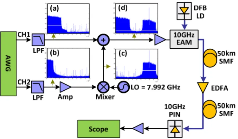
Figure 5 illustrates the experimental setup with the insets displaying the corresponding electrical spectra for an optical OFDM transmission system over up to 100-km SMF transmission. The experimental setups of 20-km, 40-km, 60-km, and 80-km SMF are similar, except that the transmission distances are different. A point-to-point transmission is adopted to emulate a long-reach OFDM-PON, since the loss of a remote node in PONs can be compensated by an optical amplifier. The baseband electrical OFDM signal is generated by an arbitrary waveform generator (AWG, Tektronix® AWG7122) using Matlab® programs. The signal processing of the OFDM transmitter consists of serial-to-parallel conversion, QAM symbol encoding, inverse fast Fourier transform (IFFT), cyclic prefix (CP) insertion, and digital-to-analog conversion (DAC). The sampling rate and DAC resolution of the AWG are 12 GS/s and 8 bits, respectively. In order to utilize the bandwidth of both passbands as shown in Figs. 3 and 4, the two-band electrical OFDM signal is composed of two streams of OFDM signals with the FFT size of 512 generated owing to the limited AWG bandwidth of only 7.5 GHz. Nevertheless, since the channel number of the AWG is only 2, the signal of the 2nd band is emulated by directly up-converting the signal from the channel 2 of the AWG, instead of independent I- and Q-channels.
With the detailed parameters of the multi-band OFDM at different transmission distances given at Table 1 at the end of this section, and to avoid similar scenario being repeated, the following paragraphs only describe the parameters of the 40-km and 100-km transmissions, because the transmission conditions of these two cases are severer than the others. That is, as shown in Fig. 4 (b), the 40-km SMF transmission has only one passband and the available bandwidth is the minimum, while the 100-km SMF transmission has the longest distance in
spite of two available passbands. Thus, these two cases could be regarded as the performance baselines of one-band and two-band OFDM signals over 20–100-km SMF transmissions.
For the case of 100-km SMF, as shown in inset (a) of Fig. 5, the channel-1 OFDM signal is located in the 1st passband, which consists of 23.44-MSym/s 64-QAM and QPSK symbols encoded at the 2nd–144th and 145th–180th subcarriers, respectively. Hence, the whole 179 subcarriers of the channel-1 signal occupy 4.195-GHz bandwidth (46.8 MHz – 4.22 GHz), yielding a total data rate of 21.78 Gbps. The channel-2 OFDM signal has the same symbol rate, but the modulation formats are 32-QAM and QPSK encoded at the 2nd–44th and 45th– 76th subcarriers, respectively, shown in inset (b) of Fig. 5. After being up-converted to 7.992 GHz (corresponding to the frequency of the 341st subcarrier), the up-converted OFDM signal occupies the 265th–339th and 343rd–417th subcarriers (6.21 GHz – 9.77 GHz) located in the 2nd passband. Therefore, the up-converted signal with 3.52-GHz bandwidth is used to emulate the signal of the 2nd band with the total data rate of 13 Gbps, shown in inset (c) of Fig. 5. As shown in inset (d) of Fig. 5, through a power coupler, both two bands are then combined to achieve a total data rate of 34.78 Gbps.
Fig. 5. Experimental setup with spectrum illustration. (a) channel 1, (b) channel 2, (c) channel 2 after up-conversion, and (d) combination of channels 1 and 2.
For the case of 40-km SMF, both the channel-1 and channel-2 OFDM signals can be only located in the 1st passband. The channle-1 OFDM signal is consisted of 23.44-MSym/s 128-QAM and 32-128-QAM symbols encoded at the 2nd–94th and 95th–135th subcarriers, respectively. Namely, these 134 subcarriers occupy 3.14-GHz bandwidth (46.8 MHz – 3.16 GHz) to yield a total data rate of 20.06 Gbps. With the same symbol rate, 64-QAM and 32-QAM formats are encoded at the 2nd–28th and 29th–51st subcarriers of the channel-2 signal, respectively, and then the signal is up-converted to 4.382 GHz, i.e. the frequency of the 187st subcarrier. Thus, by up-converting the channel-2 signal, the 136th–185th and 189th–238th subcarriers are generated at 3.19 GHz –5.58 GHz to emulate the signal of the 2nd band with a total data rate of 12.98 Gbps. After combining the signals of the both bands via a power coupler, the 33.04-Gbps OFDM signal is obtained.
Furthermore, the combined OFDM signals are then sent to the EAM to generate the optical DSB OFDM signals. After 40 km or 100 km of SMF transmission and direct-detection, the received electrical signals are both captured by a digital oscilloscope (Tektronix® DPO 71254) with a 50-GS/s sampling rate and a 3-dB bandwidth of 12.5 GHz. An off-line Matlab® DSP program is used to demodulate the OFDM signals and the demodulation process includes synchronization, FFT, one-tap equalization, and QAM symbol decoding. Lastly, from the constellation, the signal-to-noise ratio (SNR) is measured and used to calculate the bit error rate (BER).
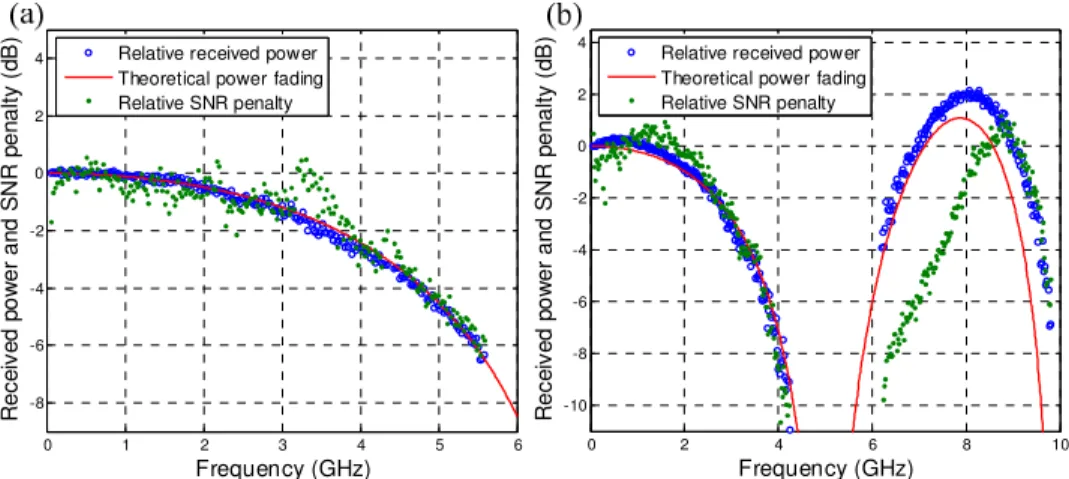
0 1 2 3 4 5 6 -8 -6 -4 -2 0 2 4 Frequency (GHz) R e c e iv e d p o w e r a n d S N R p e n a lt y ( d B )
Relative received power Theoretical power fading Relative SNR penalty 0 2 4 6 8 10 -10 -8 -6 -4 -2 0 2 4 Frequency (GHz) R e c e iv e d p o w e r a n d S N R p e n a lt y ( d B )
Relative received power Theoretical power fading Relative SNR penalty
Fig. 6. Relative received powers and SNR penalties of each subcarrier after (a) 40 km and (b) 100 km.
Fig. 7. SNR of each subcarrier and constellations of (a) 40-km and (b) 100-km SMF transmissions.
Figures 6(a) and (b) show the relative received powers of each subcarrier after 40-km and 100-km SMF, respectively. The received powers are calculated by the relative power gain of
0 1 2 3 4 5 6 14 16 18 20 22 24 26 28 Frequency (GHz) S N R ( d B ) B-to-B 40 km w/o pre-emphasis 40 km w/ pre-emphasis B-to-B 40 km
128QAM 32QAM 64QAM 32QAM
0 2 4 6 8 10 5 10 15 20 25 30 Frequency (GHz) S N R ( d B ) B-to-B 100 km w/o pre-emphasis 100 km w/ pre-emphasis 64QAM QPSK QPSK 32QAM QPSK B-to-B 100 km
(a)
(b)
Furthermore, comparing the SNRs before and after transmission without pre-emphasis in Fig. 7, the relative SNR penalties are also plotted by green dots in Fig. 6. The relative SNR penalty after 40-km transmission is consistent to the relative received power shown in Fig. 6(a), and this implies the penalty is mainly contributed by power fading. In Fig. 6(b), however, the SNR penalties of the subcarriers at 6.2–8.2 GHz are much severer than the degradation caused by power fading, compared with the other subcarriers. Actually, these additional penalties are caused by the dispersion- and chirp-relevant SSII [17]. In order to clarify the influence of SSII, the electrical spectra with and without 100-km transmission are shown in Figs. 8(a) and (b), respectively, and only the 1st passband is used to carry subcarriers to simplify the investigation of SSII. The blue curves are the measured electrical spectra, and the simulation results of green curves are also drawn for comparison. Obviously, there is unexpected power increase outside the signal band. According to the SSII theory and the small-signal approximation given in [17], a chirped OFDM signal contains Ns subcarriers with the same
power of Ps and the subcarrier spacing of ∆f at baseband, the power of the second-order SSII
at the frequency of n f∆ can be approximated as
(
)
(
)
(
)
(
(
)
)
(
)
(
(
)
)
2 2 2 s SSII s c 2 2 2 s s 2 2 2 1 8 ,1+2 cos D sinc 4 D 4 cos D sinc 2 D
n n n P P N P n n N n n N α θ θ θ θ ≅ + − × + − − − (3)
where n is a positive integer less than 2N, θD equals to
2 2
2
2π β L f∆ and Pc denotes the power
of the optical carrier. Following Eq. (3), the theoretical SSII curve is plotted by the red curve in Fig. 8(b) to prove those additional frequency components are indeed caused by the SSII. While the in-band SSII (<4.2 GHz) would have small effects on the performance of subcarriers of the 1st passband, as shown in Fig. 8(b), the stronger out-of-band SSII (4.2–8.4 GHz) could be harmful to higher-frequency bands. Figure 8 (c) shows the electrical spectrum of the OFDM signal composed of two bands after 100-km transmission. Since the subcarriers at 6.2–8.2 GHz is overlapped with the out-of-band SSII induced by the 1st band, they suffer from severer SNR penalties, as shown in both Figs. 6(b) and 7(b). Thus, the total bandwidth illustrated in Fig. 4(b) is not the only concern in a cost-effective IMDD transmission system, but the dispersion- and chirp-relevant SSII must also be considered.
0 2 4 6 8 10 -60 -50 -40 -30 -20 -10 0 Frequency (GHz) R e la ti v e P o w e r (d B ) measured SSII of 1st band 0 2 4 6 8 10 -60 -50 -40 -30 -20 -10 0 Frequency (GHz) R e la ti v e P o w e r (d B ) measured simulation SSII theory 0 2 4 6 8 10 -60 -50 -40 -30 -20 -10 0 Frequency (GHz) R e la ti v e P o w e r (d B ) measured simulation
Fig. 8. Experimental measured and simulated electrical spectra of (a) 1st band of optical B-to-B, (b) 1st band after 100-km SMF transmission and (c) 1st and 2nd bands after 100-km SMF transmission.
Furthermore, the BER performances of the EAM-based OFDM signals are plotted in Fig. 9. Over 40-km and 100-km SMF transmissions, the receiver sensitivities are −6.5 dBm and −9.5 dBm, respectively, and the transmission penalties at the FEC threshold (BER of
3
3.8 10× − ) are less than 2.8 dB and 2.5 dB, respectively. The optical power budget is crucial for designing the transmission systems of LR-PONs, and 100-km LR-PON needs the largest
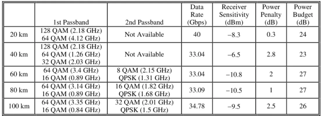
optical power budget among 20–100-km LR-PONs. The optical power following the EDFA as shown in Fig. 5 is about 16.5 dBm, thus the corresponding optical power budget of 100-km LR-PON is 26 dB, which can support the optical power loss of the following 50-km SMF and the optical splitter with 32 splitting ratio. Finally, Table 1 collates all the experimental results of 20-km, 40-km, 60-km, 80-km and 100-km SMF transmissions, including the multi-band OFDM subcarrier allocations, data rates, received power penalties, receiver sensitivities and power budgets. Both the cases of 20-km and 40-km transmissions adopt only one passband, while the others have two passbands. The minimum data rate of 33.04 Gbps is obtained after 40-km SMF, and the maximum of 40 Gbps is demonstrated after 20-km SMF. Moreover, the received power penalties and the receiver sensitivities of the 40-km and 100-km systems are worse than the others, since the available bandwidth is the minimum after 40-km SMF and the 100-km system suffers from the severest SSII.
-13 -12 -11 -10 -9 -8 -7 -6 -5 10-5 10-4 10-3 10-2 Received power (dBm) B E R 10-5 10-4 10-3 10-5 10-3 B-to-B (40 km) B-to-B (100 km) 40 km 100 km
Fig. 9. BERs of OFDM signals before and after 40-km and 100-km SMF transmissions.
Table 1. OFDM subcarrier allocations, data rates, power penalties, receiver sensitivities and power budgets of 20–100-km SMF transmissions
1st Passband 2nd Passband Data Rate (Gbps) Receiver Sensitivity (dBm) Power Penalty (dB) Power Budget (dB) 20 km 128 QAM (2.18 GHz) 64 QAM (4.12 GHz) Not Available 40 −8.3 0.3 24 40 km 128 QAM (2.18 GHz) 64 QAM (1.26 GHz) 32 QAM (2.03 GHz) Not Available 33.04 −6.5 2.8 23 60 km 64 QAM (3.4 GHz) 16 QAM (0.89 GHz) 8 QAM (2.15 GHz) QPSK (1.31 GHz) 33.04 −10.8 2 27 80 km 64 QAM (3.14 GHz) 16 QAM (0.89 GHz) 16 QAM (1.82 GHz) QPSK (1.68 GHz) 33.09 −10.5 1 27 100 km 64 QAM (3.35 GHz) 16 QAM (0.84 GHz) 32 QAM (2.01 GHz) QPSK (1.5 GHz) 34.78 −9.5 2.5 26
4. Conclusion
To summarize, this work has experimentally demonstrated optical DSB-OFDM transmission over 20–100-km SMF links using a cost-effective 10-GHz EAM and a 10-GHz PIN. Although the frequency responses of the 20–100-km EAM-based transmission systems are seriously impaired by power fading, this work efficiently and dynamically allocates different modulation levels and power levels of OFDM subcarriers in different bands to cope with uneven frequency responses and to avoid serious power fading. The experimental results show the superior performance of at least 33 Gbps over 20–100-km transmissions and the record data rate of 34.78 Gbps after 100-km SMF based on a 10-GHz EAM-based IMDD scheme.
Compared with our previous work [11], at least 57% data rate enhancement is achieved. Thus, by using the proposed multi-band OFDM subcarrier allocation scheme, the cost-effective EMLs with positive chirp parameter become available, and power fading is on longer the major bottleneck of LR-PONs. Besides, the investigation and measurement of SSII also reveal that the bandwidth limited by power fading is not the only concern; SSII must be also taken into consideration as designing the transmission system of LR-PONs. In conclusion, this experiment demonstrates a cost-effective LR-PON, which can provide more than 1-Gbps data rate to each of 32 ONUs. While 128 ONUs are required, the system could simply be upgraded by using only four wavelengths for both downstream and upstream, respectively.
Acknowledgment
The authors would like to thank the National Science Council, Republic of China, Taiwan for financially supporting this research under Contract Nos. NSC 99-2218-E-260-003- and NSC 99-2221-E-009-046-MY3.