www.rsc.org/advances
RSC Advances
This is an Accepted Manuscript, which has been through the Royal Society of Chemistry peer review process and has been accepted for publication.
Accepted Manuscripts are published online shortly after
acceptance, before technical editing, formatting and proof reading. Using this free service, authors can make their results available to the community, in citable form, before we publish the edited article. This Accepted Manuscript will be replaced by the edited, formatted and paginated article as soon as this is available.
You can find more information about Accepted Manuscripts in the
Information for Authors.
Please note that technical editing may introduce minor changes to the text and/or graphics, which may alter content. The journal’s standard Terms & Conditions and the Ethical guidelines still apply. In no event shall the Royal Society of Chemistry be held responsible for any errors or omissions in this Accepted Manuscript or any consequences arising from the use of any information it contains.
This article can be cited before page numbers have been issued, to do this please use: Y. Patil, R. Misra, M. L. Keshtov, F. Chen and G. D. Sharma, RSC Adv., 2016, DOI: 10.1039/C6RA10442H.
Symmetrical and Unsymmetrical Triphenylamine based Diketopyrrolopyrroles and their use as Donor for Solution Processed Bulk Heterojunction Organic Solar Cells
Yuvraj Patila, Rajneesh Misra*a, F. C. Chenb, M. L. Keshtovc, Ganesh D. Sharmad*
a
Department of Chemistry
Indian Institute of Technology, Indore (MP) 453552, India
b
Department of Photonics, National Chiao Tung University, 1001 University Road, Hsinchu 30010, Taiwan
c
A. N. Nesmeyanov Institute of Organoelement Compounds, Russian Academy of Sciences, Vavilova Str., 28, Moscow 119991, Russia
d
Department of Physics, The LNM Institute of Information Technology, Jamdoli, Jaipur, 303031, India
Abstract
Two small molecules DPP3 (D-π-A) and DPP4 (D-π-A-π-D) with triphenylamine (TPA) donor and diketopyrrolopyrrole (DPP) acceptor linked with ethyne linker were designed and synthesized by the Pd-catalyzed Sonogashira cross-coupling reaction. Their photonic, electronic, thermal and computational properties were investigated. The red shift in the electronic absorption spectra of DPP4 as compared to DPP3 is related to extended conjugation and increased donor-acceptor interaction. We have used DPP3 and DPP4 as
electron donor along with PC71BM as electron acceptor for the solution processed bulk
heterojunction organic solar cells. The solar cells prepared from DPP3:PC71BM and
DPP4:PC71BM (1:2) processed from chloroform (CF) exhibit a power conversion efficiency
(PCE) of 2.23% (Jsc = 6.74 mA/cm2, Voc= 0.92V and FF = 036) and 3.05% (Jsc = 8.26
mA/cm2, Voc = 0.88 V and FF = 0.42), respectively. The higher PCE of the device with DPP4
compared to DPP3 was demonstrated to the higher hole mobility and broader IPCE spectra.
The devices based on DPP3:PC71BM and DPP4:PC71BM processed with solvent additive
(1v% DIO, 1, 8-diiodooctane) showed PCE of 4.06% and 5.31%, respectively. The device optimization results from the improvement of the balanced charge transport and better nanoscale morphology induced by the solvent additive.
Keywords: Diketopyrrolopyrrole, Bulk heterojunction, Organic Solar Cells, Power
Conversion Efficiency, Solvent Additives
*Corresponding authors E-mail: [email protected] (Rajneesh Misra),
[email protected] (Ganesh D Sharma)
RSC
Advances
Accepted
Manuscript
Introduction
Bulk heterojunction (BHJ) solar cell from a blend of electron donor and electron acceptor organic semiconducting materials are potential source of renewable energy sources due to being inexpensive and lightweight with flexibility. [1] The research on the organic solar cell (OSC) materials have been currently being focused on the design and synthesis of low bandgap conjugated polymers that are capable of both light absorption and charge transport. After the optimization of bandgap and electrochemical energy levels of conjugated polymer donors, control of nanomorphology of the BHJ active layer, and interfacial layers, the power conversion efficiency (PCE) of OSCs based on these materials has exceed 10%.[2] In spite of this advancement, these materials suffer from several drawbacks, such as batch to batch variation, side length polydispersity, structural defects and difficult synthesis and purification. [3] To overcome these limitations the research is diverted to “small molecule” BHJ (SM-BHJ) solar cells, where polymer donors were replaced by the conjugated molecular systems which can be synthesized with well defined molecular architecture with desired frontier molecular orbitals to match the light harvesting of the best performing polymeric materials. [4] The PCE of SM-BHJs has been reached in the range of 9-10%. [5] The PCE of SM-BHJ solar cells could be further improved by exploring the design of new SMs that can used as donor in BHJ active layer.
The frequently used strategy to design high performance organic small molecule is to use the push-pull chromophore structure in which electron donating (D) and electron accepting (A) units are coupled together, designing semiconducting organic materials with highly conjugated backbone structure. [6] This type of small molecules exhibit low band gap, intense absorption in visible region, strong intra- and intermolecular interaction, and efficient charge transport, which is beneficial for high PCE of organic solar cells. Among the various SMs, designed for OSCs, the SMs containing diketopyrrolopyrrole (DPP), with two fused electron deficient lactam rings have been attracted lot of attention because of its unique properties such as high absorption coefficient in visible region, strong electron withdrawing property and high coplanarity facilitate intermolecular packing. DPP derivatives possess high thermal stability and used as brilliant colorants. [7] The DPP is reported as potential electron acceptor and functionalization with electron donor will results in donor-acceptor molecular system. Moreover, strong donor –acceptor (D-A) interaction between DPP core and adjacent thiophenes generate strongly hybridized frontier molecular orbitals, low lying LUMO and high lying HOMO orbitals of DPP based SMs. Therefore, most of the SMs with DPP
RSC
Advances
Accepted
Manuscript
possesses low band gap and well ordered structure in thin film and thus exhibit high Jsc in
OSCs. [8, 11] The state of art with the PCE of 7% has been reported for BHJ solar cells based on DPP SMs [9] and in the range of 6 – 9% for DPP based D–A copolymers. [10] Our group is involved in the design and synthesis of donor–acceptor molecular systems with low HOMO–LUMO gap for optoelectronic applications. [11] Ziessel et. al. have reported the symmetrical and unsymmetrical triphenylamine functionalized diketopyrrolopyrroles. [12]
In this article we wish to report the synthesis and solar cell properties of DPP3 and
DPP4 as electron donor along with PC71BM as electron acceptor in solution processed BHJ
organic solar cells. The acetylene linker between DPP and TPA is used to afford the low HOMO-LUMO gap through extended conjugation and also increase the ionization potential of resulting molecule due to relatively larger electron-withdrawing characteristics of sp
hybridization over sp2 hybridization. [13] After the optimization, we have achieved the PCE
of 4.06% and 5.31% for active layer DPP3:PC71BM and DPP4:PC71BM, respectively.
Experimental part Synthesis of DPP3
In 100 ml round bottom flask monobromodiketopyrrolopyrrole 1 (0.100 g, 0.15 mmol) and (4-ethynylphenyl) diphenylamine (0.041 g, 0.15 mmol) were dissolved in dry THF (10 ml) and triethylamine (6 ml). The reaction mixture was degassed with argon for 10 minutes and
Pd(PPh3)4 (0.0.018 g, 0.015 mmol) and CuI (0.0028 g, 0.015 mmol) were added. The
reaction mixture was stirred at 70 oC for 24 hours. After completion of reaction, the reaction
mixture was allowed to cool down to room temperature. The solvents were removed under vacuo and the product was purified by silica-column chromatography with hexane: dichloromethane (3:1) as an eluent in 75% yield.
1 H NMR (400 MHz, CDCl3, δ in ppm): 8.93 (2H, s), 7.64 (1H, s), 7.36 (3H, m), 7.28 (4H, m), 7.12 (7H, m), 7.00 (2H, d, J = 8 Hz), 4.05 (4H, s), 2.35 (1H, s), 1.74 (4H, s), 1.41 (4H, s), 1.25 (23 H, s), 0.86 (6H, s); 13C NMR (100 MHz, CDCl3, δ in ppm): 161.3, 161.2, 148.7, 146.9, 139.9, 139.1, 135.5, 135.4, 132.6, 132.5, 130.8, 129.9, 129.8, 129.5, 129.2, 128.7, 125.3, 124.0, 121.6, 114.5, 108.3, 107.9, 98.5, 81.7, 42.3, 31.9, 30.1, 30.0, 29.5, 29.31, 29.26,
26.9, 22.7, 14.1; HRMS (ESI) m/z calcd for C54H61N3O2S2 + Na: 870.4097 [M + Na]+, found
870.4094 [M + Na]+.
Synthesis of DPP4
In 100 ml round bottom flask dibromodiketopyrrolopyrrole 2 (0.100 g, 0.14 mmol) and
(4-RSC
Advances
Accepted
Manuscript
triethylamine (6 ml). The reaction mixture was degassed with argon for 10 minutes and
Pd(PPh3)4 (0.015 g, 0.014 mmol) and CuI (0.0025 g, 0.014 mmol) were then added. The
reaction mixture was stirred at 70 oC for 24 hours. After completion, the reaction mixture was
allowed to cool down to room temperature. The solvents were removed under vacuo and colored product was purified by silica-column chromatography with hexane: dichloromethane (3:1) as an eluent in 80% yield.
1
H NMR (400 MHz, CDCl3, δ in ppm): 8.93 (2H, s), 7.36 (6H, m), 7.29 (9H, m), 7.10 (11H,
m), 7.00 (4H, d, J = 8 Hz), 4.07 (4H, m), 3.13 (2H, m), 1.75 (4H, m), 1.45 (6H, m), 1.25
(21H, s), 0.85 (6H, m); 13C NMR (100 MHz, CDCl3, δ in ppm): 161.2, 148.7, 147.0, 139.0,
135.7, 132.6, 130.0, 129.7, 129.5, 129.4, 125.4, 124.0, 121.7, 114.5, 108.5, 98.7, 81.8, 46.1, 42.4, 31.9, 30.1, 29.7, 29.6, 29.31, 29.26, 26.9, 22.7, 14.2, 8.7; HRMS (ESI) m/z calcd for C74H74N4O2S2 + Na: 1137.5145 [M + Na]+, found 1137.5127 [M + Na]+.
Results and discussion
The small molecules DPP3 and DPP4 were synthesized by Pd-catalyzed Sonogashira cross-coupling reaction of mono-bromo DPP 1 and di-bromo DPP 2 with one and two equivalents of (4-ethynylphenyl) diphenylamine in 75% and 80% yield respectively (Scheme 1). The precursors mono-bromo DPP 1 and di-bromo DPP 2 were synthesized by following reported procedure. [14] The DPP3 and DPP4 were purified by repeated silica-gel column chromatography and recrystallization techniques. Both the DPPs are readily soluble in common organic solvents like dichloromethane, chloroform, toluene, tetrahydrofuran and
were well characterized by 1H NMR, 13C NMR, and HRMS techniques.
Photophysical and Thermal Properties
The electronic absorption spectra of DPP3 and DPP4 in dilute chloroform (CF) solution as well thin film cast from CF, are shown in Fig. 1 and data are listed in Table 1. Both the DPPs show absorption bands in UV-Visible region from 300 nm to 750 nm. The absorption bands at shorter (below 500 nm) and longer wavelength (510-750 nm) correspond to the π–π* transition and intramolecular charge transfer (ICT) from TPA to DPP respectively. The red shift of CT band in DPP4 as compared to DPP3 is related to the extended conjugation and increased donor-acceptor interaction. The more intense absorption for DPP4 may be due to the presence of two TPA fragments is likely to be attributed to an internal charge transfer induced by the strongly electron donating TPA unit and the π-accepting DPP unit. Moreover, both materials have shown vibrational absorption peaks in the
RSC
Advances
Accepted
Manuscript
higher wavelength region. In contrast, the absorption spectra of these DPP SMs in thin films are red shifted compared to those in solution. Such feature is attributed to a more planar conjugated backbone, further ordered structure in solid state and a higher π-electron delocalization though the molecular backbone, which could be beneficial to greater hole mobility. The optical bandgaps of these DPP3 and DPP4 were estimated from the onset edge of absorption spectra in thin film and are 1.84 and 1.72 eV, respectively.
The thermal properties of DPP3 and DPP4 were investigated by thermogravimetric analysis (TGA) under nitrogen atmosphere and curves shown in Fig. S1. The decomposition temperatures for 10% weight loss in DPP3 and DPP4 were 402 °C and 398 °C, respectively (Table 1), indicating that both DPPs are more thermally stable.
Electrochemical and Computational Properties
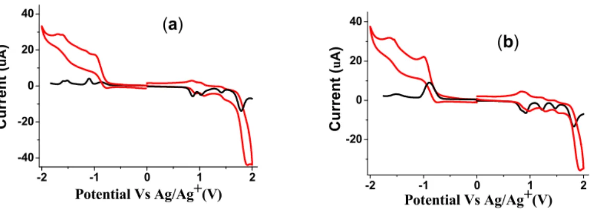
The electrochemical properties of DPPs were explored by cyclic voltammetry and differential pulse voltammetry (CV and DPV) techniques in dichloromethane solvent using
0.1 M tetrabutylammonium hexafluorophosphate (Bu4NPF6) as supporting electrolyte. The
CV and are shown in Fig. 2 and the corresponding data are listed in Table 2. Both the DPPs exhibit four oxidation waves. The first oxidation potential of DPP3 and DPP4 are almost same. The DPP3 and DPP4 show two reduction waves in CV and DPV corresponding to
formation of mono and dianion. The potentials were measured vs Ag/Ag+ as quasi reference
electrode. After each experiment, the potential of the Ag/Ag+ electrode was calibrated against
the Fc/Fc+ redox couple.
The HOMO and LUMO energy levels were estimated from the onset oxidation and reduction potentials respectively. The HOMO/LUMO energy levels are 5.12/3.69 eV and -5.07/-3.77 eV for DPP3 and DPP4, respectively. Because the exciton binding energy in an organic semiconductor is 0.3 – 0.5 eV, the LUMO offset between DPP3 or DPP4 and
PC71BM afford sufficient driving force for efficient exciton dissociation and effective
electron transfer in the active layer. The deeper HOMO energy level is desirable to achieve
the high Voc, since Voc is determined by the energy difference between the HOMO level of
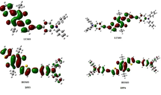
donor and LUMO energy of acceptor used in the active layer of BHJ organic solar cell. The density functional theory (DFT) calculations were carried to understand the geometry and electronic structure of DPP3 and DPP4 using the Gaussian09W program at the B3LYP/6-31+G** level. The geometry optimizations were carried out in the gas phase and frontier molecular orbitals (FMOs) are displayed in Fig. 3. The HOMO of both the DPPs are
RSC
Advances
Accepted
Manuscript
distributed on the whole molecule whereas LUMOs are localized mainly on the DPP core. The localization of LUMO on DPP core indicates the acceptor nature of DPP. This shows the typical donor–acceptor (D–A) interaction and charge transfer from TPA to DPP. [15] The theoretical band gap values obtained from DFT calculations were found to be in consistent with the electrochemical band gap values calculated from DPV and the optical band gap values from the UV-vis absorption (Table 1).
Photovoltaic properties
The solution processed BHJ solar cells based on DPP3 and DPP4 as donor along with
PC71BM as acceptor were made with a device structure ITO/PEDOT:PSS/DPP3 or
DPP4:PC71BM/ Al. The DPP3 or DPP4:PC71BM active layer was formed by spin coating of
a constant concentration of 14 mg/mL, compromising a mixture of DPP3 or DPP4 and PC71BM in CF. The photovoltaic performance of the BHJ organic solar cells are strongly
influenced by the concentration of donor and acceptor component used in the active layer, since there should be a balance between the absorption profile of active layer and charge transport within the active layer towards the final collecting electrodes. The weight ratio
between DPPs and PC71BM were varied from 1:1, 1:1.5, 1:2 and 1:2.5 in order to optimize
the ratio of donor and acceptor in active layer. The best performance was achieved for the 1:2 weight ratio for both the DPPs as donor. We have observed that the higher concentration of donor reduced the electron mobility leading the reduction of PCE, may be attributed to the poor interpenetrating pathways between the donor and acceptor. Furthermore, the concentration of DIO solvent additive was varied from 0 to 0.5%, 1% and 1.5% in order to improve the morphology of BHJ active layer. It was observed that the optimized weight ratio is 1:2 and solvent concentration is 1% of DIO in CF solution. The current–voltage (J-V)
characteristics of the optimized devices based on DPP3:PC71BM and DPP4:PC71BM active
layers cast from CF solution are shown in Fig. 4a and 4c, respectively and photovoltaic
parameters are summarized in Table 3. Under optimized DPP3:PC71BM (1:2) cast from CF
based device showed relatively high Voc of 0.92 V, but low PCE of 2.23% with a Jsc of 6.74
mA/cm2 and FF of 0.36. However, under the similar condition, the device based on
DPP4:PC71BM exhibited a PCE of 3.05% with Jsc of 8.26 mA/cm2, Voc of 0.88 V and FF of
0.42. The increase in PCE for the DPP4 based device is mainly due to the higher values of Jsc
and FF. The relatively higher Voc for DPP3 based device is proportional to its slightly deeper
HOMO energy level compared to DPP4. The higher value of Jsc for DPP4 is also confirmed
from the IPCE spectra of the devices (Fig. 4b and 4d). The IPCE spectra of devices based on
RSC
Advances
Accepted
Manuscript
DPP3 and DPP4 exhibited broad response, consistent with absorption spectra of their
corresponding active layers (Fig. 4a and 4b). It can be seen from the Fig. that absorption
spectra of the DPPs:PC71BM blends is the combination of both PC71BM and DPPs (the
absorption band corresponds around 390 nm, attributed to PC71BM whereas the absorption
band in longer wavelength region corresponds to DPPs), indicating both PC71BM and DPP
are contributing to the exciton generation and resulting photocurrent in the device. Comparing the Fig. 3b and 3d, it can be seen that DPP3 based device showed response from 350 – 660 nm with maximum IPCE value of 31% at 610 nm, whereas DPP4 based device
showed IPCE response from 350 to 690 nm with maximum value of 40% at 624 nm. The Jsc
values of DPP3 and DPP4 based devices calculated from the integration of IPCE spectra are
6.58 mA/cm2 and 8.14 mA/cm2, respectively, which are consistent with the measured values
from J-V characteristics under illumination.
We measured the J-V characteristics of hole only devices based on DPP3:PC71BM
and DPP4:PC71BM (weight ratio 1:2) active layers (as shown in Figure 5a and 5b), and
applied space charge limited current (SCLC) model to extract hole mobility (µh) using hole
only device configuration ITO/PEDOT:PSS/ active layer/Au. The estimated values of hole
mobility for DPP3 and DPP4 are 5.34 x10⁻⁶ and 7.82 x10⁻⁶ cm2/Vs, respectively (Table 3).
Moreover, we have also estimated the electron mobilities (µe) in the active layers using
similar manner employing electron only device (ITO/Al/active layer/Al), are 2.34 x 10⁻⁴
cm2/Vs and 2.42 x10⁻⁴ cm2 for DPP3 and DPP4 based active layer. This indicates that the electron to hole mobility ratio for DPP3 and DPP4 based devices is 44 and 31, respectively. Although in both devices, the electron and hole transport in unbalanced resulting lower PCE, but relatively more balanced charge transport for DPP4 based device, leading to relatively higher PCE for this device as compared to DPP3 based device.
The PCE of the devices processed with CF solution is moderate. Although the Voc is
quite respectable but the low value of PCE is mainly due to the low Jsc and FF. It is well
known that the high Jsc of the BHJ organic solar cell is related to the exciton generation and
dissociation at D-A interface and their efficient charge transport with any recombination losses during their transportation towards the electrodes and directly linked with the nanophase morphology of the BHJ active layer. The nanomorphology of the BHJ active layer can be strongly affected by the processing conditions. [16] A small amount of DIO was employed as solvent additive to improve the nanophase morphology of the active layer to improve the exciton diffusion and dissociation. The J-V characteristics of the devices based
RSC
Advances
Accepted
Manuscript
on the active layers processed with optimized DIO/CF are shown in Fig. 4a and 4c (red color) and corresponding photovoltaic parameters are summarized in Table 3. Comparing to the devices based on the active layer processed with CF, the devices processed with DIO
(1v%)/CF showed higher PCE i.e. 4.06% (Jsc = 8.88 mA/cm2, Voc = 0.88 V, and FF = 0.52)
and 5.31% (Jsc=11.16 mA/cm2, Voc=0.85 V, and FF= 0.56) for DPP3 and DPP4, respectively.
The enhancement in the PCE is attributed to the increase in both Jsc and FF. The enhancement
in Jsc with DIO additive is consistent with the IPCE spectra as shown in Fig. 3b and 3d (red
color), where the IPCE value has been increased throughout the entire wavelength region of measurement. The calculated Jsc values of devices from the IPCE spectra are 8.76 mA/cm2
and 11.08 mA/cm2, for DPP3 and DPP4 based devices respectively which are in good
agreement with measured values.
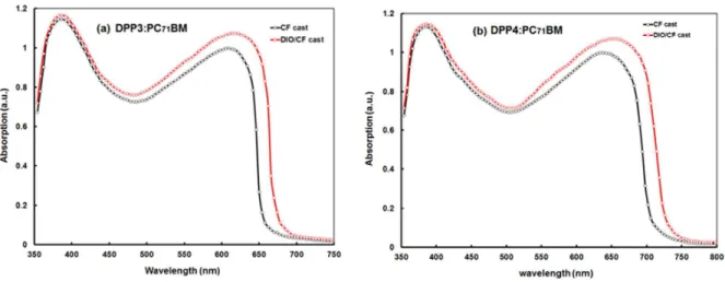
The origin of increase in the Jsc for the devices processed with DIO/CF was
investigated by absorption spectra of active layers. Fig. 5a and 6b show UV-visible optical absorption spectra of active layers processed with and without DIO additive. As compared to CF cast active layer, the DIO additive films showed a red shift, corresponding to the DPPs. This red shift is an indication of the improved ordered structure of active layer. Moreover, the absorption intensity, particularly the absorption band corresponds to DPP also increased. The broader absorption profile and increase in the absorption intensity, results more exciton generation in the active layer and may be one of the reasons for the increase in Jsc.
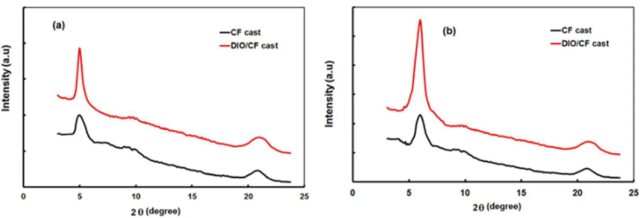
It is well known that the nanoscale morphology of BHJ active layer can be strongly affected by the solvent processing. [17] The X-ray diffraction pattern gives information about the molecular packing, crystallinity and D-A phase separation. [18] To get information about the effects of DIO additive on above parameter, XRD measurements were carried out on the
pristine films of DPP3:PC71BM and DPP4:PC71BM, spin cast from CF and DIO (1 v%)/CF
and shown in Fig. 7a and 7b. The blend film cast from CF showed weak broad scatting at 2θ = 5.53° and 5.98°, for DPP3 and DPP4, respectively, corresponding to the d-spacing of 1.34 nm and 1.18 nm, which is originated from very small crystalline domains of DPP3 and DPP4 respectively. [19] It can be seen that the diffraction peak for DPP4 is stronger than that for
DPP3, indicating more ordered stacking existed in DPP4, due to the additional TPA donor
unit, consequential improved crystallinity, which is in agreement with the absorption spectra
of DPP4. It was observed that with the addition of additive DIO in CF, the DPPs:PC71BM
blended films shows the diffraction peaks with increased diffraction intensity, indicates that the processing additive significantly enhance the crystallinity of DPP in the active layer and
RSC
Advances
Accepted
Manuscript
thus increase the degree of order. This can be interpreted that the processing additive allows the DPPs to crystallize more completely by providing increased drying time during the film formation. [20] Moreover, reduction in the d-spacing is related to the more closed packing, which is beneficial for efficient charge transport within the active layer. [21]
The transmission electron microscopy (TEM) of blended film of DPP4 and PC71BM
are shown in Fig. 8. The bright regions can be attributed to DPP4 domains, whereas the dark
regions can be attributed to PC71BM domains due to its high electron scattering density. [22]
Without DIO additive, DPP4:PC71BM films showed large phase separation of the order of 35
– 40 nm, which indicates a limited interface between DPP4 and PC71BM. However, when
1% DIO was added, the blend film morphology for DIO/CF processed film slightly changed, revealing the small phase separation in the range of 25 – 30 nm, leading the increase in the interfacing area for exciton dissociation. Similar change in the morphology was observed in
DPP3:PC71BM active layer. In general, the PC71BM component in the active layer is
selectively soluble in less volatile solvent such as DIO, therefore, addition of DIO results aggregation of the donor material during the film drying process leading to formation of more highly ordered D – A phases, leading efficient charge transport. [23]
We further investigated the effect of solvent additive on the charge transporting properties of active layers, measuring the J-V characteristics of hole only devices employing the active layers processed with DIO (1v%/CF) (Fig. 5a and 5b red color) as described earlier. The hole mobilities are compiled in Table 3. The electron mobility of the solvent additive active layers is almost same as for CF cast active layer. It was observed that the blended films cast from CF exhibited very low hole mobilities and relatively high electron mobilities. The low hole mobilities and the unbalanced electron/hole transport are the main reasons for poor performance of the devices based on the active layers without solvent
additives. Solvent additive significantly enhance the hole mobility to 4.26 x10⁻⁵ and 9.18x10⁻⁵
cm2/Vs for DPP3 and DPP4, respectively. The addition of DIO, greatly increases the hole mobility for both blended films, indicates that the enhancement in the crystallinity induced by DIO can promote the vertical percolate pathways for blended films. In addition, the electron mobility significantly improved for the active layer processed with solvent additive, and more balanced electron/hole transport (5.68 and 2.71 for DPP3 and DPP4, respectively) was achieved. The relative more balanced charge transport is in good agreement with increased FF of the devices.
The improved PCE of the devices with solvent additive processed active layers are
RSC
Advances
Accepted
Manuscript
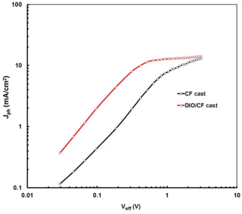
JD, where JL and JD are the current densities under illumination and in dark, respectively. Veff
= Vo-Vapp, Vo is the voltage at which Jph= 0 and Vapp is applied voltage [24]. The variation of
Jph with Veff for the devices based on DPP4:PC71BM processed with CF and DIO (1v%)/CF
are shown in Fig. 9. Similar plots have been observed for DPP3:PC71BM based devices. In
the case of device based on active layer processed with CF solvent, Jph shows stronger field
dependence across the large bias range and has not fully saturate even Veff = 3.0 V,
suggesting a significant germinate and /or bimolecular recombination and less efficient charge collection at the electrodes, thus a lower FF. However, the device processed with DIO/CF, Jph has a linearly dependence on voltage at the low value of Veff, and Jph reaches
saturation, when the effective voltage reaches to 2.4 V and 2.0 V, for DPP3:PC71BM and DPP4:PC71BM active layer, respectively. This suggest that the photogenerated excitons are
dissociated into free charge carriers and charge carriers are collected at the electrodes efficiently with reduced bimolecular recombination for the devices based on blends processed
with DIO/CF. We have estimated the maximum generation rate of free charge carriers Gmax,
according to Jphsat = qGmaxL, where q is the elementary charge and L is the active layer
thickness. The Gmax is influenced by the solvent additive with the values 0.96 x1027 m3s-1,
2.1x1027m3s-1, 1.08 x1027 m3s-1 and 3.4 x1027m3s-1 for DPP3:PC71BM (CF cast), DPP3:PC71BM (DIO/CF cast), DPP4:PC71BM (CF cast) and DPP4:PC71BM (DIOCF cast),
respectively. The trend observed for Gmax with different treatments is consistent with the
enhancement of Jsc as well as the UV-visible absorption coefficient, indicating more efficient
exciton generation and separation in the devices with DIO/CF cast. The ratio of Jph/Jsat under
short circuit conditions gives information about the overall exciton dissociation and charge collection efficiency. Under short circuit conditions, the ratios are 0.56, 0.72, 0.63 and 0.78
for DPP3:PC71BM (CF cast), DPP3:PC71BM (DIO/CF cast), DPP4:PC71BM (CF cast) and
DPP4:PC71BM (DIO/CF cast), respectively. The greater value of PC with DIO/CF processed
devices is attributed to the better phase separation in the active layer, increased hole mobility, improved balance in charge transport and enhancement in the light absorption ability.
Conclusions
In conclusion, we have synthesized unsymmetrical and symmetrical triphenylamine based diketopyrrolopyrroles (DPP3 and DPP4) by Sonogashira cross-coupling reaction and investigated their optical, thermal, electrochemical and computational properties. The red shift in the absorption spectra of DPP4 compared to DPP3 is related to extended conjugation and increased of donor-acceptor interaction. The HOMO and LUMO energy levels suggested
RSC
Advances
Accepted
Manuscript
that these DPPs can be used as electron donor along with PC71BM as electron acceptor for the
fabrication of solution processed small molecule bulk heterojunction solar cells. The solution processed BHJ small molecule processed with CF solution showed PCE of 2.23% and 3.05%
for DPP3:PC71BM and DPP4:PC71BM active layers, respectively. The higher PCE of device
based on the later active layer than that of former is attributed to the broader absorption profile of DPP4 and larger hole mobility. In an attempt to improve the PCE, we have the adopted solvent additive (SA), i.e. 1% v DIO/CF technique and achieved PCE of 4.06% and
5.31%, for DPP3:PC71BM and DPP4:PC71BM active layer, respectively. The enhancement
in the PCE with solvent additive based device is attributed to the balanced charge transport, higher light harvesting ability, and better nanoscale morphology for exciton dissociation and charge transport and collection, supported by the, XRD, TEM and mobility results. The results presented here shows that symmetrical DPP4 shows higher PCE than unsymmetrical
DPP3 and employing additional ethyne bridged triphenylamine unit results in increased
efficiency (PCE) of device from of 4.06% to 5.31%.
Supplementary data
Supporting information is available: Experimental, TGA curves, 1NMR, 13C NMR spectra
and HRMS data of compounds.
Acknowledgments
Y. P. thanks Ministry of Human Resource Development (MHRD), R. M. thanks Department of Science and Technology (Project No. EMR/2014/001257) and the Council of Scientific and Industrial Research (Project No. 01/(2795)/14/emr-II), New Delhi for the financial support. GDS is thankful to DST, Government of India (DST-RFBR Joint Research Project). F.C. Chen thanks the support by the Ministry of Science and Technology of Taiwan (grant number: MOST 103–2923-E-009-001-MY3). We are also thankful to Faculty of Physics, Lomonosov Moscow State University, 1-2 Leninskiye Gory, Moscow, 119991, Russian Federation.
References
1. (a) S. Günes, H. Neugebauer and N. S. Sariciftci, Chem. Rev., 2007, 107, 1324–1338; (b) R. Service, Solar energy Outlook brightens for plastic solar cells, Science (New York, NY) 2011, 332, 293; (c) A. J. Heeger, Adv. Mater., 2014, 26, 10-28; (d) Y.
RSC
Advances
Accepted
Manuscript
7006−7043; (e) L. Dou, Y. Liu, Z. Hong, G. Li and Y. Yang, Chem. Rev., 2015, 115 (23), 12633–12665; (f) L. Lu, T. Zheng, Q. Wu, A. M. Schneider, D. Zhao and L. Yu, Chem. Rev., 2015, 115 (23), 12666–12731.
2. (a) Y. Liu, J. Zhao, Z. Li, C. Mu, W. Ma, H. Hu, K. Jiang, H. Lin, H. Ade and H. Yan, Nat. Commun., 2014, 5, 5293; (b) Z. He, B. Xiao, F. Liu, H. Wu, Y. Yang, S. Xiao, C. Wang, T. P. Russell and Y . Cao, Nat. Photonics, 2015, 9, 174; (c) Y. Yang, W. Chen, L. Dou, W. H. Chang, H. S. Duan, B. Bob, G. Li and Y. Yang, Nat. Photonics, 2015,
9, 190; (d) J. D. Chen, C. Cui, Y. Q. Li, L. Zhou , Q.-D. Ou, C. Li, Y. Li and J.-X.
Tang, Adv. Mater., 2015, 27, 1035–1041.
3. (a) H. Feng and Y. Luping, J. Phys. Chem. Lett., 2011, 2 (24), 3102–3113; (b) O. P. Lee, A. T. Yiu, P. M. Beaujuge, C. H. Woo, T. W. Holcombe, J. E. Millstone, J. D. Douglas, M. S. Chen and J. M. J. Frechet, Adv. Mater., 2011, 23, 5359-5363; (c) B. Walker, A. B. Tamayo, X.-D. Dang, P. Zalar, J. H. Seo, A. Garcia, M. Tantiwiwat and T.-Q. Nguyen, Adv. Funct. Mater., 2009, 19, 3063-3069.
4. (a) R. C. Coffin, J. Peet, J. Rogers and G. C. Bazan, Nat. Chem., 2009, 1, 657-61; (b) Y. Z. Lin, Y. F. Li and X. W. Zhan, Chem. Soc. Rev., 2012, 41, 4245–4272; (c) M. P. Nikiforov, B. Lai, W. Chen, S. Chen, R. D. Schaller, J. Strzalka, J. Maser and S. B. Darling, Energy Environ. Sci., 2013, 6, 1513 –1520.
5. (a) A. K. K. Kyaw, D. H. Wang, D. Wynands, J. Zhang, T. Q. Nguyen, G. C. Bazan and A. J. Heeger, Nano Lett., 2013, 13, 3796-3801; (b) Y. Liu, C. C. Chen, Z. Hong, J. Gao, Y. Yang, H. Zhou, L. Dou and G. Li, Sci. Rep., 2013, 3, 3356.
6. (a) J. W. Lee, Y. S. Choi and W. H. Jo, Org. Electron., 2012, 13, 3060−3066; (b) S. Shen, P. Jiang, C. He, J. Zhang, P. Shen, Y. Zhang, Y. Yi, Z. Zhang, Z. Li and Y. Li, Chem. Mater., 2013, 25, 2274−2281; (c) M. Cheng, C. Chen, X. Yang, J. Huang, F. Zhang, B.; Xu and Li. Sun, Chem. Mater., 2015, 27, 1808−1814.
7. (a) Z. Hao and A. Iqbal, Chem. Soc. Rev., 1997, 26, 203–213; (b) O. Wallquist, in High-Performance Pigments, ed. H. M. Smith, Wiley-VCH, Weinheim 2002, 159– 184; (c) J. S. Zambounis, Z. Hao and A. Iqbal, Nature, 1997, 388, 131–132.
8. (a) S. Qu and H. Tian, Chem. Commun., 2012, 48, 3039−3051; (b) J. Liu, Y. Sun, P. Moonsin, M. Kuik, C. M. Proctor, J. Lin, B. B. Hsu, V. Promarak, A. J. Heeger and T.-Q. Nguyen, Adv. Mater., 2013, 25, 5898−5903; (c) Y. Lin, Y. Li and X. A. Zhan, Adv. Energy. Mater., 2013, 3, 724−728; (d) V. S. Gevaerts, E. M. Herzig, M. Kirkus, K. H. Hendriks, M. M. Wienk, J. Perlich, P. Müller-Buschbaum and R. A. J. Janssen, Chem. Mater., 2014, 26, 916−926; (e) L. Fu, W. Fu, P. Cheng, Z. Xie, C. Fan, M. Shi,
RSC
Advances
Accepted
Manuscript
J. Ling, J. Hou, X. Zhan and H. Chen, J. Mater. Chem. A, 2014, 2, 6589−6597; (f) W. Shin, T. Yasuda, Y. Hidaka, G. Watanabe, R. Arai, K. Nasu, T. Yamaguchi, W. Murakami, K. Makita and C. Adachi, Adv. Energy Mater., 2014, 4, 1400879- 1400888; (g) Q.-R. Yin, J.-S. Miao, Z. Wu, Z.-F. Chang, J.-L. Wang, H.-B. Wu, Y. Cao and J. Mater. Chem. A, 2015, 3, 11575−11586; (h) Y. Lin, L. Ma, Y. Li, Y. Liu, D. Zhu and X. Zhan, Adv. Energy Mater., 2013, 3, 1166−1170.
9. (a) J.-L. Wang, Z. Wu, J.-S. Miao, K.-K. Liu, Z.-F. Chang, R.-B. Zhang, H.-B. Wu and Y. Cao, Chem. Mater., 2015, 27, 4338−4348; (b) H. Qin, L. Li, F. Guo, S. Su, J. Peng, Y. Cao and X. Peng, Energy Environ. Sci., 2014, 7, 1397–1401.
10. (a) J. W. Jung, F. Liu, T. P. Russell and W. H. Jo, Energy Environ. Sci., 2012, 5, 6857–6861; (b) H. Choi, S.-J. Ko, T. Kim, P.-O. Morin, B. Walker, B. H. Lee, M. Leclerc, J. Y. Kim and A. J. Heeger, Adv. Mater., 2015, 27, 3318–3324.
11. (a) Y. Patil, T. Jadhav, B. Dhokale and R. Misra, Asian J. Org. Chem., 2016, DOI: 10.1002/ajoc.201600194; (b) Y. Patil, R. Misra, A. Sharma and G. D. Sharma, Phys. Chem. Chem. Phys., 2016, 18, 16950-16957; (c) B. Dhokale, T. Jadhav, S. M. Mobin, and R. Misra, RSC Adv., 2015, 5, 57692–57699; (d) T. Jadhav, R. Maragani, R. Misra, V. Sreeramulu, D. N. Rao and S. M. Mobin, Dalton Trans., 2013, 42, 4340–4342; (e) R. Misra, P. Gautam, T. Jadhav and S. M. Mobin, J. Org. Chem., 2013, 78, 4940– 4948.
12. (a) T. Roland, E. Heyer, L. Liu, A.Ruff, S. Ludwigs, R. Ziessel, and S. Haacke, J. Phys. Chem. C, 2014, 118 (42), 24290–24301; (b) E. Heyer and R. Ziessel, J. Org. Chem., 2015, 80 (13), 6737–6753.
13. M. Seri, A. Marrocchi, D. Bagnis, R. Ponce, A. Taticchi, T. J. Marks and A. Facchetti, Adv. Mater., 2011, 23, 3827-3831.
14. C. H. Woo, P. M. Beaujuge, T. W. Holcombe, O. P. Lee and J. M. J. Frechet, J. Am. Chem. Soc., 2010, 132, 15547–15549.
15. Y. Patil, T. Jadhav, B. Dhokale and R. Misra, Eur. J. Org. Chem., 2016, 4, 733–738; (b) Y. Patil, R. Misra, M. L. Keshtov and G. D. Sharma, J. Phys. Chem. C, 2016, 120, 6324−6335.
16. (a) Y. Sun, G. C. Welch, W. L. Leong, C. J. Takacs, G. C. Bazan and A. J. Heeger, Nat. Mater., 2012, 11, 44–48; (b) J. K. Lee, W. L. Ma, C. J. Brabec, J. Yuen, J. S. Moon, J. Y. Kim, K. Lee, G. C. Bazan and A. J. Heeger, J. Am. Chem. Soc., 2008,
130, 3619–3623.
RSC
Advances
Accepted
Manuscript
17. Y. Huang, W. Wen, S. Mukherjee, H. Ade, E. J. Kramer and G. C. Bazan, Adv. Mater., 2014, 26, 4168–4172.
18. (a) S.-S. Cheng, P.-Y. Huang, M. Ramesh, H.-C. Chang, L.-M. Chen, M. Yeh, C.-L. Fung, M.-C. Wu, C.-C. Liu, C. Kim, H.-C. Lin, M.-C. Chen and C.-W. Chu, Adv. Funct. Mater., 2014, 24, 2057–2063; (b) A. K. K. Kyaw, D. H. Wang, C. Luo, Y. Cao, T. Q. Nguyen, G. C. Bazan and A. J. Heeger, Adv. Energy Mater., 2014, 4, 1301469.
19. (a) J. Huang, C. Zhan, X. Zhang, Y. Zhao, Z. Lu, H. Jia, B. Jiang, J. Ye, S. Zhang and A. Tang, ACS Appl. Mater. Interfaces, 2013, 5, 2033–2039; (b) S. Zhang, B. Jiang, C. Zhan, J. Huang, X. Zhang, H. Jia, A. Tang, L. Chen and J. Yao, Chem. Asian J., 2013,
8, 2407 – 2416.
20. J. Peet, N. S. Cho, S. K. Lee and G. C. Bazan, Macromolecules, 2008, 41, 8655–8659. 21. H. X. Zhou, L. Q. Yang and W. You, Macromolecules, 2012, 45, 607–632.
22. X. N. Yang, J. Loos, S. C. Veenstra, W. J. H. Verhees, M. M. Wienk, J. M. Kroon, M. A. J. Michels and R. A. J. Janssen, Nano Lett., 2005, 5, 579 –583.
23. (a) A. K. K. Kyaw, D. H. Wang, V. Gupta, W. L. Leong, L. Ke, G. C. Bazan and A. J. Heeger, ACS Nano., 2013, 7, 4569–4577; (b) D. H. Wang, A. K. K. Kyaw, J.-R. Pouliot, M. Leclerc and A. J. Heeger, Adv. Energy Mater., 2014, 4, 1300835; (c) B. Chen, Y. Yang, P. Cheng, X. Chen, X. Zhan and J. Qin, J. Mater. Chem. A, 2015, 3, 6894- 6900.
24. (a) C. M. Proctor, M. Kuik and T. Q. Nguyen, Prog. Polym. Sci., 2013, 38, 1941-1960; (b) P. W. M. Blom, V. D. Mihailetchi, L. J. A. Koster and D. E. Markov, Adv. Mater., 2007, 19, 1551–1566.
Table 1 Photophysical, electrochemical, thermal and computational properties of DPP3 and DPP4.
a
in dilute CF solution, bthin film cast from CF solution, cEgopt =1240/
λ
onset, λonset is onsetabsorption edge is absorption spectra in thin film, destimated from electrochemical analysis,
λmax (nm) ε/104 (M-1.cm-1) a λmax (nm)b ) (eV Egopt c E g elect. (eV)d Eg DFT (eV)e Te (°C)f DPP3 583 (2.3), 551(2.8) 618 1.84 1.43 2.24 402 DPP4 627(3.3), 587(2.3) 658 1.72 1.30 2.07 398
RSC
Advances
Accepted
Manuscript
d
estimated from electrochemical analysis, eestimated from DFT calculation, festimated from
TGA.
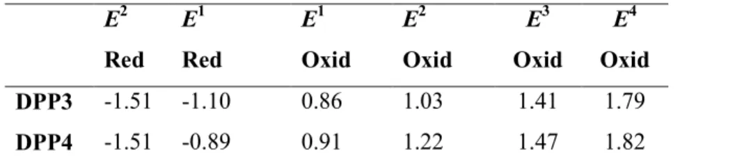
Table 2 Electrochemical properties of DPP3 and DPP4a.
E2 Red E1 Red E1 Oxid E2 Oxid E3 Oxid E4 Oxid DPP3 -1.51 -1.10 0.86 1.03 1.41 1.79 DPP4 -1.51 -0.89 0.91 1.22 1.47 1.82 a
The electrochemical analysis was performed in a 0.1 M solution of Bu4NPF6 in
dichloromethane at 100 mVs−1 scan rate, versus Ag/Ag+ at 25 °C.
Table 3 Photovoltaic parameters for the BHJ organic solar cells using optimized DPP3:PC71BM and DPP4:PC71BM active layer under different processing conditions.
Active layer Jsc (mA/cm2) Voc (V) FF PCE (%) µh (cm2/Vs) µe/µh DPP3:PC71BMa 6.74 0.92 0.36 2.23 (2.18)c 5.34x10⁻⁶ 44 DPP4:PC71BMa 8.26 0.88 0.42 3.05 (2.98)c 7.82x10⁻⁶ 31 DPP3:PC71BMb 8.88 0.88 0.52 4.06 (3.97)c 4.26x10⁻⁵ 5.68 DPP4:PC71BMb 11.16 0.85 0.56 5.31(5.24)c 9.18x10⁻⁵ 2.71 aCF cast b DIO/CF c average to 8 devices
RSC
Advances
Accepted
Manuscript
Scheme 1 Synthesis of triphenylamine based DPP3 and DPP4.
Fig. 1 Electronic absorption spectra of DPP3 and DPP4 in CF solution (10-4 M) and thin films cast from CF.
-2 -1 0 1 2 -40 -20 0 20 40 C u rr e n t ( u A ) Potential Vs Ag/Ag+(V) (a) -2 -1 0 1 2 -20 0 20 40 C u rr e n t ( u A ) Potential Vs Ag/Ag+(V) (b)
Fig. 2 cyclic voltammetry (CV) (red line) and differential pulse voltammetry (DPV) (black
line) plots of (a) DPP3 (b) and DPP4.
RSC
Advances
Accepted
Manuscript
Fig. 3 The frontier molecular orbitals of DPP3 and DPP4 estimated by DFT calculations.
Fig. 4 Current –voltage (J-V) characteristics under illumination (AM15.G, 100 mW/cm2) (a,
c) and IPCE spectra (b, d) for the BHJ organic solar cells based on optimized DPP3:PC71BM
and DPP4:PC BM active layers cast from CF and DIO (3v%)/CF solutions.
RSC
Advances
Accepted
Manuscript
Fig. 5 Current –voltage (J-V) characteristics of the hole only devices based on (a) DPP3:PC71BM and (b) DPP4:PC71BM active layers processed with CF and DIO (3v%)/CF
solutions. The solid lines represent the SCLC fitting.
Fig. 6 Normalized absorption spectra of (a) DPP3:PC71BM and (b) DPP4:PC71BM thin films
processed with and without DIO solvent additives.
RSC
Advances
Accepted
Manuscript
Fig. 7 XRD patterns of (a) DPP3:PC71BM and (b) DPP4:PC71BM thin films cast from CF
and DIO/CF solutions.
Fig. 8 TEM images of DPP4:PC71BM (1:2) films processed with CF and DIO/CF solution.
The scale bar is 100 nm.
RSC
Advances
Accepted
Manuscript
Fig. 9 Variation of Photocurrent density (Jph) with effective voltage (Veff) for devices based
on DPP4:PC71BM processed with CF and DIO/CF solvents under constant incident light
intensity.