Efficient green organic light-emitting diodes with stericly hindered coumarin dopants
Chin H. Chen and Ching W. Tang
Citation: Applied Physics Letters 79, 3711 (2001); doi: 10.1063/1.1420583 View online: http://dx.doi.org/10.1063/1.1420583
View Table of Contents: http://scitation.aip.org/content/aip/journal/apl/79/22?ver=pdfcov
Published by the AIP Publishing
Articles you may be interested in
High-brightness, high-color-purity, white organic light-emitting diodes featuring multiple emission layers
J. Appl. Phys. 105, 064318 (2009); 10.1063/1.3097285
Efficient white-light-emitting diodes based on polymer codoped with two phosphorescent dyes
Appl. Phys. Lett. 87, 193502 (2005); 10.1063/1.2119407
White organic light-emitting diode comprising of blue fluorescence and red phosphorescence
Appl. Phys. Lett. 86, 113507 (2005); 10.1063/1.1879108
High-performance polymer light-emitting diodes doped with a red phosphorescent iridium complex
Appl. Phys. Lett. 80, 2308 (2002); 10.1063/1.1462862
Efficient light-emitting diodes based on a binaphthalene-containing polymer
Appl. Phys. Lett. 75, 3745 (1999); 10.1063/1.125442
This article is copyrighted as indicated in the article. Reuse of AIP content is subject to the terms at: http://scitation.aip.org/termsconditions. Downloaded to IP: 140.113.38.11 On: Thu, 01 May 2014 07:03:18
Efficient green organic light-emitting diodes with stericly hindered
coumarin dopants
Chin H. Chena)
Microelectronics and Information Systems Research Center, Department of Applied Chemistry, National Chiao Tung University, Hsinchu, Taiwan 30050, Republic of China
Ching W. Tang
Display Technology Laboratory, Eastman Kodak Company, Rochester, New York 14650 共Received 29 May 2001; accepted for publication 1 October 2001兲
We have discovered two stericly hindered green coumarin derivatives which showed signi-ficantly better thermal stability and overall electroluminescence 共EL兲 performance than those of the corresponding 3-共2-benzothiazolyl兲-7-共diethylamino兲-2H-1-benzopyran-2-one 共C-6兲 and 10-共2-benzothiazolyl兲-1,1,7,7-tetramethyl- 2, 3, 6, 7-tetrahydro-1H,5H,11H-benzo关l兴pyrano关6,7, 8-i j ] quinolizin-11-one 共C-545T兲. The strategic incorporation of bulky spacer t-butyl groups in these dopants considerably delays the onset of concentration quenching. In particular, 10- 关2-(5, 7-di-t-butyl)benzothiazolyl ]-1, 1, 7, 7- tetramethyl- 2, 3, 6, 7- tetrahydro-1H,
5H,11H-benzo-关l兴pyrano关6,7,8-i j兴 quinolizin-11-one 共C-545TB兲 with its superb thermal stability (Tg⫽142 °C;
Td⫽327 °C), high luminance efficiency 共⬃13 cd/A兲, good Commission Interationale d’Eclairage
共CIE兲 coordinates 共x⫽0.30; y⫽0.64兲 and a nearly flat EL efficiency dependence on drive current
stands out as one of the best choice of green dopants for use in the passive-matrix organic light-emitting diode displays. © 2001 American Institute of Physics. 关DOI: 10.1063/1.1420583兴
Since the discovery of the multilayered organic light-emitting diodes共OLED兲 by Tang and co-workers at Kodak,1 phenomenal progress in the areas of materials and devices have been made by many research groups throughout the world.2 Due to its low power consumption, high efficiency, wide viewing angle, fast response time, and compact and lightweight nature of the device, the OLED has rapidly be-come one of the major flat-panel display technologies in the new century.3–5One of the key developments in the advance-ment of this emissive display technology can be attributed to the discovery of the guest-host doped emitter system.6This is because a single host with optimized transport and lumi-nescent properties may be used together with a variety of highly fluorescent guest dopants leading to electrolumines-cence 共EL兲 of desirable hues with high efficiencies. This doping principle has recently been extended to the exploita-tion of highly phosphorescent materials leading to nearly 100% internal EL efficiency.7 Another advantage of the doped emitter system in OLED is the enhancement of its operational stability by transferring the electrically generated exciton to the highly emissive and stable dopant site thus minimizing its possibility for nonradiative decay.8
One of the earliest dopants used in OLED to generate efficient EL emission in the green was 3- 共2-benzothiazolyl兲-7-共diethylamino兲-2H-1-benzopyran-2-one, known as C-6
共Ref. 9兲, which fluoresces at max 505 nm 共EtOH兲 with
78% photoluminescence 共PL兲 quantum yield.10 Subse-quently, it was discovered that by rigidizing the donor moiety
关Et2N-兴 via cyclization to form the julolidine ring
as in 10-
共2-benzothiazolyl兲-2,3,6,7-tetrahydro-1H,5H,11H-benzo-关l兴pyrano关6,7,8-i j兴quinolizin-11-one 共C-545兲 共Fig. 1兲, a more fluorescent dye (PL⬃90%) with better color could be realized by virtue of its structural coplanarity which aligns the p-orbital of nitrogen to overlap with the-orbitals of the phenyl ring for more effective conjugation.11The enhance-ment of quantum efficiency is believed to be derived from diminishing the nonradiative deactivation of the excited state by reducing the internal mobility inherent in the 关Et2N-兴
moiety of C-6. The other advantage of C-545 entails the fact
a兲Author to whom all correspondence should be addressed: electronic mail:
[email protected] FIG. 1. EL device configuration and molecular structures of dopants.
APPLIED PHYSICS LETTERS VOLUME 79, NUMBER 22 26 NOVEMBER 2001
3711
0003-6951/2001/79(22)/3711/3/$18.00 © 2001 American Institute of Physics
This article is copyrighted as indicated in the article. Reuse of AIP content is subject to the terms at: http://scitation.aip.org/termsconditions. Downloaded to IP: 140.113.38.11 On: Thu, 01 May 2014 07:03:18
that its emission, now about 15 nm redshifted 共to 519 nm兲 from that of C-6, is closer to the peak of eye sensitivity near 550 nm. Therefore, it is more suitable for display application for the ‘‘green’’ emitter.
The disadvantage of C-545, however, is that due to its nearly planar structure, it also has a greater tendency to ag-gregate in the solid state. In studies of both PL and EL of C-545 doped tris共8-hydroxyquinolinato兲aluminum (AlQ3) at
a concentration ⬎1%, a shoulder at the long-wavelength edge of the emission spectrum begins to grow which ulti-mately results in an undesirable hue shift and lowering of its luminance efficiency.12 Further modification of the julolidyl ring in C-545 by introducing four strategically positioned methyl groups as steric spacers to minimize the dye–dye interaction at high dopant concentration led to the dis-covery of 10- 共2-benzothiazolyl兲-1,1,7,7-tetramethyl-2,3,6,7-tetrahydro- 1H,5H,11H- benzo关l兴pyrano关6,7,8-i j兴quinolizin -11-one 共C-545T兲.13 The combined advantages of high luminance efficiency, nearly perfect hue, and its resistance to concentration quenching makes C-545T an ideal candidate for doped green emitter of choice in various OLED display applications. Other notable green dopants that have been reported are quinacridone,14 dimethylquinacridone,15 and electrophosphorescent fac tris共2-phenylpyridine兲iridium
关Ir共ppy兲3兴.16
However, these coumarin derivatives usually have rela-tively low glass transition temperature (Tg) which will
im-pact on the thermal stability of the devices. Furthermore, in EL applications, there is always the need to modify the dop-ant structure to enhance the EL efficiency in the devices to save power consumption. This is particularly important for the passive-matrix displays where the system would need to be capable of very high luminance at low voltage and have a ‘‘flat’’ cd/A response with respect to drive voltage. Specific substituents therefore are needed to increase the thermal sta-bility and to enhance the EL efficiency of a given green emitting EL device based on coumarin/AlQ3emitter without
significantly affecting the color of the emission.
We report in this letter, on the green dopants C-6DB and C-545TB which have all the desired attributes mentioned.17 The device architectures in which to compare the EL perfor-mances of C-6DB vs C-6 and C-545TB vs C-545T along with their chemical structures are given in Fig. 1.
In the organic EL test structure, the emitting layer was AlQ3 plus v% of dopant 共37.5 nm兲, the hole
trans-port layer was N,N
⬘
-bis(1-naphthyl)-N,N⬘
-diphenyl-1,1⬘
-biphenyl-4,4⬘
diamine共NPB兲 共75 nm兲 and 37.5 nm of AlQ3was evaporated as the backing electron transport layer. An additional anode modification layer which serves to lower the barrier of hole injection was inserted between the NPB layer and the indium-tin-oxide 共ITO兲 electrode. The latter was typically 100 nm thick with a sheet resistance of about
16 ohm/sq. Prior to the organic deposition, the ITO coated glass plate was thoroughly cleaned by scrubbing, sonication, vapor degreasing, and oxygen plasma treatment. In this work, we used two different hole injection materials in our experiments to demonstrate the advantage of dopants of C-6DB and C-545TB. In device A, 15 nm of copper phtha-locyanine共CuPc兲 was used while in device B, CHF3plasma
was used instead to modify the ITO surface.18
All EL devices were fabricated according to a protocol previously established at Kodak.19The active area of the EL device, defined by the overlap of the ITO and the cathode electrodes, was 0.1 cm2. The EL device was completed with encapsulation in a dry argon glove box. The EL emission spectra and current–voltage–luminance characteristics of the devices were measured with a diode array rapid scan system using a Photo Research PR650 spectrophotometer and a computer-controlled dc source.
The thermal properties of these dopants were evaluated by differential scanning calorimetry and thermogravimetric analysis at a heating rate of 10 °C/min under nitrogen and are compared in Table I. Both dopants have higher glass transi-tion (Tg) and onset decomposition temperatures (Td) than
the corresponding C-6 and C-545T. In particular, C-545TB has a Tg of 142 °C which is 42 °C higher than that of
C-545T. A higher Tg is desirable for a choice of dopant
ma-terials as it will impart better operational stability to the de-vice. Likewise, a higher Td will also prevent dopants from
thermal decomposition during resistively heated vacuum deposition.
The EL performances of device A and device B under a selected set of optimal doping concentrations of C-6 vs C-6DB and C-545T vs C-545TB are compared, respectively, in Table II. To ensure the validity of these comparisons, nearly identical coating conditions were strictly followed be-tween each set of doping experiments. The EL cells after encapsulation in the dry box were driven with a current den-sity of 20 mA/cm2. In general, the CHF3plasma treated ITO which has better hole injection characteristics has a lower drive voltage than that of CuPc. In both type of devices, the di-共t-butyl兲-substituted dopants, C-6DB and C-545TB, pro-duced more light under the similar drive conditions than C-6 and C-545T. This is reflected in the advantage of the lumi-nance efficiency gain of 1.2–1.4 cd/A in device A and 2.4 – 2.7 cd/A in device B. In power consideration, the gains are
TABLE I. Comparison of thermal properties.
Dopant Tg共°C兲 Tm共°C兲 Td共°C兲
C-6 ¯ 209 317
C-6DB 107 286 348
C-545T 100 230 318
C-545TB 142 276 327
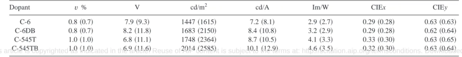
TABLE II. Comparison of EL performances of device A and B shown in parenthesis driven at 20 mA/cm2.
Dopant v % V cd/m2 cd/A Im/W CIEx CIEy
C-6 0.8共0.7兲 7.9共9.3兲 1447共1615兲 7.2共8.1兲 2.9共2.7兲 0.29共0.28兲 0.63共0.63兲
C-6DB 0.8共0.7兲 8.2共11.8兲 1683共2150兲 8.4共10.8兲 3.2共2.9兲 0.29共0.28兲 0.62共0.64兲
C-545T 1.0共1.0兲 6.8共11.1兲 1748共2364兲 8.7共10.5兲 4.1共3.3兲 0.33共0.30兲 0.63共0.65兲
C-545TB 1.0共1.0兲 6.9共11.6兲 2014共2585兲 10.1共12.9兲 4.6共3.5兲 0.32共0.30兲 0.63共0.64兲
3712 Appl. Phys. Lett., Vol. 79, No. 22, 26 November 2001 C. H. Chen and C. W. Tang
This article is copyrighted as indicated in the article. Reuse of AIP content is subject to the terms at: http://scitation.aip.org/termsconditions. Downloaded to IP: 140.113.38.11 On: Thu, 01 May 2014 07:03:18
also significant with 0.3–0.5 lm/W in device A and 0.2 lm/W in device B. Another attractive attribute of these dopants is the fact that these gains in luminance do not significantly change their 1931 Commission Internationale d’Eclairage
共CIE兲 coordinates as exemplified in Table II. From these
data, it is concluded that dopant C-545TB offers the best overall luminance efficiency, power efficiency, and the most saturated green with CIE x⫽0.32; y⫽0.63 in device A and CIE x⫽0.30; y⫽0.64 in device B as a doped emitter in AlQ3
for OLED display applications.
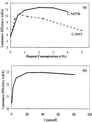
The doping concentration in AlQ3 and luminance
effi-ciency dependency curves for C-545T and C-545TB in de-vice A are compared in Fig. 2共a兲. Dopant C-545TB with extra steric spacers is apparently less sensitive to concentra-tion quenching than C-545T. The luminance efficiency of C-545T begins to drop after 1% while the di- 共t-butyl兲-substituted C-545TB derivative remains robust over a wide range of doping concentration between 1– 4%. Using CuPc
共15 nm兲 as the injection layer, the turn-on voltage of
C-545TB doped emitter is about 6.6 V and at 17.5 V, the luminance is well over 10 000 cd/m2.
An additional advantage of C-545TB can be found in Fig. 2共b兲 from its nearly flat response of luminance effi-ciency 共cd/A兲 with respect to a wide range of drive current conditions from 20 to 80 mA/cm2at an optimal doping con-centration of about 1%. This is particularly desirable for the
passive-matrix displays where the system would need to be capable of very high luminance at low voltage and have a flat cd/A response with respect to drive voltage.
In conclusion, we report on two stericly hindered green dopants, C-6DB and C-545TB, which showed significantly better thermal stability as well as overall EL performance than those of the corresponding C-6 and C-545T. In particu-lar, dopant C-545TB with its superb thermal stability, high luminance efficiency, good colorimetry, and a nearly flat EL efficiency dependence on drive current stands out as an out-standing choice of green dopants for use in the passive-matrix OLED displays.
This work is supported in part by Grants from the Na-tional Sciences Council of the Republic of China for one of the authors 共C.H.C.兲. The authors also gratefully acknowl-edge the assistance of D. L. Comfort and L. Nguyen for the fabrication of EL devices at the Display Technology Labora-tory of Kodak, Rochester, New York.
1
C. W. Tang and S. A. Van Slyke, Appl. Phys. Lett. 51, 913共1987兲.
2For recent reviews, see: C. H. Chen, J. Shi, and C. W. Tang, Macromol.
Symp. 125, 1共1997兲.
3H. Nakada and T. Tohma, Display Devices ’98 , 29共1998兲. 4
S. Miyaguchi, S. Ishizuka, T. Wakimoto, J. Funaki, Y. Fukuda, H. Kubota, K. Yoshida, T. Watanabe, H. Ochi, T. Sakamoto, M. Tsuchida, I. Ohshita, and T. Tohma, J. SID 7Õ3, 221 共1999兲.
5G. Rajeswaran, M. Itoh, M. Boroson, S. Barry, T. K. Hatwar, K. B. Kahen,
K. Yoneda, R. Yokoyama, T. Yamada, N. Komiya, H. Kanno, and H. Takahashi, SID ’00 Digest, 40, 1共2000兲.
6C. W. Tang, S. A. Van Slyke, and C. H. Chen, J. Appl. Phys. 65, 3610 共1989兲.
7M. A. Baldo, M. E. Thompson, and S. R. Forrest, Nature共London兲 403,
750共2000兲.
8
C. W. Tang, 1996 SID International Sym. Digest of Technical Papers 共SID, Santa Ana, CA兲, p. 181; J. Shi and C. W. Tang, Appl. Phys. Lett. 70, 1665共1997兲.
9K. H. Drexhage, Dye Lasers, edited by F. P. Schafer ‘‘Topics in Applied
Physics,’’ Vol. 1, Springer, Berlin, 1973, p. 144; Laser Dyes, edited by M. Maeda共OHM, Tokyo, 1984兲.
10G. A. Reynolds and K. H. Drexhage, Opt. Commun. 13, 222共1975兲. 11A. N. Fletcher, D. E. Bliss, and J. M. Kauffman, Opt. Commun. 47, 57
共1983兲. 12
T. Wakimoto and Y. Yonemoto, Japan Patent No. 6,240,243共1994兲.
13J. L. Fox and C. H. Chen, US Patent No. 4,736,032共1988兲; T. Inoe and K.
Nakatani, Japan Patent No. 6,009,952 共1994兲; J. Ito, Japan Patent No. 7,166,160共1995兲.
14
T. Wakimoto, R. Murayama, K. Nagayama, Y. Okuda, and H. Nakada, Appl. Surf. Sci. 113, 698共1997兲.
15J. Shi and C. W. Tang, Appl. Phys. Lett. 70, 1665共1997兲.
16M. A. Baldo, S. Lamansky, P. E. Burrows, M. E. Thompson, and S. R.
Forrest, Appl. Phys. Lett. 75, 4共1999兲; T. Tsutsui, M.-J. Yang, M. Yahiro, K. Nakamura, T. Watanabe, T. Tsuji, Y. Fukuda, T. Wakimoto, and S. Miyaguchi, Jpn. J. Appl. Phys., Part 2 38, L1502共1999兲.
17For materials synthesis, see: C. H. Chen, C. W. Tang, J. Shi and K. P.
Klubek, US Patent No. 6,020,078共2000兲.
18
L. S. Hung, L. R. Zheng, and M. G. Mason, Appl. Phys. Lett. 78, 673 共2001兲.
19S. A. Van Slyke, C. H. Chen, and C. W. Tang, Appl. Phys. Lett. 69, 2160 共1996兲.
FIG. 2. 共a兲 Luminance efficiency vs doping concentration of C-545T and C-545TB and共b兲 luminance efficiency of C-545TB vs current density.
3713 Appl. Phys. Lett., Vol. 79, No. 22, 26 November 2001 C. H. Chen and C. W. Tang
This article is copyrighted as indicated in the article. Reuse of AIP content is subject to the terms at: http://scitation.aip.org/termsconditions. Downloaded to IP: 140.113.38.11 On: Thu, 01 May 2014 07:03:18