Integrated System Architecture Synthesis of Distributed Embedded Systems for Multimedia Applications
6
0
0
全文
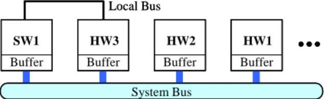
(2) the data from/to communication link. For the buffering model, the out-going data can be transferred in the later time after finishing computation and the incoming data can be held before computation. Therefore, the scheduling will be more flexible and the communication will not affect the computation of PEs. An example of target architecture, which consists of four PEs, one system bus, and one local bus between SW1 and HW3, is shown in Fig. 1. Local Bus SW1. HW3. HW2. HW1. Buffer. Buffer. Buffer. Buffer. time. Stage 1 HW1 F1 HW3 F3 SW1 F2. System Bus. Figure 1: An example of target architecture. 2.2: TASK GRAPH Typically multimedia applications are dominated by dataflow constructs and can be described as a task graph at a coarse level of granularity. A task graph G(V, E, I, O) is a directed acyclic graph, where V denotes a set of functional nodes and E denotes a set of communication edges. Moreover, I and O are dummy nodes called the input and output nodes which are used to model the I/O environment and specify the throughput constraint. Fi ∈ V is a functional node and Cn(Fi1, Fi2) ∈ E is a communication edge from source functional node Fi1 to destination functional node Fi2. For the dependency relation in G, the functional node should be activated after all its input edges are finished. And the output edges cannot be activated until the source functional node is finished. The loop-carried dependency is denoted by a dotted edge with dependence distance. The dotted edge Cn(Fi1, Fi2) with dependence distance Dn implies that the data produced by Fi1 in the mth iteration is consumed by Fi2 in the m+Dn iteration. Considering the task graph depicted in Fig. 2, C2 and C3 can be activated after F1 is finished, and F4 cannot be activated until both C4 and C5 are finished. Moreover, D7 = 1 indicates that the data produced by F3 in the mth iteration is consumed by F1 in the m+1 iteration. C2 I. C1. F1 C3. F2 C7 D7 = 1 F3. C4 F4. C6. which it processes input samples, and this is usually the prime constraint on most multimedia applications. In the proposed approach, pipelined scheduling is useful to design the system architecture with less area and/or power consumption under throughput constraint. The throughput constraint ℑ specifies the difference in the arrival time of two consecutive input samples. We also refer to this time as the pipeline stage delay, since this would be the required delay of a pipeline stage in the design. Fig. 3 depicts a two-stage pipelined schedule of the task graph shown in Fig. 2 under throughput constraint ℑ = 120.. O. C5. Figure 2: An example of task graph. 2.3: PIPELINED SCHEDULING In the iterative nature of multimedia applications, pipelined scheduling benefits the performance if there are enough resources. Pipelining divides the system into concurrently executing stages, thus increasing its data rate. The throughput of a multimedia system is the rate at. C1 System Bus Local C 3 Bus. C2 C7. Stage 2. F1 F3 F4 C1. C5. F1 F3 F4. F2 C2C7 C6. C1. F2 C2 C7 C6. C5 C3. 120. Steady state. Steady state. C5 C3. 120. 120. Figure 3: An example of pipelined scheduling. 2.4: COMMUNICATION SYNTHESIS The communication topology has significantly impact on the performance and power consumption of system architecture. There are three communication types for each Cn(Fi1, Fi2) ∈ E in our target architecture. First, if Fi1 and Fi2 are executed on the same PE, the communication data don’t be transferred through bus leading to no extra communication time and power. For example, C4(F2, F4) don’t be shown in Fig. 2 because F2 and F4 are mapped onto the same PE (SW1). Second, communication data is transferred through a private local bus. The local bus will increase the area of target architecture, but better performance or lower power consumption can be achieved. For example, C3(F1, F3) in Fig. 3 is performed on a private local bus. Third, communication data is transferred through the shared system bus. The pipeline scheduler must avoid the communication collision on the shared system bus.. 2.5: DYNAMIC VOLTAGE SCALING DVS dynamically scales the supply voltage and operational frequency of system’s PEs in accordance with the performance requirements of the applications to reduce power consumption. DVS are highly inter-dependent with mapping, pipelined scheduling, and communication synthesis. For example, pipelined scheduling cannot be performed without the execution time of computation tasks, which are available only after PEs and supply voltages are selected. In the target architecture, we assume that each PE can operate at multiple supply voltages. The voltage selection problem must be considered simultaneously to tradeoff area, performance, and power consumption.. - 225 -.
(3) Based on the above explanation, the problem of integrated system architecture synthesis for embedded multimedia applications can be described as follows. Given a task graph G(V, E, I, O), a PE library MLib with the corresponding implementation information including PE’s area, execution time, power consumption etc., and a throughput constraint ℑ, the problem is to y map each Fi ∈ V to a PE instance run at a feasible voltage to execute its function; y schedule function computation and data communication in pipeline; y assign each Cn(Fi1, Fi2) ∈ E to an internal communication, a local bus, or the shared system bus; such that y the throughput constraint ℑ is satisfied; y the total area and/or total power consumption are minimized.. 3: ILP FORMULATION In this section, we develop an ILP formulation to solve the problem of integrated system architecture synthesis. Assume that the types of PEs in MLib which can perform the function of Fi are collected in library MLi. The following notations and base (independent) variables are necessary to describe the ILP formulation. y MNj: the number of available PE of type Mj ∈ MLib y VNj: the number of available supply voltage for PE of type Mj ∈ MLib y BN: the number of available local bus y SMAX: the number of available pipeline stage in the design y xi,j,k: a binary variable associated with functional node Fi ∈ V. xi,j,k = 1 if Fi is performed by the kth instance (1 ≤ k ≤ MNj) of PE of type Mj ∈ MLi; otherwise, xi,j,k = 0. y vi,j,k,h: a binary variable associated with functional node Fi ∈ V. vi,j,k,h = 1 if Fi is performed by the kth instance (1 ≤ k ≤ MNj) of PE of type Mj ∈ MLi run at voltage ∇j,h; otherwise, vi,j,k,h = 0. y ln: a binary variable associated with communication edge Cn(Fi1, Fi2) ∈ E. ln = 1 if the communication data of Cn is transferred through a local bus; otherwise, ln = 0. y FiST and CnST: the start time of functional node Fi ∈ V and communication edge Cn ∈ E Based on the above notations and independent variables, we define the following dependent variables and then build the constraints of our ILP model.. 3.1: PE USAGE VARIABLES A binary variable aj,k is used to represent whether or not the kth instance of PE of type Mj is selected to execute any functional node at least once. Variable aj,k can be determined as. ∑. Fi ∈FM j. xi, j, k ≤ A⋅ a j, k , ∀ Mj∈MLib and 1≤ k≤ MNj. (1). where FMj is the set of functional nodes that can be implemented by PE of type Mj and A is a constant which is as large as the number of functional nodes. Then, the instance number of PE of type Mj used (denoted as MDj) can be expressed as. ∑. MD j =. a j, k ,. ∀ Mj ∈ MLib. (2). 1≤ k ≤ MN j. 3.2: BUS USAGE VARIABLES Except for ln, we introduce two extra variables sn and yn associated with communication edge Cn(Fi1, Fi2) to represent the communication type of Cn, where only one type is true. Variable sn is a 0−1 integer that is 1 if the communication data of Cn is transferred through the system bus, else 0. Another variable yn is also a 0−1 integer that is 1 if the source and destination functional nodes Fi1 and Fi2 of Cn executed on the same PE instance, else 0. yn =1 represents that the communication data don’t be transferred through bus. Let MLi12 = MLi1 ∩ MLi2, we have yn =. ∑. ∑. xi1, j, k ∧ xi 2 , j, k ,. (3). M j ∈ML i 12 1≤ k ≤ MN j. The AND operation ∧ in (3) can be easily converted to linear form by introducing addition variables and constraints. In addition, we define another binary variable rj1,k1,j2,k2. Variable rj1,k1,j2,k2 is 1 if there is a local bus between k1th instance of PE of type Mj1 and k2th instance of PE of type Mj2, else 0. The variable represents a physical local bus in the target architecture, not a functional local link defined as ln. Different functional local links may be mapped onto the same physical local bus if their source and destination PE instances are identical. Variable rj1,k1,j2,k2 is calculated as rj1,k1,j2,k2 =. ∨(. xi 1, j1, k 1 ∧ xi 2 , j 2 , k 2 ∧ ln ), ∀ Mj1 and. Cn ∈E. Mj2 ∈ MLib, 1 ≤ k1 ≤ MNj1 and 1 ≤ k2 ≤ MNj2. (4). where ∨ denotes the OR operation. Then, the number of used local bus, denoted as BD, can be evaluated as follows. BD =. ∑. ∑. ∑. ∑. r j 1, k 1, j 2 , k 2 M j 1∈MLib 1≤k 1≤ MN j 1 M j 2∈MLib 1≤ k 2≤ MN j 2. (5). Note that BD must be smaller than or equal to BN.. 3.3: SCHEDULE TIME VARIABLES Assume that FTi,j,h denotes the computation time for functional node Fi performed by PE of type Mj run at voltage ∇j,h and CTn denotes the communication time for transferring the data of Cn(Fi1, Fi2) through system bus. Both of them are provided from implementation information. Then, the end time FiET of Fi ∈V and the end time CnET of communication edge Cn(Fi1, Fi2) ∈ E can be calculated as. - 226 -.
(4) FiET = FiST +. ∑. M j ∈ML i. ⎛ ⎞ ⎜ FT ⋅ xi , j ,k ⎟ (6) i , j ,h ⎜ ⎟ 1≤ h ≤VN j ⎝ 1≤ k ≤ MN j ⎠. ∑. CnET = CnST + CTn ⋅ sn. (7). 3.4: PIPELINE VARIABLES Each functional node Fi ∈V must be scheduled into a pipeline stage FiStage which can be determined in (8). The pipeline start time FiPST and pipeline end time FiPST of Fi in a steady state of the pipeline are calculated in (9) and (10). respectively. The pipeline stage CnStage, pipeline start time CnPST, and pipeline end time CnPET of communication edge Cn can be determined and calculated by the similar method.. ℑ ⋅ (FiStage − 1) ≤ FiST < ℑ ⋅ FiStage FiPST = FiST − ℑ ⋅ (FiStage − 1) FiPET = FiET − ℑ ⋅ (FiStage − 1). (8) (9) (10). 3.5: OBJECTIVE FUNCTION The objective of our ILP model is to minimize the total area and/or total power consumption of the system while satisfying the throughput constraints. In addition, the stage number of the system (denote by O_S) is also minimized simultaneously. Let MAj, LBA, and SBA denote the area of Mj, local bus, and system bus, respectively. FPi,j,h, CSPn, and CLPn are power consumption of Fi performed by PE of type Mj run at voltage ∇j,h, Cn transferred on the system bus , and Cn transferred on a local bus, respectively. The total area and total power consumption of the system, denoted as T_Area and T_Power, can be expressed as (11) and (12), respectively. The objective function in (13) uses α and β to scale the weight of area and power. Note that α and β have to be large enough to ensure that O_S is the second object after minimizing power and area. T_Area =. ∑. MA j ⋅ MD j + LBA ⋅ BD + SBA. (11). M j ∈MLib. T_Power =. ∑ ∑. ∑ (FPi, j, h ⋅ vi, j, k, h ) +. ∑ (CSPn ⋅ sn + CLPn ⋅ ln ). (12). Cn ∈E. Minimize α ⋅ T_Area + (β−α) ⋅ T_Power + O_S. (13). 3.6: PE SELECTION CONSTRAINT (14) and (15) show that each functional node Fi ∈ V is executed exactly on one PE instance run at a specific voltage. Therefore,. ∑. ∑. xi, j, k = 1,. ∀ Fi ∈ V. ∑. (15). vi, j, k, h. 1≤ h ≤VN j. 3.7: DEPENDENCY CONSTRAINTS The communication edge Cn(Fi1, Fi2) ∈ E must be scheduled between Fi1 and Fi2.The edge with Dn >0 must delay the communication for Dn stage time. The dependency constraint is shown in (16). (17) restricts that the last node must be scheduled at or before ℑ·SMAX, where CO is the set of incoming edges of the output node O.. CnET −ℑ·Dn ≤ Fi 1ET CnET ≤ ℑ ⋅ SMAX ,. and. ST Fi ST 2 ≤ Cn. ∀ Cn ∈ CO. (16) (17). 3.8: PE SHARING CONSTRAINT If multiple functional nodes, e.g. Fi1 and Fi2, are mapped onto the same PE instance, their computation time cannot be overlapped in the steady state. Therefore, the execution interval of Fi1 (i.e., [Fi1PST, Fi1PET]) in the steady state must not be overlapped with that of Fi2 (i.e., [Fi1PST, Fi2PET]), where FiPST and FiPET denote the start time and end time of Fi in a steady state of the pipeline. (18) and (19) represent the constraint, where wi1,i2 is a binary variable that is 1 if Fi1PST < Fi2PST, else 0. When xi1,j,k or xi2,j,k is 0, Fi1 and Fi2 are not mapped onto the same PE instance of type Mj and both (18) and (19) are always true. When both xi1,j,k and xi2,j,k are 1, either Fi2PST ≥ Fi1PST and ℑ+ Fi1PST ≥ Fi2PST (wi1,i2 = 1) or ℑ+ Fi2PST ≥ Fi1PET and Fi1PST ≥ Fi2PET (wi1,i2 = 0) must be satisfied such that the intervals cannot overlap each other. 2ℑ ⋅ (1 − xi1,j,k) + 2ℑ ⋅ (1 − xi2,j,k) + ℑ ⋅ (1−wi1,i2)+Fi2PST ≥ Fi1PET 2ℑ ⋅ (1 − xi1,j,k) + 2ℑ ⋅ (1 − xi2,j,k) + ℑ ⋅ wi1,i2 + Fi1PST ≥ Fi2PET. (18) (19). 3.9: BUS USAGE CONSTRAINT For each Cn, the data should be transferred through the system bus, through a local bus, or not through bus. Only one type is true, therefore. Fi ∈V M j ∈ML i 1≤ h ≤VN j. M j ∈ML i 1≤ k ≤ MN j. xi, j, k =. ∑. (14). yn + sn + ln = 1 , ∀ Cn∈E (20) In addition, if multiple communication edges, e.g., Cn1 and Cn2, are mapped onto the system bus, their data cannot be transmitted concurrently. This constraint can be defined to be analogous to (18) and (19) as follows. 2ℑ ⋅ (1 – sn1) + 2ℑ ⋅ (1 – sn2) + ℑ ⋅ (1 – un1,n2) + Cn2PST ≥ Cn1PET (21) 2ℑ ⋅ (1 – sn1) + 2ℑ ⋅ (1 – sn2) + ℑ ⋅ un1,n2 + Cn1PST ≥ Cn2PET (22) PST where un1,n2 is an auxiliary binary variable, Cn and CnPET denote the start time and end time of Cn in a steady state of the pipeline.. - 227 -.
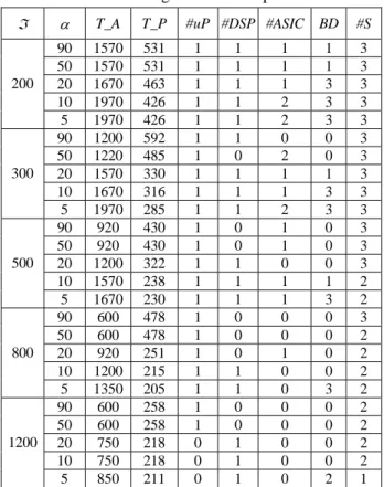
(5) 4: EXPERIMENTAL RESULTS In this section, two experiments are made to demonstrate the advantages of proposed ILP approach. The first experiment explains how pipelined scheduling, communication synthesis and DVS impact the system’s area and power, and shows the benefit of solving them simultaneously. The second experiment tests the ability of proposed approach to trade system’s throughput with area and power consumption. In these experiments, all the input data including task graph, PE library and implementation information are described in a text file. We wrote some PERL scripts to generate the corresponding ILP formulation from the file and the ILP solver LINGO was used to solve the ILP formulation with complex constraints on a PC with the 2.0 GHz processor and 2G main memory. The CPU run time for solving the ILP formulation in our experimental suite varied between 759 seconds and 2714.75 minutes. In the first experiment, a task graph with eight functional nodes and twelve communication edges is adopted. The available number of pipeline stage SMAX, available number of local bus BN, available number of each type of processors, and available number of each type of ASIC are 3, 3, 1, and 1, respectively. In addition, there are three discrete voltage levels for each type of processor, but only one voltage level for each ASIC. To compare with other optimal approaches, we simplify our ILP formulation to approximate the conventional optimal approaches and compare their design quality in terms of total area and total power consumption. Three approximate approaches (‘-dvs’, ‘-pipe’, and ‘-local’) are adopted in this experiment. The minus symbol means that the corresponding design step is removed from our ILP model. That is, ‘-dvs’ represents that DVS doesn’t be performed by removing the two lower voltage levels for all processors. The ‘-pipe’ is the approach without pipelined scheduling by setting the available pipeline stage number SMAX to 1. The ‘-local’ approach gives the limitation that all data are only transferred through the system bus and the number of available local bus BN is set to 0. Table 1 shows the results of experiment 1 under a fixed throughput constraint ℑ = 500. Different combinations of α and β are used to scale the importance of area and power as described in (13). We assume that 0 ≤ α ≤ 100 and β = 100 in the experiment. Choice of 0 < α < β implies that both area and power are considered simultaneously. The importance of both factors depends on the value of α and the resultant total area and power values are usually between the corresponding values obtained by the α = 0 and α = 100 extremes. The larger α means that area is more important in the design. In addition, OBJ used to evaluate the synthesis results of these approaches is obtained by followed formulation:. OBJ = [α ⋅ T_Area + (β−α) ⋅ T_Power] / 100 (23) T_A and T_P in Table 1 denote the T_Area and T_Power of synthesized system architecture. The results. show that our proposed approach can actually explore larger design space to obtain better solution than other approaches. The proposed approach is especially useful when reducing power consumption is the most important design goal (i.e., α is very small). By the design results with the combination of α = 5 and β = 100, DVS can achieve more significant power saving than pipelined scheduling and local bus communication. However, DVS seems unable to work very well when reducing system’s area is the main design goal. On the other hand, pipelined scheduling plays an important role in reducing both of area and power consumption. For example, the ‘-pipe’ approach in the combination of α = 90 and β = 100 gives a non-pipelined system architecture which consists of PEs with higher voltage level and additional local buses to satisfy throughput constraint. Therefore, larger area and more power consumption are required. Finally, transferring data through a local bus not only saves power than the system bus, but also increase the slack time (transferring data through local bus spends zero communication time). Therefore, local bus communication can further enhance the efficiency of DVS to reduce the power consumption. Similar to DVS, however, local bus communication seems to be unhelpful to reduce the system’s area. Table 1: Design results of experiment 1 option. α = 5, β = 100. α = 20, β = 100. α = 90, β = 100. (T_A, T_P) OBJ (T_A, T_P) OBJ (T_A, T_P) OBJ -dvs (1370, 377) 426.7 (1020, 410) 532.0 (600, 583) 598.3 -pipe (1220, 232) 281.4 (1070, 250) 414.0 (650, 575) 642.5 -local (1200, 204) 253.8 (1200, 204) 403.2 (600, 565) 596.5 our (1350, 188) 246.1 (1200, 204) 403.2 (600, 565) 596.5. The second experiment adopts another task graph with six nodes and seven edges. The available numbers of pipeline stage, local bus, microprocessor, DSP processor, and each type of ASIC are set to 3, 2, 1, 1, and 1, respectively. We varied the value of throughput constraint ℑ to generate the pipelined architectures with different system costs (area and power consumption). Moreover, various choices of α have been considered under the same throughput constraint ℑ to trade system area with system power consumption. Table 2 lists the design results including the total area (T_A), the total power consumption (T_P), the number of microprocessor used (#uP), the number of DSP processor used (#DSP), the number of ASIC used (#ASIC), the number of local bus used (BD), and the pipeline stage used (#S) for different throughput constraints. When throughput constraint ℑ is loose (1200), the resulted architecture may be non-pipelined (i.e. #S = 1) and has the least total area and total power consumption. When throughput constraint is tight, the resulted architecture is pipelined to satisfy the constraint and has lager total area and total power consumption. Moreover, various α values under the same throughput constraint ℑ lead to different system architectures. The. - 228 -.
(6) results in Table 2 indicate that the proposed ILP formulation is able to make the tradeoffs between system throughput and system cost as well as the total area and total power consumption. Table 2: Design results of experiment 2 ℑ. 200. 300. 500. 800. 1200. α. T_A. T_P. 90 50 20 10 5 90 50 20 10 5 90 50 20 10 5 90 50 20 10 5 90 50 20 10 5. 1570 1570 1670 1970 1970 1200 1220 1570 1670 1970 920 920 1200 1570 1670 600 600 920 1200 1350 600 600 750 750 850. 531 531 463 426 426 592 485 330 316 285 430 430 322 238 230 478 478 251 215 205 258 258 218 218 211. #uP #DSP #ASIC 1 1 1 1 1 1 1 1 1 1 1 1 1 1 1 1 1 1 1 1 1 1 0 0 0. 1 1 1 1 1 1 0 1 1 1 0 0 1 1 1 0 0 0 1 1 0 0 1 1 1. 1 1 1 2 2 0 2 1 1 2 1 1 0 1 1 0 0 1 0 0 0 0 0 0 0. BD. #S. 1 1 3 3 3 0 0 1 3 3 0 0 0 1 3 0 0 0 0 3 0 0 0 0 2. 3 3 3 3 3 3 3 3 3 3 3 3 3 2 2 3 2 2 2 2 2 2 2 2 1. [2] O. Ogawa, S. Bayon de Noyer, P. Chauvet, K. Shinohara, Y. Watanabe, H. Niizuma, T. Sasaki, and Y. Takai, “A practical approach for bus architecture optimization at transaction level,” in Proc. Design, Automation and Test in Europe Conference and Exhibition, pp. 176–181, 2003. [3] H. Liu and D. F. Wong, “Integrated partitioning and scheduling for hardware/software co-design,” in Proc. International Conference on Computer Design: VLSI in Computers and Processors, pp. 609–614, Oct. 1998. [4] R. Niemann and P. Marwedel, “An algorithm for hardware/software partitioning using mixed integer linear programming,” in Proc. Design Automation for Embedded Systems, vol. 2, pp. 165–193, March 1997. [5] S. A. Khayam, S. A. Khan, and S. Sadiq, “A generic integer programming approach to hardware/software codesign,” in Proc. IEEE Int. Multi Topic Conf., pp. 6–9, Dec. 2001. [6] R. P. Dick and N. K. Jha, “MOGAC: a multiobjective genetic algorithm for hardware-software cosynthesis of distributed embedded systems,” IEEE Transactions on Computer-Aided Design of Integrated Circuits and Systems, Vol. 17, No. 10, pp. 920–935, 1998. [7] L. Pontani and D. Dupont, “Scheduling and assignment for real-time embedded systems with resource contention,” in Proc. Euromicro Symp. on Digital System Design, pp. 55–61, Sept. 2003. [8] S. Banerjee and N. Dutt, “Efficient search space exploration for HW-SW partitioning,” in Proc. Int. Conf. on Hardware/Software Codesign and System Synthesis, pp. 122–127, 2004. [9] S. Bakshi and D. D. Gajski, “Partitioning and pipelining for performance-constrained hardware/software systems,” IEEE Trans. Very Large Scale Integr. (VLSI) Syst., Vol. 7, No. 4, pp. 419–432, 1999.. 5: CONCCLUSION Mapping, pipelined scheduling, communication synthesis, and DVS are important and strong inter-dependent design steps in embedded system design. This paper has proposed an ILP based approach to solve them simultaneously. The proposed approach took voltage selection into account while performing mapping, pipelined scheduling and communication synthesis to ensure that the design results can conform to the real situation. Experimental results have shown that the proposed ILP approach can generate the optimal pipelined architecture with the least total area and/or total power consumption for multimedia applications.. [10] K. S. Chatha and R. Vemuri, “Hardware-software partitioning and pipelined scheduling of transformative applications,” IEEE Trans. Very Large Scale Integr. (VLSI) Syst., Vol. 10, No. 3, pp. 193–208, 2002. [11] B. P. Dave and N. K. Jha, “COHRA: hardware-software cosynthesis of hierarchical heterogeneous distributed embedded systems,” IEEE Trans. Compu.-Aided Des. Integr. Circuits Syst., Vol. 17, No. 10, pp. 900–919, 1998. [12] B. P. Dave, G. Lakshminarayana, and N. K. Jha, “COSYN: Hardware-software co-synthesis of heterogeneous distributed embedded systems,” IEEE Trans. Very Large Scale Integr. (VLSI) Syst., Vol. 7, No. 1, pp. 92–104, 1999. [13] T. Ishihara and H. Yasuura, “Voltage scheduling problem for dynamically variable voltage processors,” in Proc. Int. Symp. on Low Power Electronics and Design, pp. 197–202, 1998.. 6: ACKNOWLEDGMENT This work was supported in part by the National Science Council, R.O.C., under Grant NSC 94-2213-E-110-050.. REFERENCES. [14] M. T. Schmitz, B. M. Al-Hashimi, and P. Eles, “Energy-efficient mapping and scheduling for DVS enabled distributed embedded systems,” in Proc. Design, automation and test in Europe Conf., pp. 514–521, March 2002.. [1] T. Yen and W. Wolf, Hardware-Software co-synthesis of distributed embedded systems. Kluwer academic publishers, 1996.. - 229 -.
(7)
數據
相關文件
Pessoal remunerado a tempo completo e a tempo parcial nas lotarias e outros jogos de aposta segundo o sexo e a profissão Number of full-time and part-time paid employees in the
Pessoal remunerado a tempo completo e a tempo parcial nas lotarias e outros jogos de aposta segundo o sexo e a profissão Number of full-time and part-time paid employees in the
The PE curriculum contributes greatly to enabling our students to lead a healthy lifestyle with an interest and active participation in physical and aesthetic
We compare the results of analytical and numerical studies of lattice 2D quantum gravity, where the internal quantum metric is described by random (dynamical)
Miroslav Fiedler, Praha, Algebraic connectivity of graphs, Czechoslovak Mathematical Journal 23 (98) 1973,
Personal development, health and physical education stage 6 syllabus.. New South Wales: Board of Studies New
* Before making a request from Interlibrary Loan service, please check the N TU Library online catalog to make sure the items are not NTU libraries' holdings.. * For
Type case as pattern matching on values Type safe dynamic value (existential types).. How can we
