國
立
交
通
大
學
資訊科學與工程系
碩
士
論
文
空間利用率及電磁干擾考量的電路線軌指派演算法
Utilization– And Crosstalk–Driven Track Assignment Algorithms
研 究 生:蔣孟欣
指導教授:李毅郎 博士
空間利用率及電磁干擾考量的電路線軌指派演算法
Utilization- And Crosstalk-Driven Track Assignment Algorithms
研 究 生:蔣孟欣 Student:Meng-Xin Jiang
指導教授:李毅郎 Advisor:Dr. Yih-Lang Li
國 立 交 通 大 學
資 訊 科 學 研 究 所
碩 士 論 文
A ThesisSubmitted to Institute of Computer Science and Engineering College of Computer Science
National Chiao Tung University in partial Fulfillment of the Requirements
for the Degree of Master
in
Computer Science and Engineering
Aug 2005
Hsinchu, Taiwan, Republic of China
空間利用率及電磁干擾考量的電路線軌指派演算法
學生:蔣孟欣 指導教授:李毅郎 博士
國立交通大學 資訊工程與科學系 碩士班
摘 要
隨著超大型積體電路製程技術邁入奈米時代,使得電子裝置的大小及線路的寬度都隨之 縮小,而且在相同層中,線路間的距離也變得越來越近。同時,晶片設計的執行脈衝頻率也 往上增加到十億赫茲甚至超過十億赫茲,如此在半導體製程技術及設計上的不斷進步導致很 嚴重的電阻電感電容干擾現象 ( 在兩相鄰且相互干擾的線路中容易造成訊號的錯誤、前後不 一致 )。因此在高速超大型積體電路的設計中,想辦法避免或滿足電磁干擾效應的重要性也 隨之提升。然而,在傳統的兩階段繞線 ( 全域繞線和精細繞線 ) 流程中,要解決這樣的問 題會使得整個流程變得複雜且沒有效率。因為在全域繞線中,沒有電路線軌的資訊,所以很 難去考量電磁干擾現象;而在精細繞線這原本就十分耗時的階段去考量此問題,只會增加 它大量的計算,使它的負擔變的更重。因為這些原因,有人便提出了在全域繞線及精細繞線 中併入一個中間的步驟,稱之為電路線軌指派。 先前著作有人用區域為主的方式在電路線軌指派時考慮電磁干擾效應,而區域為主的電 路線軌指派它的線軌利用率較差,導致在固定大小的指派區域中比較無法完成所有線路的指 派。我們在此篇著作提出兩個在點格式為主的系統下,同時考量線軌利用率跟電磁干擾的電 路線軌指派演算法 : 混合型區域為主電路線軌指派以及交換為主的電路線軌指派。此外,還 提出一個應用於非點格式系統的電路線軌指派演算法。混合型區域為主電路線軌指派演算法 首先將高度影響性的線路指派到奇數的電路線軌上,若奇數的電路線軌都擺完了,再使用區 域為主的方法將其餘的線路指派到偶數的電路線軌; 交換為主的電路線軌指派則是先產生一 個初始的電路線軌指派,再依據可容忍的電磁干擾效應限制,將電路分成關鍵型線路以及非 關鍵型線路 (超過可容忍的電磁干擾效應限制稱為關鍵型線路,反之則稱為非關鍵型線路), 最後透過交換的方式在所有電路皆滿足電磁干擾效應限制的前提下,減少整體的電磁干擾效 應; 非點格式系統的電路線軌指派演算法,是一種混合型區域為主電路線軌指派演算法的變 化,應用於非點格式系統上。實驗數據顯示,混合型區域為主電路線軌指派能比先前著作減少 42.6%的電磁干擾效應,而交換為主的電路線軌指派則有 46.8%的改善。除此之外,此兩 個演算法均如預期的一樣,指派失敗的線路比先前著作要少。至於非點格式系統的電路線軌 指派演算法,能確切的將不同線寬的電路指派到非點格式系統中,並且也考量了電磁干擾的 效應,算是電路線軌指派在非點格式系統的一項創舉。
Utilization- And Crosstalk-Driven Track Assignment Algorithms
Student: Meng-Xin Jiang Advisor:Dr. Yih-Lang Li
Institute of Computer Science and Engineering National Chiao Tung University
ABSTRACT
As the VLSI manufacturing technology advances to the Very Deep Submicron (VDSM) era, the device feature size shrinks and the minimum separation between two wires of the same layer is getting closer. Meanwhile, the operating clock rate of IC design is increasingly towards and above gigahertz. Such continuous progresses in semiconductor and design technologies bring serious RLC crosstalk that could easily introduce an inconsistent signal change between two adjacent and mutually interfering wires. Accordingly, avoiding crosstalk or satisfying crosstalk constraints for high-speed VLSI design is of growing importance. However, it is complicated and inefficient to solve the problem in conventional two-stage flow ( global routing and detailed routing ). The difficulty of minimizing crosstalk during global routing is that nets have no track information at this stage, while the difficulty for detailed routing is to increase the computation load on an already time-consuming task. Therefore, the TA, an intermediate stage between global routing and detailed routing, is incorporated with the routing flow.
Previous works of track assignment (TA) are the zone-based approaches. Zone-based TA may produce worse track utilization such that the assignment of all nets to the fixed-sized panel can not be completed. This work depicts two utilization- and crosstalk-driven TA algorithms: hybrid zone-based TA (HZTA) and switching-based TA (SBTA). HZTA places the highly impacted nets on the odd tracks first, and then apply the zone-based approach to complete the assignment of even tracks. SBTA first produces a utilization-driven TA, and then, divides the nets into critical nets and non-critical nets, where a critical net is the net whose coupling effect exceeds the coupling budget. It reduces the crosstalk by switching nets under the crosstalk budget satisfaction. Gridless TA is an application of HZTA. It not only can assign the variable nets exactly on a gridless environment, but also considers the coupling
effect. The experiment results display that HZTA can reduce more coupling effects than previous work by 42.6%, while SBTA algorithm can perform better crosstalk reduction by 46.8%. Besides, as expected, both HZTA and SBTA have fewer failed nets than previous work. Otherwise, Gridless TA is the first work about TA in gridless environment.
Acknowledgements
I am deeply grateful to my advisor, Dr. Yih-Lang Li for his continuous guidance, support, and ardent discussion throughout this research. His valuable suggestions help me to complete the thesis. Also I express my sincere appreciation to all classmates in my laboratory for their encouragement and help.
This thesis is dedicated to my parents and my families for their patience, love, encouragement, and long expectation.
Contents
Abstract (in Chinese)... I Abstract (in English)... III Acknowledgements...V List of Figures ...VII List of Tables...VIII
1 Introduction ... 1
1.1 Crosstalk and Track Assignment Overview... 1
1.2 Previous Works and Our Approach…... 2
2 Preliminaries……... 4
2.1 Routing and Crosstalk Model...4
2.2 Problem Formulation...5
3 The Utilization- and Crosstalk-Driven Track Assignment Algorithms...7
3.1 Hybrid Zone-Based Track Assignment ( HZTA )...7
3.2 Swap- and Move-Based Track Assignment ( SMTA )...9
O-Tree Based Gridless Track Assignment ( OTTA ) ...12
4 Experimental Results...27
5 Conclusions...30
List of Figures
Figure 1. A 10-net global routing result and the illustration of primary definitions... 5
Figure 2. An overlapping graph and the decreasing iterations of net degree... 8
Figure 3. The first step result of TPTA... 8
Figure 4. The maximum weighted bipartite matching graph... 9
Figure 5. The TPTA result of Fig. 1(a)... 9
Figure 6. SMTA algorithm ... 11
Figure 7. The initial track assignment of SMTA algorithm... 11
Figure 8. Swapping the critical IRoute 1 with IRoute 6... 12
Figure 9. Moving IRoute 2 to the topmost track... 12
Figure 10. Final result of SMTA... 12
Figure 11.(a)A T-compact placement(b)related vertical O-tree(c)extended vertical O-tree.. 14
Figure 12. A 19-net gridless global routing result on a panel... 15
Figure 13. An overlapping graph of Fig. 12... 15
Figure 14. The maximum clique is first completed in OTTA... 16
Figure 15. The result of the initial assignment of OTTA... 16
Figure 16. The extended O-tree of the assignment... 18
Figure 17. Node 4 is deleted from the extended O-tree... 19
Figure 18. The bottom sub-tree is plowed downwards... 20
Figure 19. The extended O-tree after Node 4 insert above Node 11... 21
Figure 20. A T-compact assignment after node insertion... 22
Figure 21. The final result after extended O-tree based refinement... 23
Figure 22.The assignment is partitioned into six pseudo rows... 24
Figure 23. The partial pseudo-row OLG of the assignment in Fig. 22... 25
Figure 24. A new pseudo-row order for crosstalk minimization... 25
List of Tables
Table 1. The information of test cases... 28
Table 2. The comparisons for three CTA algorithms... 28
Table 3. The test case information of OTTA... 29
Chapter 1
Introduction
1.1 Crosstalk and Track Assignment Overview
For high-speed design and embedding more components in an integrated circuit to enrich
its functions, the operating clock frequencies of designs are continuously increasing, and
semiconductor technology has also advanced to reach a nanometer scale. Smaller transistors
have smaller gate channel length, namely, shorter traveling distance for electrons and holes.
Smaller gate channel length achieves faster device switching; however, for interconnections,
slimmer wires suffer higher resistance since interconnection resistance is inversely
proportional to the product of wire width and height. Excess wire delay comes to be a critical
challenge for fast design closure. To cope with this side-effect, wires tend to be designed with
higher aspect ratios of wire height to wire width (height/width). Such design is helpful for
dealing with the problem of rising wire resistance yet does so at the cost of increasing
coupling capacitance between wires. Increasing coupling capacitance, which is a source of
signal integrity problems, is also impacted by smaller separation between wires than before.
Under the trend of ongoing device shrinkage, with associated decreases in wire width and
separation, interconnect optimization for high-performance System-on-Chip (SoC) design and
maintaining signal integrity become crucial for successful SoC design. Accordingly, crosstalk
avoidance or satisfaction of crosstalk constraints for high-speed VLSI design is of growing
importance. Modeling coupling capacitance [1, 2] and inductance [3, 4] has been well studied,
where coupling capacitance (Cc) is a short-ranged effect while coupling inductance is
long-ranged. The capacitance crosstalk is only considered in this work.
Traditional routing flow consists of global routing and detailed routing [5]. Global routing
usually partitions the whole routing region into sub-regions, i.e., global cells (GCells). Each
Global router generates a loose route constructed by a subset of global cells connecting the
terminals of the net without specifying the actual geometric layout wires. Steiner tree based [6,
7] and maze routing based [8, 9, 10] approaches have been applied to global routing. Detailed
routing is to find the actual wire segment for each net within the assigned global cells by the
global router. As the design complexity dramatically increases, the detailed routing consumes
increasing amounts of time, even with the aid of global routing. Therefore, the track
assignment [11], an intermediate stage between global routing and detailed routing, is
incorporated into the two-stage routing flow. Track assignment only deals with the nets that
pass through at least two global cells and places as much nets as possible on available tracks.
In this work, the processed net segment is called an IRoute. After track assignment, the
routing of most long nets has been finished and much runtime reduction in detailed routing is
realized.
1.2 Previous Works and Our Approach
On the other hand, crosstalk minimization during two-stage routing flow has been well
surveyed [12, 13, 14, 15]. The difficulty of minimizing crosstalk during global routing is that
nets have no track information at this stage, while the difficulty for detailed routing is to
increase the computation load on an already time-consuming task. The first investigation that
addresses the crosstalk-driven TA is developed in a multilevel routing system [16]. In their
work, the horizontal constraint graph (HCG), i.e., IRoute overlap graph, and the bipartite
assignment graph, that defines the assignability of each IRoute to the tracks, are well
integrated. The maximum subset of conflicting nets, that is equivalent to the maximum clique
in the HCG, is then found and assigned to the tracks one by one. The zone-based approach can
efficiently reduce the crosstalk; however, the TA result may have worse track utilization. In
this thesis, two capacitive crosstalk driven TA algorithms, namely, hybrid zone-based TA
(HZTA) and Swap- and Move-based TA (SMTA) are first proposed to obtain more crosstalk
grid-based TA problem. This thesis first proposes a gridless crosstalk-driven TA algorithm,
called O-tree based gridless TA (OTTA). Experimental results show that the first two
proposed algorithms achieve better track utilization and more crosstalk reduction by 42.49%
and 46.79%, respectively. Meanwhile, OTTA can obtain better crosstalk reduction for an
initial assignment.
The rest of this paper is organized as follows. Section 2 reviews the track assignment
problem and defines basic terminology. Section 3 presents HZTA, SMTA and OTTA
algorithms. Section 4 shows the experimental results. And finally, Section 5 makes
Chapter 2
Preliminaries
2.1 Routing And Crosstalk Models
In this work about grid TA, routing follows the restricted layer model, i.e., a routing layer
that is reserved the wiring in one direction has to pay high penalty for the move in
perpendicular direction. The routing direction of a layer is perpendicular to those on its
adjacent layers, and the wiring consists of Manhattan shapes. The routed nets have uniform
width rule and spacing rule on a layer, and may have variant width rules or spacing rules on
different layers.
Global routing distributes all the routed nets over the GCells without violation on each
GCell’s routing resource and with the objective of minimizing total wire length. Based on
the design rule of the routing pitch of a routing layer and the area of a GCell, the routing
resource of a GCell is considered as separate and equal-distance grid lines, called tracks. The
routed nets must be placed on the tracks. The purpose of track assignment is to reduce the
burden of detailed router and to produce more straight wiring result, therefore long nets are
more important than short nets. The net segment that passes through a whole GCell is a long
net and called an IRoute, which track assignment only deals with. For example in Fig. 1(b),
net a, b and c are IRoutes, but d is not. A panel is composed of a series of GCells in a row or a
column and a horizontal (vertical) panel only contains horizontal (vertical) tracks. Fig. 1(b)
shows a routing region consisting of 6×13 GCells and an example for the above definitions. Fig. 1(a) shows a track assignment result after global routing for a horizontal panel. Note that
The simple Cc model in [17] is applied in this work. Since Cc drops fast as two adjacent
nets become farther, for simplifying the coupling model, the Cc is assumed to be only induced
between two adjacent nets. Also, two net segments on different layers and in perpendicular
directions are free of inducing Cc. Furthermore, all two adjacent tracks are of equal distance,
Cc between two adjacent nets can be simply estimated using their overlapping length.
2.2 Problem Formulation
Let L = {lri| 0 ≤ i < l} be the set of routing layers. For layer lri, the layer plane consists of ai
panels denoted by pli,j, where 0 ≤ j < ai. The panel pli,j has to accommodate gi,j IRoutes
indicated by iri,j,k, where 0 ≤ k < gi,j. Let Ti,j be the track set on the panel pli,j, and it contains ri,j
represented by its set of constituent contiguous intervals, i.e., tri,j,m ≡ Uiti,j,m,n, where iti,j,m,n is
an interval of track tri,j,m. Each interval, say iti,j,m,n, is either
• A blocked interval, where every iri,j,k can not be assigned,
• An occupied interval, where ∃k, iri,j,k has been assign or
• A free interval, where ∀0 ≤ k < gi,j, no iri,j,k has been assigned.
An IRoute iri,j,k is said to be assignable to a track tri,j,m, tri,j,m ≡ Uiti,j,m,n, iff ∃n, iti,j,m,n ∩ iri,j,k
≠ ∅. If iti,j,m,n ∩ iri,j,k = iri,j,k, the entire IRoute can be assigned to the interval; otherwise, the
IRoute has to be split to fit the interval. Besides, the cc induced by two adjacent IRoutes, say
iri,j,k1 and iri,j,k2, is indicated by cci,j,k1,k2. Therefore, the crosstalk-driven track assignment
(CTA) problem can be defined as:
Crosstalk-Driven Track Assignment Problem: Given a set of tracks ℑ = {tri,j,m|0 ≤ i < l,
0 ≤ j < ai, and 0 ≤ m < ri,j} and a set of IRoutes L = {iri,j,k|0 ≤ i < l, 0 ≤ j < ai, and 0 ≤ k < gi,j},
and a cost function Φ: L× ℑ → N which stands for the crosstalk cost of assigning an IRoute to a track, find an assignment to minimize the total crosstalk:
(1)
.
1 0 1 0 1 0 1 1 2 2 , 1 , , ,∑ ∑ ∑
−∑
= − = − = ≠ l i a j g k k k k k j i i i jcc
Since the above formulation has reserved a specific layer for an IRoute, a layer assignment
algorithm [16] has to be applied before starting track assignment if the global routing result
does not contain layer information. Alternatively, a multilayer, instead of single layer, global
Chapter 3
The Utilization- And Crosstalk-Driven
Track Assignment Algorithms
3.1 Hybrid Zone-Based Track Assignment ( HZTA )
HZTA first completes the assignment of the odd tracks and then the even tracks. The odd
tracks accommodate the vertices of higher degree to separate these highly impacted nets. The
IRoute overlapping graph ( IRoute OLG ) is constructed following the rules: each vertex of an
IRoute OLG corresponds to an IRoute, and an edge exists between two vertices if their related
IRoutes have nonzero overlapping length, i.e., they can not be placed on the same track. For
each odd track, HZTA first assigns the IRoute of the maximum degree to the odd tracks. After
each assignment, the related vertex of the assigned IRoute is removed from the IRoute OLG.
For the remaining available track space, the process of finding, assigning, and removing the
vertex of the maximum degree is repeated until there is no unassigned assignable IRoute to
the available track space of current odd track. If two vertices tie in the vertex degree, IRoute
length is the second factor to be considered.
The assignment problem of the even tracks is transformed into a maximum-weighted
bipartite matching problem. A maximum clique is first found from the remaining IRoute OLG.
The vertices on the left side of the bipartite graph stand for the IRoutes in the maximum
clique, and the vertices on the right side represent the even tracks. If an IRoute can be
assigned to a track, an edge is present to connect these two related vertices in the bipartite
graph. The cost of an edge indicates the crosstalk reduction gain of assigning the IRoute to the
track. The crosstalk reduction gain is defined as follows. For an IRoute in the maximum
of the maximum induced crosstalk has a cost of zero. The cost of other edge is calculated by
subtracting its induced crosstalk from the maximum crosstalk. Finally, the crosstalk-driven
assignment of the IRoutes in the maximum clique is equivalent to find a maximum-weighted
bipartite matching in the constructed graph. The assigned maximum clique is removed from
the IRoute OLG, and the same process continues until all IRoutes are assigned to the even
tracks or there is no assignable IRoute to the even tracks. Figure 2~5 show an example of
3.2 Swap- and Move-Based Track Assignment (SMTA)
SMTA is to minimize the total crosstalk under the constraint of a crosstalk budget to all
IRoutes, or the goal of SMTA is to find a track assignment with minimum total coupling
capacitance based on a given crosstalk budget for each IRoute. The problem can be
formulated as follows: , min , , , 1 0 1 0 1 0 1 1 2 2 , 1 , , max 2 2 , , , ,
∑ ∑ ∑ ∑
∑
− = − = − = ≠ ≠ ∀ ≤ l i a j g k k k k k j i k k k k j i i ij cc k j i C cc to subject (2)where Cmax is the given crosstalk budget.
SMTA starts from an initial TA produced by assigning the IRoutes in a decreasing order of
assigned to the same track until the track can not accommodate any unassigned IRoute.
Subsequently, its top adjacent track is considered as next available track. Based on the initial
TA, all IRoutes can be classified into critical and non-critical. An IRoute is said to be critical
if its induced coupling capacitance exceeds the specified crosstalk budget. SMTA deals with
the critical IRoutes in a decreasing order of the excess coupling capacitance, which is
obtained by subtracting Cmax from the induced coupling capacitance. The unassigned IRoute
with largest excess coupling capacitance is called the most critical IRoute. SMTA moves the
most critical IRoute or swaps it with another IRoute to make it become non-critical. More
specifically, all tracks are examined to determine if there is available space in another track to
accommodate the most critical IRoute to make it become non-critical or if the most critical
IRoute can become non-critical by swapping it with another IRoute. If this fails, we try to
move or swap its top or bottom neighbouring IRoutes to reduce its induced coupling
capacitance so that the constraint can be satisfied. Each move or swap is regarded as legal
only if it will not produce a new critical IRoute. SMTA will report a failure if current most
critical IRoute can not become non-critical after the above operations. If all critical IRoutes
become non-critical, the same move and swap procedure is applied to each IRoute to reduce
the total coupling capacitance. Now, each move or swap is legal if the total coupling
capacitance decreases after the move or swap and it does not produce any new critical IRoute.
Figure 6 displays the SMTA algorithm.
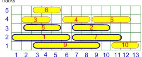
Figures 7-10 show an example of performing SMTA under a coupling capacitance
constraint of 6 overlapping GCells length for each IRoute. Figure 7 displays the initial TA,
where the IRoutes 1, 2, 7, 8 and 9 are critical IRoutes and IRoute 1 is the most critical IRoute.
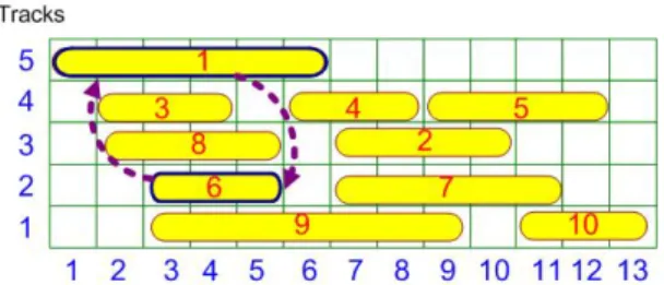
After examining all tracks, IRoute 1 can become non-critical by swapping IRoutes 1 and 6; at
the same time, IRoutes 8 and 9 also become non-critical, as shown in Fig. 8. Now only
IRoutes 2 and 7 are critical. After examining all tracks, moving IRoute 2 to the topmost track
non-critical, as shown in Fig. 9. Finally, the move and swap procedure is applied to each
IRoute to determine if there is any further reduction on the coupling capacitance. One swap
for IRoutes 3 and 6 and one move for IRoute 4 from track 4 to track 3 are feasible in this case,
as shown in Fig. 10.
Algorithm : SMTA
Input : A global routing result in a panel Output : A coupling-driven track assignment begin
1. Construct the IRoute OLG and calculate the degrees of all vertices; 2. Classify all IRoutes into critical and non-critical;
3. Sort the critical IRoutes in a decreasing order of the excess coupling capacitance; 4. for the most critical IRoute in the sorting order
5. Select the best track where it can move to make itself become non-critical or the best IRoute with which it can swap to make itself become non-critical;
6. if (current IRoute is still critical)
7. Try to move or swap its adjacent IRoutes to make it become non-critical; 8. if (current IRoute is still critical) report failure;
else remove current IRoute from the sorting list; 9. for each IRoute
10. Select the best track to move to reduce the induced coupling capacitance or the best IRoute to swap with to reduce the induced coupling capacitance;
11. Try to move or swap its adjacent IRoutes to reduce the induced coupling capacitance;
end
Figure 6. SMTA Algorithm.
Figure 8. Swapping the most critical IRoute 1 with IRoute 6 can make critical IRoutes 1, 8
and 9 become non-critical.
Figure 9 Critical IRoutes 2 and 7 become non-critical by moving IRoute 2 to the topmost
track.
Figure 10. Total coupling capacitance can be further reduced by swapping IRoutes 3 and 6
and moving IRoute 4 from track 4 to track 3.
3.3 O-Tree Based Gridless Track Assignment ( OTTA )
In this chapter, an O-tree based track assignment is proposed to deal with variable-width
and variable-space IRoutes. To our knowledge, this is the first study to discuss gridless track
assignment. From the observations in [4, 19], the two factors heavily affecting coupling
capacitance are the space and overlap length between two wires. One important characteristic
for a gridless routing problem is different wire width and space rules for the nets. The
about 0.4% to 7% coupling effect variation while the wire width is enlarged twice or even
triply. Therefore, the coupling effect estimation ignores the wire width and the model
presented in Chapter 2.1 is applied for the gridless track assignment problem. The space
between any two adjacent IRoutes is assumed to be fixed in the following discussion. The
discussion of extension of dealing with variable space rules will be outlined in the end of this
chapter.
Assume that the space between any two adjacent IRoutes is sp, the IRoutes are over-sized
by sp/2 to guarantee the separation legality between IRoutes. Therefore, the over-sized IRoute
can overlap with its adjacent IRoutes and only these overlapping adjacent IRoutes are
considered to induce coupling capacitance, that is, any two IRoutes, which has a non-zero
separation between them, is free of crosstalk effect. After over-sizing original IRoutes, the
gridless track assignment problem becomes a special placement problem. Each over-sized
IRoute can be regarded as a block with a constraint of locating at fixed x-coordinate. The
objective is to find a complete placement of minimum block abutting length within a routing
region of fixed height. One important thing for placement is how to represent and maintain
the contour of partial placement. B*-tree [20]and O-tree [21] are two well-known methods to
represent non-slicing placement. B*-tree is ideal for 2-dimensional move and O-tree is ideal
for one-dimensional move. This study applies O-tree to represent the assignment for fast
IRoute swap and move. The O-tree of a placement can be constructed as follows. Assume the
placement is a T-compact placement, where there is no block that can be shifted upwards from
current position with other blocks fixed. For a vertical O-tree, there is a root node on the top
to represent the top boundary and there is a node representing each block. The root node has
an edge directing to the nodes whose top border is located at the top boundary. For two block
nodes, say bi and bj, there is an edge from bi to bj if bi and bj abut and bi is on the top of bj. In
this study, the O-tree is enhanced by additionally adding an edge between two blocks with
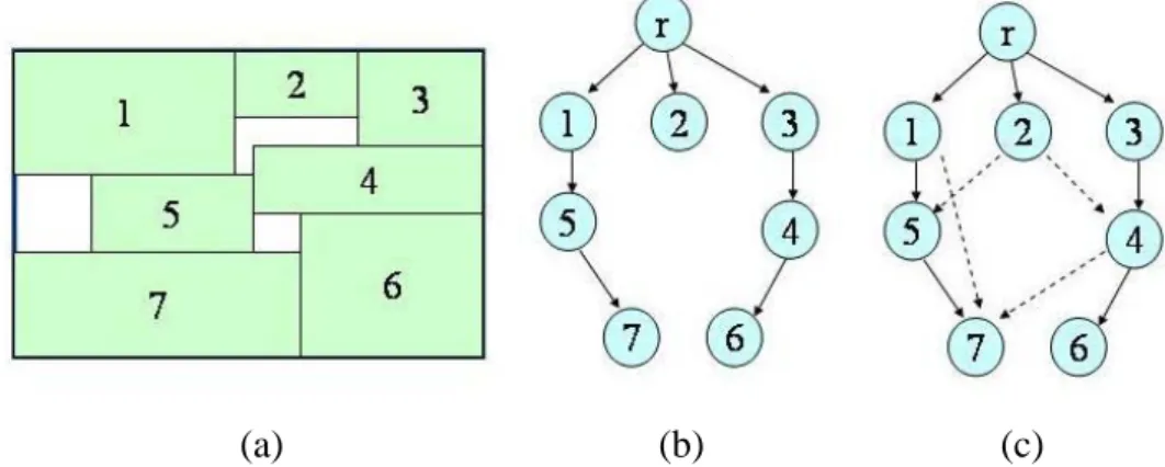
11(a) shows a T-compact placement, Fig. 11(b) shows its related vertical O-tree and Fig. 11(c)
demonstrates the extended vertical O-tree, where the dashed edges are the edges that do not
appear in the O-tree. In Fig. 11(a), blocks 2 and 7 have non-zero overlapping, but there is no
directed edge between them since they are separated by blocks 4 and 5. On the contrary,
blocks 1 and 7 can see each other, so there is an edge from block 1 to block 7.
(a) (b) (c)
Figure 11. (a) A T-compact placement; (b) related vertical O-tree; (c) extended vertical O-tree.
OTTA contains three steps: (1) initial assignment, (2) extended O-tree based assignment
refinement (EOAR), and (3) sub-panel rearrangement.
(1) Initial assignment: the goal of initial assignment is a fast production of an assignment
with good utilization. For grid-based track assignment, left-edge algorithm can be well
applied to obtain a utilization-driven initial assignment. Since gridless track
assignment probably produces uneven partial assignment, it is hard to regard the
region as row by row. Considering the crosstalk minimization objective, initial
assignment combines the minimum weighted Hamiltonian path on the maximum
clique and similar concept to left-edge algorithm to balance crosstalk minimization
and track utilization. An OLG is first established and a maximum clique is found. The
IRoutes in the maximum clique is assigned to the tracks in the order of a minimum
weighted Hamiltonian path [16]. After minimizing the crosstalk induced by the most
congested IRoute group, the unassigned IRoutes, which locate at the right side of the
remaining IRoutes are processed in the sorting order and each IRoute is assigned to
the topmost available space. The unassigned IRoutes, which locate at the left side of
the partial assignment, is sorted by their right borders in a decreasing order. Each
IRoute is also assigned in the sorting order to the topmost available space. Figures
(2) Extended O-tree based assignment refinement (EOAR): after the initial assignment is
produced, the corresponding extended O-tree of the over-sized IRoute placement is
established. Each node of the extended O-tree stands for an IRoute and there exists an
edge between two IRoutes if there is a non-zero vertical projection between them.
Each edge contains two costs, that is, overlap length and separation distance. Since the
over-sized IRoute in the placement has considered the separation rule, two over-sized
IRoutes separated by non-zero space are assumed to be free of crosstalk effect. Four
operations, DeleteNode, InsertNode, PlowTree, and CompactTree, on the O-tree are
supported to perform crosstalk minimization. InsertNode is adding a node to the
O-tree and DeleteNode is deleting a node from the O-tree. PlowTree is to reserve a
space for a node insertion. PlowTree is to plow all the nodes whose vertical range
contains a given horizontal line, called plow line, downwards by a distance of the
height of the block to be inserted. For a node insertion between two nodes, say bt (on
the top) and bb (on the bottom), the extension line of the top border of the bottom node
bb is the plow line. It seems that it is more efficient to perform PlowTree if only the
nodes whose horizontal range overlaps with the node to be inserted rather than all the
nodes that intersect with the plow line. As a matter of fact, plowing all nodes can
guarantee the success of a node insertion. For example, if a node is to be inserted on
the top of Node 11, as shown in Fig. 17, and the plowing distance is larger than the
separation distance between blocks 2 and 8, then the node insertion will fail with only
plowing the sub-tree of Node 11. CompactTree is to compact the blocks upwards to
make the placement T-compact. A node is said to be movable if all its incident edges
have non-zero distance cost. CompactTree is achieved by applying breadth-first search
on the extended O-tree to pull upwards those movable nodes. The height of an
assignment is the maximum path length, where a path length is the sum of the
along the path. The total coupling capacitance cost is the total overlap length of all
zero-separation edges. Figure 16 demonstrates the extended O-tree of the assignment
in Fig. 15.
EOAR performs the same procedure for each node. For each node, EOAR first
deletes the node from the extended O-tree and then inserts it on the top of all nodes
overlapping with it one at a time. The assignment of minimum crosstalk effect is
realized and CompactTree follows to make the assignment T-compact. EOAR allows
each IRoute to move far away and only considers the crosstalk minimization
individual IRoute and its neighbors. Further crosstalk reduction can be achieved by
(3) Sub-panel rearrangement: considering the global crosstalk effect, the assignment on
a panel can be regarded as assignments on several sub-panels. For example, the
assignment in Fig. 22 can be split into six sub-panels. Rearrangement of these
sub-panels can further reduce crosstalk effect. A sub-panel OLG is first constructed,
where each node in the graph represents a sub-panel and there are two directed edges
between any two nodes. Since the top and bottom contours of a sub-panel are not
symmetrical, two sub-panels can be assigned in two ways. The cost of an edge is the
total overlap length of two sub-panels associated with the end nodes of the edge.
When calculating the overlap length of two sub-panels, only the over-sized IRoutes,
which touch the abutting border, rather than the whole boundary contours are
considered because two over-sized IRoutes with non-zero separation is free of
crosstalk effect in our model. Two directed edges between two sub-panels can be
regarded as a pseudo edge and the sub-panel OLG can be treated as a complete
After the assignment is partitioned into as many sub-panels as possible, as
shown in Fig. 22, the crosstalk minimization problem can be formulated as the
problem of finding the minimum weighted Hamiltonian path (MWHP) on the
sub-panel OLG. The heuristics algorithm for finding MWHP on an IRoute OLG in
[16] can be well applied with little modification. The MWHP searching process
starts from the node with maximum inward edge cost or maximum outward edge
cost. If the maximum cost is caused by the outward edge, the sub-panel is mirrored
and then placed on the top of the panel. Next, the outward edge of the least cost of
the start node and its another end node are included in the Hamiltonian path if
another end node has been visited yet before. The new included node becomes the
new start node in next iteration. This process continues until all nodes have been
visited. The node sequence along the MWHP forms a new sub-panel order on the
panel. Figure 24 shows a new sub-panel order for the assignment in Fig. 22. If
original panel is very loose and there are empty sub-panels, they will be inserted to
separate the sub-panels to reduce the overlap length; furthermore, local refinement
such as pulling IRoutes upwards if there are space on tier top can compact the
assignment without increasing crosstalk effect. Figure 25 shows the final
Chapter 4
Experimental Results
The proposed HZTA, SMTA and OTTA algorithms were implemented in the C++ language.
The tests for benchmark circuits were executed on an Intel 2.4GHz PC with 768M RAM. For
grid-based track assignment, Table 1 lists the statistics of eight small cases, which come from
the examples of channel routing papers, and eight benchmark circuits. To compare with the
work in [16], the TA algorithm in [16] is implemented and performed on the same machine.
Table 2 compares the test results with those in [16]. The cost in the first column of each
method in Table 2 is the total crosstalk of TA, i.e., the total overlapping length in the panel.
The TA of [16] fails to complete the assignment for test1. Both HZTA and SMTA complete
the assignment of test1; furthermore, SMTA obtains less crosstalk than the method in [8].
Since the panels in S-series benchmarks are very loose, HZTA and SMTA can produce
assignments with zero overlap length. The algorithm in [16] does not consider the case of
loose panel, so it still produces assignment of non-zero overlap length. To avoid unjust
comparison, the crosstalk reduction rate does not count in the results of these benchmark
circuits. In summary, HZTA and SMTA complete the assignment and achieved 42.49% and
46.79% better crosstalk reduction, respectively, than the method in [16]. The crosstalk budget
of SMTA is basically assigned equal to the maximum overlap length in HZTA and it can be a
little adjusted to acquire better results.
For gridless track assignment, the IRoute width is generated randomly. The wire width of
five percent IRoutes is tripled and the wire width of fifty percent IRoutes is doubled, while the
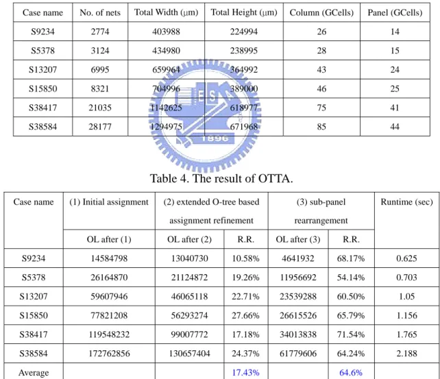
reduction rate of entire overlap length in each stage. Sub-panel rearrangement achieves more
gain than extended O-tree based assignment refinement.
Table 1. The information of test cases.
Case name No. of nets Track size Panel length (No. of GCells)
test1 12 5 20 test2 14 6 18 test3 9 5 13 test4 9 5 12 test5 12 5 14 test6 15 5 15 test7 12 5 23 test8 10 5 12 mcc1 1694 20 47 mcc2 7118 20 169 S9234 2774 20 14 S5378 3124 20 15 S13207 6995 20 24 S15850 8321 20 46 S38417 21035 20 75 S38584 28177 20 85
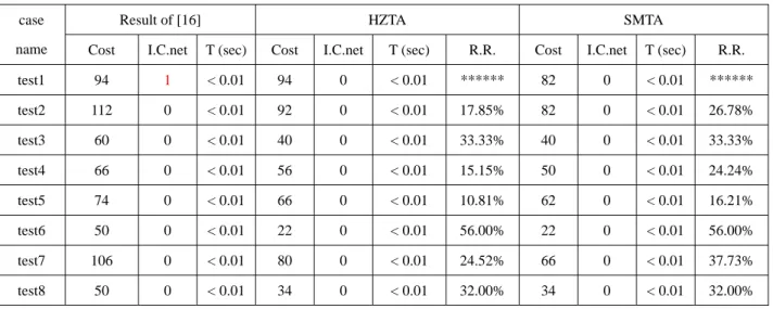
Table 2. The comparisons for three CTA algorithms.
Result of [16] HZTA SMTA
case
name Cost I.C.net T (sec) Cost I.C.net T (sec) R.R. Cost I.C.net T (sec) R.R. test1 94 1 < 0.01 94 0 < 0.01 ****** 82 0 < 0.01 ****** test2 112 0 < 0.01 92 0 < 0.01 17.85% 82 0 < 0.01 26.78% test3 60 0 < 0.01 40 0 < 0.01 33.33% 40 0 < 0.01 33.33% test4 66 0 < 0.01 56 0 < 0.01 15.15% 50 0 < 0.01 24.24% test5 74 0 < 0.01 66 0 < 0.01 10.81% 62 0 < 0.01 16.21% test6 50 0 < 0.01 22 0 < 0.01 56.00% 22 0 < 0.01 56.00% test7 106 0 < 0.01 80 0 < 0.01 24.52% 66 0 < 0.01 37.73% test8 50 0 < 0.01 34 0 < 0.01 32.00% 34 0 < 0.01 32.00%
mcc1 18088 0 1.382 834 0 9.953 95.38% 646 0 1.406 96.42% mcc2 227842 0 21.453 5968 0 180.828 97.38% 3590 0 10.06 98.42% S9234 462 0 0.047 0 0 0.687 ****** 0 0 0.062 ****** S5378 896 0 0.062 0 0 0.812 ****** 0 0 0.083 ****** S13207 2238 0 0.156 0 0 2.015 ****** 0 0 0.171 ****** S15850 3114 0 0.172 0 0 2.266 ****** 0 0 0.203 ****** S38417 5448 0 0.432 0 0 5.969 ****** 0 0 0.484 ****** S38584 7548 0 0.609 0 0 7.313 ****** 0 0 0.631 ****** Average 42.49% 46.79%
I.C. net : incomplete net; T(sec) : runtime ; R.R. (reduction rate) : ( cost of [16] – cost of HZTA(SMTA) ) / ( cost of [16] ).
Table 3. The test case information of OTTA.
Case name No. of nets Total Width (µm) Total Height (µm) Column (GCells) Panel (GCells)
S9234 2774 403988 224994 26 14 S5378 3124 434980 238995 28 15 S13207 6995 659964 364992 43 24 S15850 8321 704996 389000 46 25 S38417 21035 1142625 618977 75 41 S38584 28177 1294975 671968 85 44
Table 4. The result of OTTA.
(1) Initial assignment (2) extended O-tree based assignment refinement
(3) sub-panel rearrangement Case name
OL after (1) OL after (2) R.R. OL after (3) R.R.
Runtime (sec) S9234 14584798 13040730 10.58% 4641932 68.17% 0.625 S5378 26164870 21124872 19.26% 11956692 54.14% 0.703 S13207 59607946 46065118 22.71% 23539288 60.50% 1.05 S15850 77821208 56293274 27.66% 26615526 65.79% 1.156 S38417 119548232 99007772 17.18% 34013838 71.54% 1.765 S38584 172762856 130657404 24.37% 61779606 64.24% 2.188 Average 17.43% 64.6%
Chapter 5
Conclusions
This thesis proposes three utilization- and crosstalk-driven TA algorithms, HZTA, SMTA,
and OTTA. HZTA processes odd-numbered tracks row by row and even-numbered tracks
zone by zone, while SMTA reduces crosstalk effect by moving and swapping critical IRoutes
based on an initial assignment. In this thesis, the first griddles TA algorithm is also proposed.
Based on the proposed extended O-tree and the four underlying operations on the extended
O-tree, say DeleteNode, InsertNode, PlowTree, and CompactTree, each IRoute has chance to
escape from the original position assigned by the initial assignment through the above four
operations. Global crosstalk reduction can be further achieved by sub-panel rearrangement.
Experimental results show that HZTA has larger crosstalk reduction rate by 42.49% than the
result in [16], while SMTA algorithm reduced crosstalk 46.79%. Both HZTA and RBTA can
complete the assignment for all test cases. Finally, OTTA can reduce the coupling effects by
Bibliography
[1] A. B. Kahng and S. Muddu, “New Efficient Algorithm for Computing Effective
Capacitance,” Proceeding of International Symposium on Physical Design, pp.
147–151, Apr. 1998.
[2] S. Tani, Y. Uchida and M. Furuie, “Parasitic Capacitance Modeling for Multilevel
Interconnects,” Asia-Pacific Conference on Circuits and Systems, Vol. 1, pp. 28-31,
Oct. 2002.
[3] S. Tani, Y. Uchida and M. Furuie, “Parasitic Capacitance Modeling for Multilevel
Interconnects,” Asia-Pacific Conference on Circuits and Systems, Vol. 1, pp. 28-31, Oct.
2002.
[4] S. W. Tu, W. Z. Shen, Y. W. Chang and T. C. Chen, “On-Chip Inductance modeling for
coplanar interconnect structure,” Proceeding of IEEE International Symposium on
Circuit and System, Vol 3, pp. 787-790, 2002.
[5] S. M. Sait and H. Youssef, “VLSI physical design automation,” World Scientific
Publishing, 1999.
[6] A. Kahng and G. Robins, “A New Class of Steiner Tree Huristics with Good
Performance the Iterated 1-Steiner Approach,” IEEE/ACM International Conference on
Computer Aided Design,1990.
[7] H. Zhou, “Efficient Steiner Tree Construction Based on Spanning Graphs,” IEEE
Transactions on Computer Aided Design, pp. 704-710, May 2004.
[8] Lee, C. Y, “An Algorithm for Path Connections and Its Applications,” IRE Trans.
Electronic Computers, pp. 346-365, Sep. 1961.
100-102, 1978.
[10] S. W. Hur, A. Jagannathan and J. Lillis, “Timing Driven Maze Routing,” International
Symposium on Physical Design, pp.208-213, Apr. 1999.
[11] S. Batterywala, N. Shenoy, W. Nicholls and H. Zhou, “Track assignment : A Desirable
Intermediate Step Between Global Routing and Detail Routing,” IEEE/ACM
International Conference on Computer Aided Design, pp. 59 – 66, Nov. 2002.
[12] H. Zhou and D. F. Wong, “Global Routing with Crosstalk Constraints,” Design
Automation Conference, pp.374-377, May 1998.
[13] J. Xiong and L. He, “Full-Chip Routing Optimization With RLC Crosstalk
Budgeting,” IEEE Transactions on Computer Aided Design, pp. 366-377, Mar. 2004.
[14] J. D. Cho, S. Raje and M. Sarrafzadeh, “Crosstalk-Minimum Layer Assignment,”
IEEE Custom Integrated Circuits Conference, pp. 29.7.1-29.7.4, May 1993.
[15] Di Wu, J. Hu, R. Mahapatra and M. Zhao, “Layer Assignment for Crosstalk Risk
Minimization,” Design Automation Conference, pp. 159-162, Jan. 2004.
[16] T. Y. Ho, Y. W. Chang, S. J. Chen and D.T. Lee, “A Fast Crosstalk- and
Performance-Driven Multilevel Routing System,” IEEE/ACM International
Conference on Computer Aided Design, pp. 382-387, Nov. 2003.
[17] T. Gao and C. L. Liu, “Minimum Crosstalk Channel Routing,” IEEE/ACM
International Conference on Computer Aided Design, pp. 692-696, 1993.
[18] L. E. Liu and C. Sechen, “Multi-Layer Chip-Level Global Routing Using an Efficient
Graph-based Steiner Tree Heuristic,” Proceeding of the European Design and Test
Conference, pp. 331-318, 1997.
[19] L. He and M. Xu, “Modeling and Layout Optimization for On-Chip Inductive
Coupling,” U. of Wisconsin at Madison, Technical Report ECE-00-1, Dec 1999.
[20] Y.C. Chang, Y. W. Chang, G. M. Wu, and S. W. Wu, “B*-trees : A New Representation
Conference, pp. 458-463, June 2000.
[21] P. N. Guo, C. K. Cheng, and T. Yoshimura, “An O-tree Representation of Non-Slicing
Floorplan and Its Applications,” Annual ACM IEEE Design Automation Conference,