Upstream power equalization in a gigabit passive
optical network
Chien-Hung Yeh*1, Dar-Zu Hsu2, Sien Chi3 1
*Information and Communications Research Laboratories,
Industrial Technology Research Institute, Chutung, Hsinchu 310-40, Taiwan
2Information and Communications Research Laboratories,
Industrial Technology Research Institute, Chutung, Hsinchu 310-40, Taiwan
3Department of Photonics and Institute of Electro-Optical Engineering,
National Chiao Tung University, Hsinchu 300-10, Taiwan
Department of Electrical Engineering, Yuan Ze University, Chungli 320-03, Taiwan *Corresponding author: [email protected]
Abstract: We propose a technique for achieving equalized power in upstream traffic in the gigabit passive optical network (G-PON). A simple power equalizer based on a Fabry–Perot laser diode (FP–LD) is proposed and demonstrated experimentally. By the proposed scheme, the different upstream powers can be equalized. As a result, a 20 dB dynamic upstream power range from −5 to −25 dBm, having a 1.7 dB maximal power variation, is attained. Moreover, the performance of the proposed configuration is also discussed.
©2007 Optical Society of America
OCIS codes: (060.2330) Fiber optics communications; (060.0060) Fiber optics and optical communications
References and links
1. W. Noell, P.-A. Clerc, L. Dellmann, B. Guldimann, H.-P. Herziq, O. Manzardo, C. R. Marxer, K. J. Weible, R. Dandiker, and N. de Rooij, “Applications of SOI-based optical MEMS,” IEEE J. Sel. Top. Quantum Electron. 8, 148–154 (2002).
2. A. Godil, “Diffractive MEMS technology offers a new platform for optical networks,” Laser Focus World 38, 181–185 (2002).
3. S.-S. Lee, J.-U. Bu, S.-Y. Lee, K.-C. Song, C.-G. Park, and T.-S. Kim, “Low-power consumption
polymeric attenuator using a micromachined membrane-type waveguide,” IEEE Photon. Technol. Lett. 12, 407–409 (2000).
4. S.-S. Lee, Y.-S. Jin, and Y.-S. Son, “Variable optical attenuator based on a cutoff modulator with tapered waveguides in polymers,” J. Lightwave Technol. 17, 2556–2561 (1999).
5. Y. Park, C. Lim, and I. Jung, “ONU power equalization of Ethernet PON system,” IEEE Photon. Technol. Lett. 16, 1984–1886 (2004).
6. D. E. Dodds and M. J. Sieben, “Fabry–Pérot laser diode modeling,” IEEE Photon. Technol. Lett. 7, 254– 256 (1995).
7. C. H. Yeh, C. C. Lee, Y. W. Hsu, and S. Chi, “Fast wavelength-tunable laser technique based on a Fabry– Perot laser pair with optical inter-injection,” IEEE Photon. Technol. Lett. 16, 891–893 (2003).
1. Introduction
Advantages of FTTx networks are their enormous capacity and high flexibility over the other telecommunication networks in the fiber access domain. Time-division-multiplexed passive optical networks (TDM-PONs) are emerging as a viable choice for the next generation FTTx broadband access networks. PON is a point-to-multipoint fiber optical network with no active elements in the signal’s path. Recently, products in agreement with the Broadband PON (B-PON) standard have come into existence. Moreover, products for Gigabit PON (G-(B-PON) as well as for Ethernet PON (E-PON) are emerging. The point-to-multipoint connectivity between the optical line terminal (OLT) and multiple optical network units (ONUs) is obtained by employing a passive branching device at the remote node (RN). Data traffic from an OLT to an ONU is called “downstream” (point-to-multipoint), and traffic from an ONU to
the OLT is called “upstream” (multipoint-to-point). Two wavelengths are used: typically 1310 nm (λup) for the upstream transmission and 1490 nm (λdown) for the downstream transmission.
Because the transmission lengths of each ONU to OLT are different, the upstream signals arrive at the OLT with various power levels. In addition, the auto-gain control (AGC) and clock and data recover (CDR) processes of upstream signals should be completed on constant power level within 44 ns in a G-PON system. The signal processing time of G-PON is shorter than that of E-PON (within 440 ns). In order to overcome the problem, the effective method is to adjust each upstream power in equal level at the OLT. To obtain the equal upstream powers in a G-PON, several variable optical attenuators (VOAs) [1-4] can be used in each optical network unit (ONU) to adjust the power level. Moreover, each ONU with a VOA also increases the cost for the FTTx access networks. Besides, the output level of ONU, adjusting the bias current of burst-mode laser, also can be controlled by the layer two (L2) of OLT [5]. But the response time of that technology was too slow because it needs to check each power level one by one.
Recently, there have been very few research studies that discuss power equalization in G-PON. In this study we propose and demonstrate, for the first time to our knowledge, a technique for achieving equalized power for G-PON with the use of a Fabry–Perot laser diode (FP–LD) to serve as a power equalizer. With this equalizer, a 1.7 dB maximal power variation under a 20 dB dynamic upstream power range of −5 to −25 dBm is attained. In addition to the above, we discuss performance of the proposed system.
2. Experiments and results
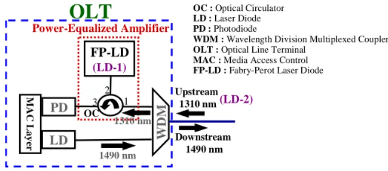
The proposed optical power equalizer is illustrated in Fig. 1. The equalizer consists of an optical circulator (OC) and a FL-LD connecting the receiver in OLT. The upstream signals from LD-2 will pass through the 1310/1490 nm WDM coupler and OC and into the proposed equalizer (LD-1) to equalize the power level. For convenience, in our experiment of the proposed architecture we used two 1.5 μm band FP lasers for the power equalizer (LD-1) and upstream signal source (LD-2) to replace the 1.3 μm band FP-LDs. Due to in 1.3 μm band without dispersion effects, thus we can directly adjust the power of 1.5 μm band FP-LD to simulate the different upstream power levels. Moreover, the mode spacing (Δλ) of the two FP-LDs used is nearly 1.28 nm, and their operating temperature is set at 22 oC. The threshold current (Ith) of LD-1 is ~9.5 mA. In this experiment, an operating bias current (Ib) of LD-1 is
set at 9 mA (Ib < Ith). Due to the gain competition or rearrangement characteristic of FP-LD
[6], the LD-1 can be used to keep the upstream power at a constant level. Because of the rate equation of semiconductor lasers [6], the LD-1 can operate below threshold current to lead to the absorption or amplification of the injection lightwave under different power levels.
WD M FP-LD (LD-1) Upstream 1310 nm
OLT
1490 nm PD LD 1 2 3 1310 nm Downstream 1490 nm M AC La y er Power-Equalized Amplifier OC OC : Optical Circulator LD : Laser Diode PD : PhotodiodeWDM : Wavelength Division Multiplexed Coupler OLT : Optical Line Terminal
MAC : Media Access Control FP-LD : Fabry-Perot Laser Diode
(LD-2)
Fig. 1. Proposed power equalizer in G-PONs to equalize the entire uplink power of each ONU. The equalizer is integrated in the OLT.
LD-of LD-1 when the different output powers from LD-2 are −8.5, −11.5, −13.5, and −15.5 dBm, respectively. In Fig. 4, the received output power (average power) versus different injection powers is shown for when the upstream signal injects into LD-1 at different power levels of
−1.5 to −25 dBm. Therefore, the received different output powers are distributed at −11 to
−15.3 dBm. From the results we observed that the larger injection power into the equalizer will be absorbed and the smaller injection will be amplified slightly. According to the G-PON standards, the maximum power variation from each ONU is nearly 20 dB. Furthermore, Fig. 4 also shows the maximum power variation of 1.7 dB at the injection power range of −5 to −25 dBm. Ibias = 9 mA Wavelength (nm) 1527 1532 1537 1542 1547 1552 1557 O u tput Pow er ( d B m ) -70 -60 -50 -40 -30 -20
Fig. 2. Output wavelength spectrum of 1.5 μm FP-LD at 9 mA bias current.
Pin = -8.5 dBm Wavelength (nm) 1537 1541 1545 1549 1553 1557 P o wer ( d B m ) -70 -60 -50 -40 -30 -20 Pin = -11.5 dBm Wavelength (nm) 1537 1541 1545 1549 1553 1557 P o wer ( d B m ) -70 -60 -50 -40 -30 -20 (a) (b) Pin = -13.5 dBm Wavelength (nm) 1537 1541 1545 1549 1553 1557 P o w er ( d B m ) -70 -60 -50 -40 -30 -20 Pin = -15.5 dBm Wavelength (nm) 1537 1541 1545 1549 1553 1557 P o w er ( d B m ) -70 -60 -50 -40 -30 -20 (c) (d)
Fig. 3. Output spectra of the LD-1 when the different average output powers from LD-2 are (a) −8.5, (b) −11.5, (c) −13.5, and (d) −15.5 dBm, respectively.
FP-LD : Ibias = 9 mA
Input Upstream Power (dBm) -30 -25 -20 -15 -10 -5 0 R ece ive d U p st re am Po w er ( d Bm ) -25 -20 -15 -10 -5
Fig. 4. Received average output power versus different upstream injection powers from −1.5 to −25 dBm when the upstream signal passes through the equalizer.
(a) (b)
(c) (d)
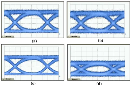
Fig. 5. Observed eye diagrams at the upstream powers of (a) −8.5, (b) −11.5, (c) −13.5, and (d) −15.5 dBm, respectively, modulated at 2.5 Gbit/s before passing through the proposed power equalizer.
In order to simulate each upstream signal with different power in the PON, a 1.5 μm upstream signal FP-LD (LD-2) is modulated by a 2.5 Gbit/s non-return-to-zero pseudo random binary sequence with a pattern length of 223–1 on a LiNbO3 electro-optical modulator.
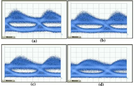
Four different upstream powers, which represent −8.5, −11.5, −13.5 and −15.5 dBm, respectively, are used to pass through the proposed equalizer. Figures 5(a) to 5(d) illustrate received eye diagrams of the given upstream powers before they have passed through the equalizer. The extinction ratios (ERs) of the four signals in total are larger than 8.5 dB. The different input signals, having passed through the equalizer, are again depicted with eye diagrams [see Figs. 6(a) to 6(d)]. The received powers also become −14.1, −14.5, −14.7, and
−14.9 dBm, respectively. The dimensions of eye opening in Figs. 6(a) to 6(d) are very similar and the four eye diagrams also have slight distortions. After passing through the equalizer, the four extinction ratios are measured to be larger than 7.1 dB, and in total they drop only ~1.4 dB. According to the report in [7], the response time of FP-LD was less than 1 ns. In other words, upstream signal processing is unaffected after the signal has gone through the proposed equalizer. Although the equalizer leads out the lower power level, the observed
slightly longer wavelength. In the experiments, the output multimode of the two FP-LDs used must correspond to each other. When the injection wavelength shifts over 0.08 nm, then the eye diagram upstream signal will become seriously distorted.
(a) (b)
(c) (d)
Fig. 6. Observed eye diagrams at the upstream powers of (a) −8.5, (b) −11.5, (c) −13.5, and (d) −15.5 dBm, respectively, modulated at 2.5 Gbit/s after passing through the proposed power equalizer. The four powers become −14.1, −14.5, −14.7, and −14.9 dBm, respectively.
3. Conclusion
We have first proposed and demonstrated experimentally the optical power equalizer for upstream traffic in a gigabit passive optical network based on a FP-LD. By the proposed equalizer, the dynamic upstream power range of 20 dB from −5 to −25 dBm with a 1.7 dB maximal power variation is guaranteed. Under a 2.5 Gbit/s modulation upstream traffic test, it was noted that all the upstream signals could be equalized without any effect on signal processing. Moreover, the performance of the proposed equalizer also has been discussed. Acknowledgment
This work was supported in part by the National Science Council (NSC) of Taiwan under grants NSC 95-2221-E-155-059 and NSC 95-2221-E-155-072.