國
立
交
通
大
學
資訊科學系
碩
士
論
文
記錄式快閃記憶體儲存系統之設計與實做
A Design and Implementation of Log Flash Storage System
研 究 生:李紀勳
指導教授:張瑞川 教授
記錄式快閃記憶體儲存系統之設計與實作
研究生:李紀勳
指導教授:張瑞川教授
國立交通大學資訊科學系
論
文
摘
要
快閃記憶體有許多吸引人的特徵,例如體積小,重量輕,不揮發性,耐撞性 和低耗電量。這些特徵使得快閃記憶體相當適合用在個人通訊設備還有嵌入式多 媒體系統上,如 MP3 撥放器和機上盒(Set-top box)。因為快閃記憶體在覆寫資 料前需要先抹除區塊。這個動作是相當耗時間跟能量的。除此之外,快閃記憶體 區塊的抹除次數有一定的限制。因此,要設計一個有效率,並以快閃記憶體為基 礎的儲存系統變得相當具有挑戰性。為了減少抹除快閃記憶體區塊的次數,前人 提出了許多資料管理的方法。但是這些方法當中,有些會產生區塊抹除次數不平 均的問題,另一些則需要很長的掛載時間。 因此,我們提出了一項新的快閃記憶體資料管理方法。它加了一塊隨機存取 記憶體(RAM)來當做快閃記憶體的延伸。除此之外,我們也提出了一個新的資料 群集方法(Dynamic data clustering with extra buffer region)來管理我們 快閃記憶體裡頭的資料。並且我們也設計新的資料擺放(Data layout)使得我 們的快閃記憶體儲存系統可以更有效率的執行。在我們的方法裡頭,經常性的資 料更新是在隨機存取記憶體中進行。因此抹除快閃記憶體區塊的次數便會減少。 實驗結果顯示,我們的方法可以減少 45%~95% 的抹除次數,也因而能延長快閃 記憶體的使用期。除此之外,我們也確保可以平均的抹除每一個快閃記憶體區塊。A Design and Implementation of
Log Flash Storage System
Student:Chi-Hsun
Li
Advisor:Prof. Ruei-Chuan Chang
Institute of Computer and Information Science
National Chiao Tung University
Abstract
Flash memory has many attractive features such as small, light weight, non-volatility, shock-resistant and low power consumption. These features are good for personal communication devices and embedded multimedia systems like MP3 player and set-top boxes. However, the erasing-before-overwriting characteristic of flash memory makes the design of flash-based storage systems become challenging. The erase operations are slow and energy-wasted. Moreover, the number of erase times is also limited. To reduce the number of erase operations and evenly wear flash memory, many data management approach were proposed. However, some of them have the uneven-wearing problem on data blocks, while others such as JFFS and JFFS2 need a long mounting time. Therefore, we propose a new data management approach for flash memory that uses an additional RAM buffer as the extension of the flash. Besides, we design a new data clustering method, Dynamic data clustering with Extra Buffer region (DEB), to manage the data in the flash memory. Besides, we design a new data layout for the flash memory to make our storage system more efficient. In our approach, hot data is usually updated in the RAM buffer in order to reduce the number of erase operations. Performance results show that the number of erase operations can be reduced by 45%~95%, flash memory lifetime is prolonged,
and even wearing is ensured.
Acknowledgement
I would like to thank my respected advisor, professor Chang, for instructing me in research and paper writing, and for providing the abundant resources for study and experiments. Additionally, I deeply appreciated Dr. David Chang’s assistance for giving me much advice and opinions on revising this thesis. Thanks to each member of the computer system laboratory for their encouragement and kindly help.
Besides, I was grateful to my family, which always gave me endless love and thoughtful support.
Computer System Laboratory CIS Department, NCTU, Taiwan
Chi-Hsun Li 2004/6/4
Index
論 文 摘 要 ...I
ABSTRACT... II ACKNOWLEDGEMENT...IV INDEX... V LIST OF FIGURES ...VI LIST OF TABLES ... VII
CHAPTER 1 INTRODUCTION ...1
1.1MOTIVATION...1
1.2THESIS ORGANIZATION...3
CHAPTER 2 BACKGROUND...4
2.1FLASH CHARACTERISTICS...4
2.2DATA UPDATE PROBLEM...5
2.3FLASH MEMORY CLEANING POLICIES...7
CHAPTER 3 RELATED WORK ...11
3.1 MEMORY TECHNOLOGY DEVICE (MTD)SUBSYSTEM FOR LINUX...11
3.2FLASH FILE SYSTEMS...12
3.3FLASH-MEMORY BASED STORAGE SYSTEMS...14
3.4CLEANING POLICIES...16
CHAPTER 4 DESIGN AND IMPLEMENTATION...18
4.1 DYNAMIC DATA CLUSTERING WITH EXTRA BUFFER REGION...19
4.2DATA LAYOUT ON FLASH...24
4.3CLEANING POLICY OF LFSS ...28
CHAPTER 5 EXPERIMENTAL RESULTS AND ANALYSIS ...30
5.1LFSSPERFORMANCE UNDER A FILE BENCHMARK...30
5.2EFFECT OF REFERENCE LOCALITY...32
5.3PERFORMANCE OF THREE CLEANING POLICIES...33
5.4EFFECT OF EBRSIZE...34
5.5EVEN WEARING...34
CHAPTER 6 CONCLUSIONS AND FUTURE WORKS ...36
6.1CONCLUSIONS...36
6.2FUTURE WORKS...37
List of Figures
Figure 2.1 Updating Data in Place ……….………..6
Figure 2.2 Non-in-place-update ……….………..7
Figure 2.3 Three Stages of Cleaning Process ……….………..8
Figure 3.1 MTD Subsystem ……….………..……..11
Figure 3.2 JFFS in the Linux File System Framework ……….12
Figure 3.3 Data Arrangement in JFFS ……….13
Figure 3.4 Page Remapping in eNVy (for a Write to Page 2) ……….15
Figure 4.1 LFSS in the Linux ……….19
Figure 4.2 Data Clustering in DAC ……….20
Figure 4.3 Stable Time Interval ……….21
Figure 4.4 Data Clustering in DEB ……….…………..……..22
Figure 4.5 Data Layout in JFFS ……….25
Figure 4.6 Data Layout in LFSS ……….27
Figure 5.1 Storage System Performance under Postmark ……….31
Figure 5.2 Effect of Varied Reference Localities ……….32
Figure 5.3 Performance under Different Size of EBR ……….34
List of Tables
Table 2.1 Flash Characteristics ……….….………..4 Table 4.1 Comparison of JFFS and LFSS ………..28 Table 5.1 Erase Times of Three Cleaning Policies ………..33
Chapter 1
Introduction
1.1 Motivation
Due to the small, lightweight, shock resistant, nonvolatile, and little power consumption, flash memory has been widely used for storing data in personal communication devices and embedded multimedia systems such as MP3 player and set-top boxes. However, some limitations of the flash memory have made it becomes challenging to design an efficient flash-based storage systems. One limitation is that the content cannot be overwritten directly. A data block needs to be erased before storing new data on it. Unfortunately, the erase operation usually takes about one second, which is too slow for current computing systems. In addition, it is energy-wasted. The other limitation is that the number of erase operations of a flash block is limited.
Because of the two hardware limitations, a flash memory based storage system should perform erasing as few as possible for prolonging the flash lifetime, improving the system performance, and reducing the power consumption. Besides, in order to avoid wearing out some specific blocks, erase operations must be balanced over the whole flash memory. This is called wear leveling or even wearing.
In order to reduce the number of erase operations and evenly wear flash memory, many data management approach were proposed. The DAC server [7] uses the data clustering method. And, it uses the non-in-place-update scheme for data updating to avoid per-update erasing. JFFS [9], similar to log-structured file systems [21], writes the data to flash memory sequentially. However, JFFS and JFFS2 need a long
mounting time, because their metadata is distributed over the total flash memory. In this thesis, we propose a new data management approach to overcome the flash hardware limitations. Based on the approach, we design and implement a flash memory storage system, LFSS (Log Flash Storage System). In order to reduce the number of erase operations, we use an additional battery-backed SDRAM buffer as the extension of the flash memory. Previous researches proved that separating data according to its access frequency can improve clean policies efficiency for flash memory. This technique is called data clustering. In this thesis, we design a new data clustering method, Dynamic data clustering with Extra Buffer region (DEB). It dynamically clusters data according to the data update frequencies. The data clustering is performed when segment cleaning and data updating. The basic idea of DEB is to make the hot data be updated in the SDRAM, instead of in the flash. Therefore, the erase operations can be reduced. Moreover, we propose a new data layout that separates the flash into two parts, super segments and data segments. During the system initialization, only the former needs to be scanned for building up the storage system, since it contains the metadata of the whole storage system. Besides, the real data is stored in the data segments sequentially. And, we implement three cleaning policies in the LFSS for segment cleaning.
According to the performance results, LFSS can reduce 45% ~ 95% erase operations when compared to other flash storage systems. And, with the increase of the RAM region size, more erase operations can be eliminated. Moreover, experiment results shows that LFSS is suitable for different cleaning policies, and it can evenly wear flash memory.
1.2 Thesis Organization
The rest of this thesis is organized as follows. Chapter 2 describes the background of the flash memory and cleaning process. Chapter 3 introduces related works. Chapter 4 describes the design and implementation of LFSS. Performance results are given in Chapter 5. And, Chapter 6 describes the conclusion and future work.
Chapter 2
Background
2.1 Flash Characteristics
Flash is a form of Electrically Erasable Read Only Memory (EEPROM), except that it is electrically erasable. It is available in two major types, which are the traditional NOR flash and the newer, cheaper NAND flash.
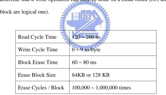
Flash chips are divided into blocks, whose sizes are typically 64KB or 128KB on NOR flash or 8KB on NAND flash. These two types of flash share a most important characteristic that a write operation can only be done on a clean block (i.e., all bits in this block are logical one).
Read Cycle Time 120 ~ 200 ns Write Cycle Time 6 ~ 9 us/byte Block Erase Time 60 ~ 80 ms Erase Block Size 64KB or 128 KB
Erase Cycles / Block 100,000 ~ 1,000,000 times
Table 2.1 NOR Flash Characteristics
Table 2.1 lists the typical NOR flash memory characteristics. The read cycle time is comparable to the time of a DRAM read operation (i.e., less than 200ns). However, writing a byte to a clean block needs about 6us. Moreover, writing to a non-cleaned block requires the erase operation to be performed first, which takes around 70ms. The lifetime of a block is measured in erase cycles, with a typical value of 100,000 to
1,000,000 erases. To balance the lifetime of all the blocks, most flash-based storage systems attempt to ensure that erase operations are evenly distributed around the whole flash chip. This is a well-known process named wear leveling or even wearing [12].
2.2 Data Update Problem
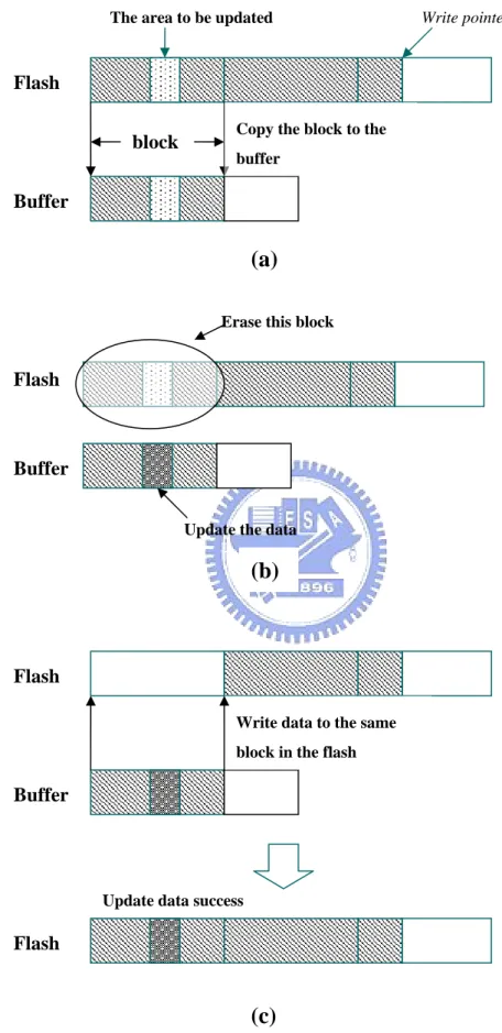
For flash memory, in-place update is not efficient since a block must be erased before being updated. Figure 2.1 shows the detailed operations for in-place update. In flash chips (e.g., 64 Kbytes or 128 Kbytes for Intel Series 2+ Flash Memory and 512 bytes for SanDisk flash memory), all data in the to-be-updated block must first be copied to a system buffer (a). Then, the data is updated in the buffer and the dirty block is erased (b). After the block has been erased, the block in the buffer is written back to the flash (c). It is worth to mention that even a one-byte update requires a block-read, a slow erase, and a block write operations. Therefore, in-place update results in poor performance. Moreover, in-place update violates the rule of even wearing. Hot data blocks will soon reach their erase cycle limits.
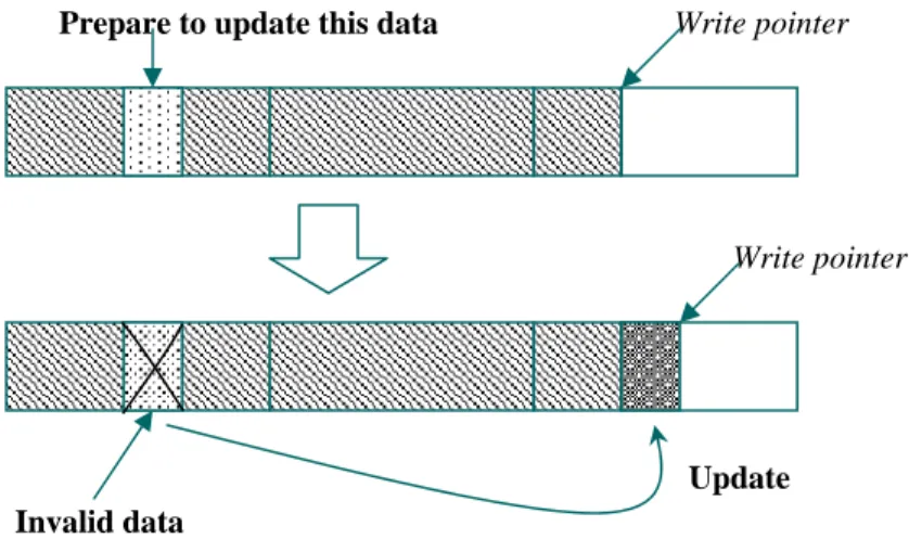
To avoid these problems, the non-in-place-update scheme was proposed. Figure 2.2 shows the detailed operations for non-in-place-update. Instead of updating data at the same address, new data is written to an empty space in the flash memory and the obsolete data is left as garbage. A software cleaner will be triggered later to reclaim these garbage by migrating the valid data from the block to be cleaned to another block, and then erasing the block. Therefore, the block will be available for storing new data.
Write pointer
The area to be updated
Figure 2.1 : Updating Data in Place Flash Buffer Flash Buffer Flash Buffer Flash
Copy the block to the buffer
Update the data Erase this block
(a)
(b)
Write data to the same block in the flash
Update data success block
Write pointer
Prepare to update this data
Figure 2.2 : Non-in-place-update
2.3 Flash Memory Cleaning Policies
2.3.1 Free Space Management : Segments
w data, the invalid data must be
s shown in Figure 2.3. First, as the Figure 2.3(a) illu
In order to get more free space for storing ne
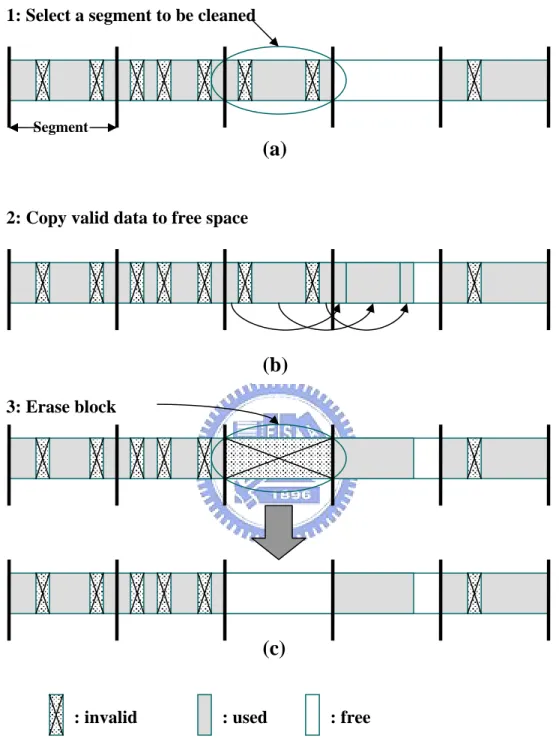
reclaimed. Many data management approach divides the flash memory into large, fix-sized segments for ease of reclaiming invalid data. A segment is made up of a number of contiguous blocks, where the number may be different for different data management approaches. When the number of free segments is less than a certain threshold, a software cleaning process (i.e., the cleaner) will be triggered to reclaim the invalid data.
2.3.2 Three-stage Operations of Cleaning Process
The cleaning of the invalid data involves three stages, a
strates, the cleaning process selects a victim segment and then identifies the valid data in it. In the next stage, shown in Figure 2.3(b), the valid data is copied into another free space. Finally, the victim segment is erased, as shown the Figure 2.3(c).
Invalid data
Update
Segment
: invalid : used : free
1: Select a segment to be cleaned
2: Copy valid data to free space
3: Erase block
(a)
(b)
(c)
Figure 2.3 : Th es of C g Process
2.3.3 Issues of Cleaning Policies
In this section, we describe four issues that must be addressed by a cleaning
ree Stag leanin
(1) When should the cleaner be triggered? One approach is to continuously run it as
(2) e? Segment cleaning
(3) as the segment selection
(4) try
.3.4 Segment Selection Algorithm
segment selection algorithms.
d is the simplest algorithm, which selects a segment with the large
2.3.4.2 Cost-Benefit Policy
[6] chooses to clean a segment that maximize the a low-priority task in the background. Another approach is to trigger it at night, or when disk space is nearly exhausted.
How many segments should the cleaner process at a tim
offers an opportunity to reorganize data on flash memory. In general, the more segments we clean at once, the more free space we get.
Which segments should be cleaned? This is referred to
algorithm. One may select a segment with the largest amount of garbage or
select segments based on their attributes, such as age, update times, and etc. How should the valid blocks be arranged when they are copied out? One may to enhance the locality by grouping files in the same directory into a single segment. Another possibility is to group the blocks with similar last-modified time into new segments. This can help cleaning policies executing more effectively.
2
In this section we shall introduce three
2.3.4.1 Greedy Policy
The greedy metho
st amount of garbage. According to the previous study [19], the greedy policy works well in the case of uniform access. However, it performs poorly under high locality of reference.
formula: u u age 2 ) 1 ( * −
, where 0< u≤1. U is the ratio of valid data in the segment, and therefore (1-u) stands for the amount of free space that can be reclaimed. The age indicates the time elapsed since the most recent modification (i.e., the last block invalidation or writing), and it is used to represent the hotness of the valid data. The
2u reflects the overheads of cleaning a segment (i.e., reading valid blocks and writing
them to another segment). Cost-benefit policy performs well under high locality of reference. However, it does not perform as well as the greedy policy under uniform access.
2.3.4.3 Cost Age Time (CAT) Policy
A similar policy to the previous one is the Cost Age Times (CAT) policy [5,6], which chooses to clean segments that minimize the following formula:
Cleaning Cost * Age
1
* Number of Cleaning.
The cleaning cost is defined as u/(1-u), where u is the percentage of valid data in a segment. The cleaning cost reflects the ratio of overheads to the benefit, which should be minimized. The definition of age is similar to cost-benefit policy. And, the
number of cleaning stands for the number of times a segment has been erased. The
basic idea of CAT is to minimize the cleaning costs, as well as gives the recently-cleaned segments more time to accumulate garbage for reclamation. In addition, to achieve the goal of wear-leveling, the segments with the fewest number of erases are given more chances to be selected for cleaning.
Chapter 3
Related Work
In this chapter, we will introduce four kinds of related work. Section 3.1 describes MTD subsystem, which is an interface layer between file systems and memory device drivers. Section 3.2 shows two well-known flash file systems, JFFS and MFFS. Section 3.3 introduces four flash-memory based storage systems that are related to our design. Section 3.4 describes cleaning policies used in the flash memory.
3.1 Memory Technology Device (MTD) Subsystem for
Linux
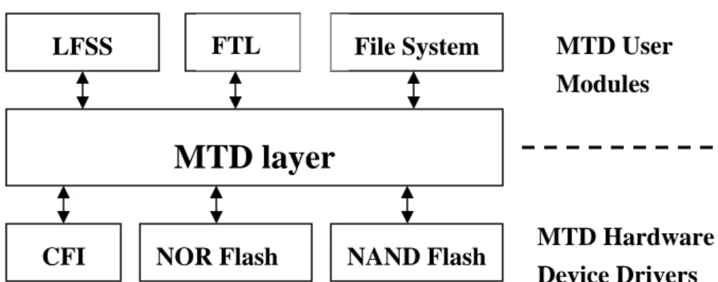
The Memory Technology Device (MTD) subsystem for Linux [8] provides a generic support for various types of memory devices, especially for Flash devices such as the M-Systems DiskOnChip and Common Flash Interface (CFI) onboard flash.
Figure 3.1 : MTD Subsystem
MTD layer
CFI NOR Flash NAND Flash
File System FTL MTD User Modules LFSS MTD Hardware Device Drivers
The aim of this subsystem is to provide a generic interface between the hardware drivers and the upper layers of the system. Hardware drivers only need to supply simple routines such as reading, writing, erasing, and querying for the device. Data presentation of the device is handled by the upper layer components, such as FTL (Flash Translation Layer) and JFFS2, which are called MTD user modules (as shown in Figure 3.1). From the figure we can see that, LFSS is also implemented as a MTD user module.
3.2 Flash File Systems
3.2.1 JFFS
Application Application Application
Figure 3.2 : JFFS in the Linux File System Framework
Hardware JFFS
Virtual File System
Ext3 Shared library User space Ext2 FAT Buffer Cache Disk Driver MTD Flash Driver Kernel space
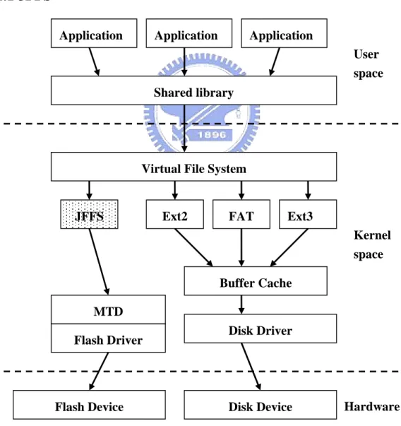
JFFS is a ns AB in Swe
anges a flash device as a circular area, as shown in Figure 3.3. Mod
log-structured file system designed by Axis Communicatio
den. It is especially used for flash devices on embedded systems. Figure 3.2 shows how JFFS fits into the file system framework in Linux. From the figure we can see that, JFFS sits between the VFS and the MTD layers. In addition, a major difference between JFFS and ordinary file systems is that the former does not rely on buffer cache.
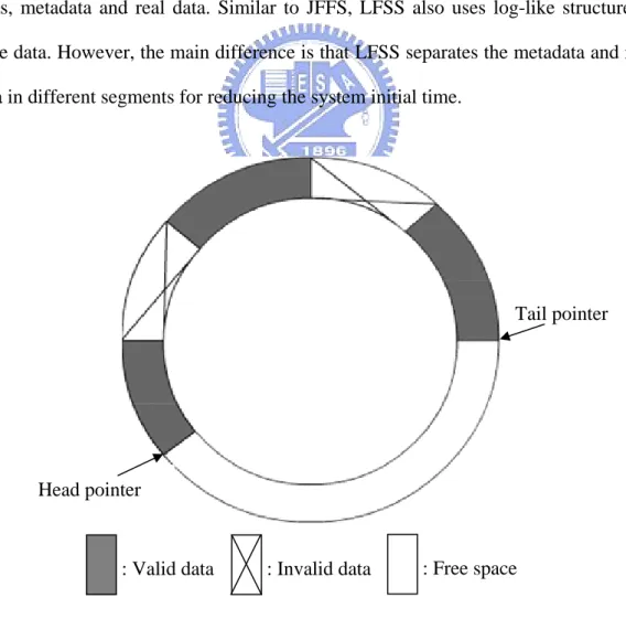
JFFS arr
ifications to the file system are written at the tail (i.e., the start of the free chunks). Invalid data blocks are reclaimed from the head. The basic data structure used for storing data on the flash device is the raw node. Each raw node is divided into two parts, metadata and real data. Similar to JFFS, LFSS also uses log-like structure to store data. However, the main difference is that LFSS separates the metadata and real data in different segments for reducing the system initial time.
Head pointer
Tail pointer
Figure 3.3 : Data Arrangement in JFFS
3.2.2 Microsoft Fl
provides complete file system capa
3.3 Flash-Memory Based Storage Systems
orage systems.
3.3.1
flash memory and mana
ng to their write access frequencies and dyna
3.3.2 eNVy
] is a large flash memory-based storage system, which provides a mem
ash File System (MFFS)
Microsoft Flash File System (MFFS) [23]
bilities for DOS. It uses linked lists to store and manage data in flash memory. Data are allocated as variable-sized regions instead of fix-sized blocks. And, the greedy policy is used for reclaiming invalid data. Previous research [13] reported that MFFS performs poor when accessing large files. Specifically, its write performance degrades linearly with the growth of file size.
In this section, we introduce four flash-memory based st
Dynamic Data Clustering Server (DAC Server)
DAC server [5] uses the DAC approach to cluster data on
ges flash memory as fix-sized blocks and uses the non-in-place-update scheme for data blocks to avoid per-update erasing.
DAC server is to classify data accordi
mic cluster them at the time when the data is updated or when the segments are cleaned. However, DAC approach is not suitable for our environment that has an additional battery-backed SDRAM buffer.
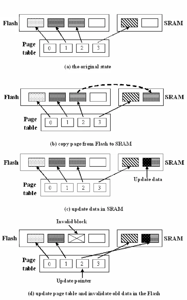
eNVy [26
ory interface rather than a block-based disk interface. The hardware consists of the flash memory, a small battery-backed SRAM for write-buffering, a high-bandwidth parallel data path between them, and a controller for page mapping and cleaning. Figure 3.4 shows the page-remapping technique of eNVy.
Figure 3.4 : Page Remapping in eNVy (for a Write to Page 2)
Flash
Data o prevent upda
3.3.3 Flash Translation Layer (FTL)
sh memory to emulate a hard disk. Basi
3.3.4 Large-Scale Flash Memory Storage System
scheme for large-scale ash
3.4 Cleaning Policies
important issue in flash storage systems. Rosenblum update is performed with the help of page-remapping in order t
te in place. It uses a hybrid cleaning policy that combines FIFO and locality gathering to minimize the cleaning costs for uniform access and high locality of reference. Simulation results show that it can handle 30,000 transactions per second at a flash utilization of 80%. Similar to eNVy, our design also uses a small battery-backed SRAM. However, LFSS uses DEB data clustering approach to make hotness data always be updated in SDRAM. Besides, CAT cleaning policy is used in LFSS. Therefore, LFSS can reduce more erase operations and even wearing.
M-Systems’s TrueFFS [10] allows fla
cally, it is a software block device driver to be used with an existing file system. Flash memory is divided into fixed-sized blocks. The data presentation, which is patented by M-Systems, is called Flash Translation Layer (FTL) standard. And, some researches [24,25]implement over the flash translation layer for the compatibility of their applications and systems.
Chang, et al. [3], proposed to a flexible management
fl -memory storage systems. It efficiently manages high-capacity flash-memory storage systems based on the behaviors of realistic access patterns. Besides, it uses the real time garbage collection mechanism [4] to manage its invalid data. Therefore, their proposed scheme could significantly reduce the main-memory usages without noticeable performance degradation.
and
ich we mentioned in Section 2.3.4.3, prov
es the greedy policy for clean
Ousterhout [21] suggested that the Log-structured File System (LFS), which writes data as appended log instead of updating data in place, can be applied to flash memory. In the paper, the authors showed that the greedy policy performs poorly under high localities of reference. Therefore, the cost-benefit policy was proposed. As we mentioned in Section 2.3.4.2, it tries to clean segments with cold data. As a result, it performs well under high locality of reference.
The Cost Age Times (CAT) [5,6] policy, wh
ides better wear leveling than the cost-benefit policies because the number of erase operations performed on each segment is considered.
Linux PCMCIA [11] flash memory driver also us
ing. However, to avoid concentrating erasures on a few segments, it sometimes chooses to clean the segment that has been erased the fewest number of times. This is called revised greedy policy.
Chapter 4
Design and Implementation
In this chapter, we describe the design and implementation of the Log Flash Storage System (LFSS). LFSS uses an additional battery-backed SDRAM buffer as the extension of the flash memory. Moreover, it integrates two techniques that we propose for improving the performance of the SDRAM-embedded flash memory system. The first technique is a data clustering method, Dynamic data clustering with Extra Buffer region (DEB). It makes the hot data to be updated in the extra RAM buffer so as to reduce the erasing times of flash blocks. The second technique is a data layout approach that separates the flash memory into two parts, super segments and data segments. Super segments contain a number of checkpoint nodes, each of which holds the total metadata in the flash. Therefore, we can simply scan the super segments, instead of the total flash memory, during the system initialization. As a result, LFSS can reduce the initialization time. The real data is stored in data segments sequentially, and LFSS manages flash memory as variable-sized blocks like as log-structured file systems. The non-in-place-update scheme is used when data blocks are updated.
In addition to the two techniques, we also implement three cleaning policies in LFSS in order to evaluate the cleaning effectiveness.
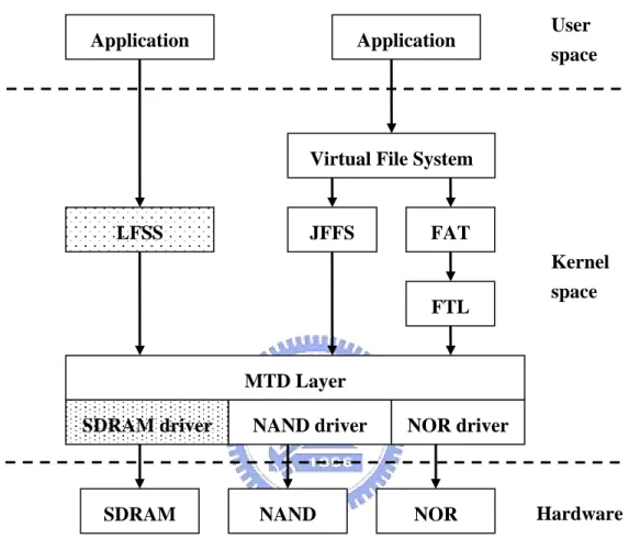
The system is implemented in Linux 2.4.20. Different from JFFS that provides an interface to the virtual file system, LFSS provides its interface directly to user space. As Figure 4.1 is shown, LFSS is implemented as a MTD user module. It provides functions such as read, write, erase, and update to application programs. For ease of experiment in the PC environment, we use SDRAM, instead of flash, for
performance evaluation. Therefore, we implement a SDRAM MTD driver to connect the MTD layer. All MTD user modules regard the SDRAM MTD driver as a normal flash.
User space
Figure 4.1 : LFSS in the Linux
The rest of this chapter is organized as follows. We first describe the DEB data clustering approach in Sec
4.1 Dynamic Data Clustering with Extra Buffer Region
When a segment is selected to be cleaned, the valid data in it should be migrated to anothe
tion 4.1. Section 4.2 introduces the flash data layout of LFSS. The cleaning policy we implemented in LFSS is represented in Section 4.3.
r segment. If the system migrates the valid data to a segment that will be cleaned soon, the migration becomes useless and wasteful. Therefore, the data
Virtual File System
LFSS JFFS FAT MTD Layer SDRAM Kernel space FTL Application Application NAND NOR
SDRAM driver NAND driver NOR driver
reorganization is important to flash-memory based storage systems. Previous research [6,17,21,24] about data reorganization pointed out that separating hot data from cold data can reduce cleaning overhead. Hot data stands for the data that is updated frequently. On the contrary, cold data is stable.
DAC (Dynamically dAta Clustering) approach [5] dynamically clusters data durin
ure 4.2 : D tering in D
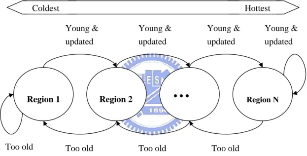
DAC partitions the flash memory into several logical regions that contain data with
g segment cleaning and data updating. Therefore, the hot data and cold data can be separated by migrating them to different flash memory spaces.
Fig ata Clus AC
different degrees of hotness. Each region includes a set of flash segments, which are not needed to be physically contiguous. The basic idea of DAC is to cluster data segments with similar write access frequencies in the same region. Because data access frequencies may change over time, a data segment will be migrated among regions when its write access frequency changes. Figure 4.2 shows that if the update frequency increases, the data will be moved toward the hottest region. And, it will be moved toward the coldest region if the update frequency decreases. Besides, when a
Too old
Region 1 Region 2
…
Region NYoung & Young & Young & updated updated updated
Too old Too old
Young & updated
Coldest Hottest
segment is selected for cleaning, all of its valid old data will be moved to the free space in the next colder region. Therefore, the DAC approach is more fine-grained and more effective in data clustering than other research that just separates data into two classes, hot and cold.
On the basis of adding a SDRAM buffer as the extension of the flash, we prop
the second data clustering policy, DEB (Dynamically data clust
regio
ose two policies. First, we make the SDRAM to be the hottest region in DAC approach. Because the hottest data will be updated in SDRAM, we can reduce a lot of erase operation. However, this is not aggressive and effective. This is because the hottest data must be moved through total region to reach the hottest region. Moreover, some hotter data may be not reach the hottest region, because it is not hot enough to move through total region.
Therefore, we propose
ering with Extra Buffer region). The basic idea is to make hot data be updated in SDRAM, instead of the flash memory so as to reduce the number of erase operations.
Similar to DAC, DEB also partitions the flash memory into several logical ns. And, we always associate the extra RAM buffer to the Extra Buffer Region (EBR). As we mentioned before, each region contains a set of segments, which are not to be physically contiguous. Thus, each segment is associated with a single region at any given time.
Each flash region has a corresponding stable time interval, as shown in Figure 4.3 i
Figure 4.4 : Data Clustering in DEB
s shown, which defines the range of the appropriate stable time1 for the data in the region. Assuming that sst(n) represents the shortest stable time and lst(n) represents the longest stable time of the interval belonging to region n. From the figure we can see that, the value of sst(i) is equal to the value of lst(i+1). And, both sst and lstof a colder region are bigger than the corresponding values of a higher region. It is because the data in the former is more stable.
f1 f1 f1 w f2 w f2 f2 w w
( First fast updated ) ( Second fast updated )
( Write back to region from EBR ) ( slow update )
f1 :
f2 :
w :
s :
Region 1 Region 2
…
RegionEBR
N
Coldest
Hottest
1
Basically, an update involves two entities, the block and the region that the block associate order to simplify the description, we say an update is fast if the time between the update and the last update of the block (i.e., the stable time of the block) is less than the sst value of the region. Similarly, an update is said to be slow if the t ore than value of gion. Figu ws the data reorganization diagram in DEB. The data reorganization happens when data blocks are updated or when segment cleaning occurs. The rules of the data reorganization can be summarized as follow
1. Newly created data blocks are placed in the RAM buffer, and thus they are associated with EBR.
2. If a data block is to be updated and its stable time falls in the interval of the current region, the new data is written to the free space of the current region.
f a fast , we check the last update of this block. If he last u is written to the free space of the next hotter region (denoted as f1 in Figure 4.4). Otherwise, the new data is written to the free space in the EBR (denote as f2 in Figure 4.4). After writing the new data, the obsolete data s
ata means that the time elapsed since the last update s with. In
the lst
ime is m the re re 4.4 sho
s :
And, the obsolete data block is invalidated as garbage.
3. I update happens on a block
t pdate was not a fast one, the new data
block in the original region i invalidated as garbage.
4. If a slow update happens on a block, the new data is written to the free space of the next colder region (denoted as s in Figure 4.4). And, the obsolete data block in the original region is invalidated as garbage.
5. If the used space in the EBR is greater than a certain threshold, we write back the oldest data in it to the suitable region until the used space in the EBR is lower than the half of threshold (denoted as w in Figure 4.4). The suitable region for the d
of the data falls in the stable time interval of that region. If a data block update
6. happens in the EBR, the block is updated in place.
in the same region.
data duri frequenci Besi erased too
executed. ent will move to the hotter region if the erase times of th eg We advantage ustering. Seco it in the EB because S
4.2 Dat
with our design. In Section 4.2.1, we in describe LFSS in Section 4.2.2.
4.2.1 Data Layout in JFFS
7. When a segment is selected for cleaning, all valid data blocks in it are copied to the free space of the next colder region. This is because valid data in the selected segment is usually colder than other data
From the above rules we can see that, EBR gathers the most frequently updated ng the recent accesses. And, the data blocks of similar write access es can be clustered.
des data clustering, we also consider even-wearing in DEB. If a segment is many times, it will be move to the colder region when cleaning process is At the same time, a segm
is s ment are few.
can summarize the advantage of DEB as follows. First, it inherits all the s of DAC, such as fine-grained, effective, and low-overhead data cl
nd, reduces the number of erase operations on a flash, since the data is updated R for the most part. Moreover, the data updating is even more effective, DRAM has lower write access time than flash memory.
a Layout on Flash
In this section, we shall describe the data layout of LFSS, and compare JFFS troduce the data layout in JFFS. Then, we
the f
is performed to a file or directory, a new raw node (with the new
lash memory, raw node and invalid node. The basic data structure used when storing data on the flash device is the jffs_raw_inode structure. Basically, a raw node belongs to a file. It contains both the metadata of the file and a part of the file data. Each time a modification
data) is written. Therefore, the metadata of the total raw nodes contains all the information needed to build the file system. However, distributing metadata over the flash makes JFFS perform poorly in mounting. This is because JFFS needs to scan all the blocks in the flash to build the system. Invalid nodes will be erased by cleaning process.
Invalid node
Raw node Free space
Raw node
…
Raw node
Jffs_raw_inode
Figure 4.5 : Data Layout in JFFS File Name or
Directory Name
Magic number Inode number Version number Last access time Data size
…
Checksum DATA
4.2.2 Data Layout in LFSS
Figure 4.6 shows the data layout in LFSS. From the figure we can see that LFSS
divides flash into m d se se two
groups, super segments and data segments.
Most of the segments are data segments, which are responsible for storing real data. Previous research reported that log-structured is more suitable for flash memory. Therefore, LFSS uses the log-structured to store data se der to avoid performing erase op update.
The others are super segments, which locate at the beg ing of the flash. The basic data structure in each super segment is checkpoint node
contains the m e whole storage system super segments only, instead of scanning the total flash memory, to find the most up-to-date checkpoint node for building the storage system during the sy itialization. This reduces the initialization time. Each checkpoint node records the following information :
z Magic number
The value of the magic number is 0xEECC2299. It is used for identifying a checkpoint node.
ment information block to describe any fix-sized segments an parates the gments into
quentially in or erations for each
inn
. Each checkpoint node etadata for th . Therefore, we can scan
stem in
z Used segments
This value indicates the number of used segments. A used segment represents a segment that contains data in it.
z Update time
The last update time of the checkpoint node is stored in this field. It can be used for LFSS to find the most up-to-date checkpoint node.
z Segment information block
segment-wide information such as the number of times the segment has been erased, the region number, an array of data information block, and etc. The region number indicates the region that this segment belongs to. The last erase timestamp records when the last erase operation happened on this segment. The free and dirty spaces represent how much free space and invalid space in this segment, respectively. The used data block stands for that the number of data blocks in this segment. And, the array of data
blocks contains the information of every block in the segment, information
such as update time, data size, and etc.
Figure 4.6 : Data Layout in LFSS
Node no. Update time Data size Name
…
segment segment…
Data segments
Super segments
Magic num.(0xEECC2299) Used segments Update time Segmen segment Region number No. of erase operation Last erase timestamp Free spaceDirty space Used data block Data information block
Data information block t information block
Segment information block
…
…
Che
nod
ckpoint
e
Whe kpoint node needs to be updated. However, this does not cause the uneven-wearing problem since LFSS makes the checkpoint nodes always be updated in the EBR. In addition, updating checkpoint nodes in EBR also eliminates a large number of erase operations and hence prolongs the flash lifetime. The checkpoint node is written back to flash periodically or when the system shuts do rre entation the write back in 0 seconds.
is chapter, we summarize the comparison of JFFS and LFSS in Table 4.1.
JFFS LFSS
n a data block is updated, the chec
wn. In cu nt implem terval is 3
From the description in th
System Initialization Scanning total flash Scanning a few of blocks
Storing Type Log Log
Clusterin A g pproach No use DEB Metadata Location Distributed over the flash m
Distributed over the ents emory super segm
Table 4.1 Comparison of JFFS and LFSS
cleaner selects the segment with the largest amount of invalid data for
4.3 Cleaning Policy of LFSS
In order to show that DEB data clustering is effective for reducing the cleaning costs under various cleaning policies, we implement the following three segment cleaning algorithms.
I. Greedy Policy
The cleaning.
II. Cost-Benefit Policy
The cleaner chooses to clean segments that maximize the formula:
u
2
u age*(1− )
, where 0< u≤1.
Th memo zation and age ime since the most recent mo
III. C
T oses to at :
e u is the flash ry utili is the t dification.
AT Policy
he cleaner cho clean segments th minimize the formula
t u * , where 0 age u *) 1 ( − < u≤1.
The u and age is the similar with the cost-benefit policy, and t is the number of times the segment has been erased.
Chapter 5
Experimental Results and Analysis
LFSS is implemented as a MTD user module in Linux 2.4.20. For ease of experiment in PC environment, we use SDRAM, instead of the flash memory, for performance evaluation. Therefore, we implement the SDRAM MTD driver to connect the MTD layer. And, it can record the number of erase operations of each segments. Note that using SDRAM for experiment does not affect the results since they are reported in number of erase operations. All measurements were performed on a machine with 2.0 GHz Pentium 4 and 256 Mbytes DDRAM. Since the cleaning overhead does not significantly affect performance at low flash utilization [6], we filled 90% of flash memory space before we did the experiments. Besides, we divide the flash into 4 regions in all experiments. And, the stable time intervals are 100, 200, 300, 400 seconds, respectively. The DAC with 4Mb in figures means our first policy, which uses SDRAM to be the hottest region.
The following sections show the experimental results. Section 5.1 presents the performance of LFSS under a file benchmark, Postmark. LFSS outperforms the other storage systems when the locality of reference increases, as shown in Section 5.2. Section 5.3 shows that LFSS performs well in various cleaning policies. Section 5.4 presents the effect of EBR size on the system performance. Finally, Section 5.5 shows that LFSS ensures even wearing.
5.1 LFSS Performance under a File Benchmark
compare its perfor
4MBytes under a file benchmark, Postmark [16]. PostMark is configured to create a number of file initially. During the experiment, it performs transa
mance with those of JFFS, DAC server, and DAC server with
ctions such as read, pend, create, and delete to those files randomly, and report the transaction rate as the r
ap
esult. Since we are interested in the number of erase operations performed during the experiment, we get this information from the SDRAM MTD diver. Because LFSS does not locate under the VFS layer, we modify the source code of postmark for connecting it to LFSS read, write interface. Figure 5.1 shows the performance results. The size of EBR is 4Mbytes and the flash size is 64 Mbytes. Moreover, the flash initial utilization is 90%. From the figure we can see that, the performance of LFSS is better than JFFS and DAC server. The performance difference between LFSS and DAC server with 4Mbytes is little, but the former still performs better than the latter. It is because DEB approach can move the hotter data to SDRAM efficient.
0
500
1000
1500
2000
2500
Num ber f er ase o p ation3000
o er s2000
3000
4000
5000
6000
Number of transactions JFFS DAC DAC (4MB) LFSS (4MB) tmark Figure 5.1 : Storage System Performance under Pos5.2 Effect of Reference Locality
In this experiment, we measure the performance of LFSS under different degrees of reference locality. We use notation y/x for representing locality of reference, which means that x% of the accesses are referencing to y% of the data. In this experiment, the total flash size is 64Mbytes, the EBR size is 4Mbytes, and 40Mbytes of data is updated. Besides, we use the CAT cleaning policy. Finally, we take the results of the DAC server as a comparison.
We implement a test program, which provides two parameters, initial size and reference locality. Initial size means the test program creates a number of files, which total size is it. The reference locality is the same with the above mention.
0
1000
2000
3000
4000
5000
Nu m ber o f er ase op er at io ns 50/50 40/60 30/70 20/80 10/90 Locality of Referance LFSS (4MB) DAC (4MB)DAC
Figure 5.2 : Effect of Varied Reference Localities
Figure 5.2 ies. As
the reference locality increases, the reduction of the erase operations grows. Specially shows the performance results under varied reference localit
the LFSS outperforms DAC server and DAC server with 4Mbtes by 40% and 23% under the 50/50 locality of reference, re
er outperforms the latter under uniform access and high locality of reference.
In order to prove that LFSS is not restricted to a specific cleaning policy, we measure its performance under three cleaning policies mentioned in Section 4.3. In the experiment, we update 40Mbytes of data. The flash size is 64 Mbytes and flash utilization is 90%. We use the test program, which is mentioned in 5.2, under 10/90 locality of reference.
Table 5.1 shows the performance results. From the table we can see that, LFSS outperforms LFSS without EBR under all of the three cleaning policies. Specifically, about 93% of erase operations were eliminated for greedy policy, 91% for Cost-Benefit policy, and 82% for CAT policy.
LFSS (No EBR) LFSS (4Mbtes) Improvement
spectively. Under the 10/90 locality of reference, however, LFSS and DAC server with 4Mbytes eliminate 88% of erase operations. This is because hottest data in LFSS and DAC server with 4Mbytes are both always updated in the SDRAM under high locality of reference. Therefore, we can see that LFSS performs the same with DAC server with 4Mbytes under very high locality of reference, and the form
5.3 Performance of Three Cleaning Policies
Greedy 7818 548 93%
Cost-Benefit 4898 417 91%
CAT 1972 368 82%
5.4 Effect of EBR Size
Figure 5.3 shows the performance of LFSS under different sizes of EBR. The value of the zero-sized EBR represents the performance of LFSS without EBR, which is used for comparison. Besides, we also show the number of erase operations under the three cleaning policies. The test program and flash initialization are all the same with Section 5.2. 0 1000 2000 3000 5000 0 1 2 3 4 Num b s 4000 8000 9000
EBR Size (Mbytes)
er of era
ions
6000 7000
e operat
Greedy Cost-benefit CAT
es. The LFSS with 4Mbytes of BER outperforms by 88% to 95%. This is because the bigger the EBR is, the more hot data can be updated in it. And therefore, more eras rations can be
5.5 Even Wea
Since even wearing is an important goal for flash-based storage systems, we verify in this experiment that LFSS can achieve the goal. We use a 64Mbytes flash
Figure 5.3 : Performance under Different Size of EBR
As the figure shows, LFSS eliminates more erase operations under all the three cleaning policies when the size of EBR increas
e ope eliminated.
with 1Mbyte segments. And, CAT cleaning policy is used in this experiment. The result is measured by running the postmark file benchmark for 100000 transactions.
Figure 5.4 shows the number of erase operations on each segment. From the figure we can see that, the numbers of erase operations on segments are similar with each other. The numbers are between 180 and 220. Therefore, LFSS ensures even wearing. 150 180 210 240 0 16 32 48 Segment number nu m be r of e ras e o pe ra tio ns 64
Chapter 6
Conclusions and Future Works
e describe the design and implementation of Log Flash Storage System (LFSS) for the flash memory. Because of the flash limitations, a flash memory based storage system should perform erasing as few as possible for prolonging the flash lifetime, improving the system performance, and reducing the power consumption. LFSS use an additional RAM buffer as the extra buffer region of flash memory to reduce the number of erase operations. And, it has the DEB data reorganization technique for clustering data with the similar updating frequency.
Moreover, we propose a new data layout for the flash memory. It separates the flash memory into two nts. During the system initialization, only the former needs to be scanned for building up the storage system, since it contains the metadata of the whole storage system. As a result, LFSS can reduce the initial time. And, LFSS uses the non-in-place-update approach to avoid erasing blocks during every updating, there are three cleaning policies, greedy, cost-benefit, and CAT are implemented in the LFSS.
Performance evaluation shows that with CAT policy and DEB data clustering, LFSS not only reduces a large amount of erase operations, but also evenly wears flash memory. Under uniform access, LFSS with CAT cleaning policy outperforms DAC server by 40% and DAC server with 4MBytes by 23% in reducing the number of erase operations. Moreover, with the increase of the extra buffer size, the erase operations can be reduced more. Finally, the experiment shows that LFSS is suitable
6.1 Conclusions
In this thesis w
for different cleaning policies.
6.2 Future Works
In order to make application program easy to use LFSS, we will implement the . This allows LFSS to be placed under VFS layer in Linux, so that
VFS interface for LFSS
application programs can use LFSS through ordinary file related system calls. After the implementation, we can analyze performance under a more diverse set of real workloads and real applications without modifying their source code to suit LFSS interface.
Reference
[1] D. Anderson, PCMCIA System Architecture, MindShare, Inc. Publishing Company, 1995.
Addison-Wesley
[2] T. Blackwell, J. Harris, M. Seltzer, “Heuristic Cleaning Algorithms in Log-Structured File Systems”, in Proceedings of the 1995 USENIX
Technical Conference, pp. 277-288, New Orleans, LA, Jan, 1995.
[3] Li-Pin Chang and Tei-Wei Kuo, “An Efficient Management Scheme for Large-Scale Flash-Memory Storage Systems,” in Proceedings of ACM
Symposium on Applied Computing, pp. 862-868, Nicosia, Cyprus, March
2004.
[4] Li-Pin Chang and Tei-Wei Kuo, "A Real-Time Garbage Collection Mechanism for Flash-Memory Storage Systems in Embedded Systems," in
proceedings of the Eighth International Conference on Real-Time Computing systems and Applications, Tokyo, Japan, March 2002.
[5] M. L. Chiang, Paul C. H. Lee, and R. C. Chang, “Managing Flash Memory in Personal Communication Devices”, in Proceedings of the 1997
International Symposium on Consumer Electronics (ISCE’97), pp. 177-182,
Singapore, Dec. 1997.
[6] M. L. Chiang and R. C. Chang, “Cleaning Policies in Mobile Computers Using Flash Memory”, Journal of Systems and Software, Vol. 48, No. 3, pp. 213-231, 1999.
[7] M. L. Chiang, Paul C. H. Lee, and R. C. Chang, “Using Data Clustering to Improve Cleaning Performance for Flash Memory,” Software Practice & Experience, Vol. 29, No.3, pp. 267-290, Mar. 1999.
[8] David Woodhouse, “Memory Technology Device (MTD) subsystem for Linux”, available at http://www.linux-mtd.infradead.org/
http://sources.redhat.com/jffs2/jffs2-html/jffs2-html.html
[10] R. Dan and J. Williams, “A TrueFFS and Flite Technical Overview of
M-Systems Flash File Systems”, 80-SR-002-00-6L Rev. 1.30. available at
[11]
[12] [13]
Alternatives for Mobile Computers”, in Proceedings of the First
[14] ment for
[15]
[16] ark: A New File System Benchmark”, available at
[17]
ceedings of the 1995 USENIX Technical Conference, pp.
[18]
Hawaii International
[19] Wang, and T. E.
http://www.m-sys.com/tech1.htm, March 1997.
W. de Jonge, M. F. Kaashoek, and W. C. Hsieh, “The Logical Disk: A New Approach to Improving File Systems”, in Proceedings of 14th Symposium
on Operating Systems Principles, pp. 15-28, 1993.
B. Dipert and M. Levy, Designing with Flash Memory, Annabooks, 1993. F. Douglis, R. Caceres, F. Kaashoek, K. Li, B. Marsh, and J. A. Tauber, “Storage
Symposium on Operating Systems Design and Implementation (OSDI), pp.
25-37, 1994.
Han-joon Kim , Sang-goo Lee, “A New Flash Memory Manage
Flash Storage System”, in Proceedings of the 23rd International Computer
Software and Applications Conference, pp. 284-293, Oct, 1999.
Intel, Flash Memory, 1994. Jeffrey Katcher, “PostM
http://www.netapp.com/tech_library/3022.html
A. Kawaguchi, S. Nishioka, and H. Motoda, “A Flash-Memory Based File System”, in Pro
155-164, Jan. 1995.
B. Marsh, F. Douglis, and P. Krishnan, “Flash Memory File Caching for Mobile Computers”, in Proceedings of the 27
Conference on System Sciences, pp. 451-460, Maui, HI, 1994.
J. N. Matthews, D. Roselli, A. M. Costello, R. Y.
with Adaptive Methods”, in Proceedings of the Sixteenth ACM Symposium
[20] A Pageable Memory Based
[21] and Implementation of a
l.
[22]
f the 1993 Winter USENIX, pp. 307-326, 1993.
[24] ent B-Tree
torage Systems,” in Proceedings of the 9th
ROC, Feb 2003.
on Operating System Principles, Saint Malo, pp. 238-251, France, Oct,
1997.
M. K. McKusick, M. J. Karels, and K. Bostic, “
File System”, in USENIX Conference Proceedings, pp. 137-144, Anaheim, CA, Summer 1990.
M. Rosenblum and J. K. Ousterhout, “The Design
Log-Structured File System”, ACM Transactions on Computer Systems, Vo 10, No. 1, pp. 26-52, 1992.
M. Seltzer, K. Bostic, M. K. McKusick, and C. Staelin, “An Implementation of a Log-Structured File System for UNIX”, in
Proceedings o
[23] P. Torelli, “The Microsoft Flash File System”, Dr. Dobb’s Journal, pp. 62-72, February 1995.
Chin-Hsien Wu, Li-Pin Chang, and Tei-Wei Kuo, “An Effici Layer for Flash-Memory S
International Conference on Real-Time and Embedded Computing Systems and Applications, pp. 409-430, Tainan, Taiwan,
[25] Chin-Hsien Wu, Li-Pin Chang, and Tei-Wei Kuo, “An Efficient R-Tree Implementation over Flash-Memory Storage Systems,” in Proceedings of
the ACM 11th International Symposium on Advances on Geographic
[26]
onference on Information Systems, pp. 17-24, New Orleans, Louisiana, USA, Nov 2003.
M. Wu and W. Zwaenepoel, “eNVy: A Non-Volatile, Main Memory Storage System”, in Proceedings of the Sixth International C
Architectural Support for Programming Languages and Operating Systems,