國
立
交
通
大
學
網路工程研究所
碩
碩
碩
碩
士
士
士
士
論
論
論
論
文
文
文
文
IP 多媒體系統過渡閘道之 IPv4-IPv6 轉換效能分析
A Performance Study for IPv4-IPv6 Translation
on Transition Gateway in IP Multimedia Subsystem
研 究 生:林品任
指導教授:林一平 教授
陳懷恩 教授
中
中
中
中
華
華
華
華
民
民
民
民
國
國
國
國
九
九
九
九
十
十
十
十
七
七
七
七
年
年
年
年
七
七
七
七
月
月
月
月
IP 多媒體系統過渡閘道之 IPv4-IPv6 轉換效能分析
A Performance Study for IPv4-IPv6 Translation
on Transition Gateway in IP Multimedia Subsystem
研 究 生:林品任 Student:Pin-Jen Lin
指導教授:林一平 Advisors:Yi-Bing Lin
陳懷恩 Whai-En Chen
國 立 交 通 大 學
網 路 工 程 研 究 所
碩 士 論 文
A ThesisSubmitted to Institute of Network Engineering College of Computer Science
National Chiao Tung University in partial Fulfillment of the Requirements
for the Degree of Master
in
Computer Science July 2008
Hsinchu, Taiwan, Republic of China
IP 多媒體系統過渡閘道之 IPv4-IPv6 轉換效能分析
學生:林品任 指導教授:林一平 教授
陳懷恩 教授
國立交通大學網路工程研究所碩士班
摘
要
摘
要
摘
要
摘
要
3GPP (Third-Generation Partnership Project) 規定 IP 多媒體子系統 (IP Multimedia Core Network Subsystem) 使用 IPv6 (Internet Protocol version 6) 通訊協定。但在 IPv6 環
境佈建之初,IP 多媒體子系統仍須與舊有使用 IPv4 (Internet Protocol version 4) 通訊協 定之 VoIP (Voice over IP) 網路進行互通。3GPP 提出 IMS-ALG (IMS-Application Level
Gateway) 和 TrGW (Transition Gateway) 兩個元件,分別提供 SIP (Session Initiation Protocol) 訊息以及 RTP (Real-time Transport Protocol) 封包之 IPv4-IPv6 轉換。本論文研
發 NICI (National Information and Communications Initiative)-TrGW 以增進 TrGW 轉換
RTP 封包之效能,並使用 SmartBits 對 NICI-TrGW 和現有的 TrGW 實作 (Naptd-TrGW
與 Portaone-TrGW) 進行效能實測。根據實際效能測試的結果,NICI-TrGW 在封包遺失 率、最大吞吐量與平均延遲等測試項目上之效能均優於現有之實作。
關鍵字 關鍵字 關鍵字
A Performance Study for IPv4-IPv6 Translation
on Transition Gateway in IP Multimedia Subsystem
Student:Pin-Jen Lin Advisors:Prof. Yi-Bing Lin
Prof. Whai-En Chen
Institute of Network Engineering
National Chiao Tung University
ABSTRACT
Internet Protocol version 6 (IPv6) is adopted by Third-Generation Partnership Project
(3GPP) to provide large address space for IP Multimedia Core Network Subsystem (IMS). However, in the early stage of IPv6 deployment, the existing Voice-over-IP (VoIP) networks support Internet Protocol version 4 (IPv4) only. For IPv4-IPv6 interworking between IMS and the existing VoIP networks, the IMS-Application Level Gateway (IMS-ALG) and the
Transition Gateway (TrGW) are proposed to translate Session Initiation Protocol (SIP) and Real-time Transport Protocol (RTP) packets, respectively. In this thesis, we focus on the
IPv4-IPv6 translation for RTP packets, which is the bottleneck of VoIP performance. Specifically, we developed a TrGW called National Information and Communications
Initiative (NICI)-TrGW, and evaluate the performance of NICI-TrGW and the existing
solutions (i.e., Portaone-TrGW and Naptd-TrGW) by using the SmartBits. Our study indicates that NICI-TrGW outperforms the existing solutions in terms of three different output measures including packet loss rate, maximum throughput, and average latency.
Acknowledgement
The thesis is the result of two years of work whereby I have been accompanied and supported by many people. It is a pleasant aspect that I have now the opportunity to express my gratitude for all of them.
I would first like to thank Prof. Yi-Bing Lin (林一平) and Prof. Whai-En Chen (陳懷恩) for their guidance, insight and support throughout the preparation of this thesis.
My colleagues of Laboratory 610 and Laboratory 117 all gave me the feeling of being at home at work. Many thanks for being your colleague. I would like to thank all my friends who inspire me or make me feel confidence to accomplish this thesis.
Last but not least, I owe a great deal to my parents and my elder brother. Thank them for providing me with a perfect environment to grow up physically and mentally; thank them for instructing me in correct values; thank them for giving me freedom to develop my personality. Most important of all, thank them for always being supportive even though they did not really quite understand what I was working for. I feel truly lucky and satisfied to be their family.
Pin
Pin
Pin
Pin----Jen Lin
Jen Lin
Jen Lin
Jen Lin
Contents
摘要 摘要 摘要 摘要 i Abstract ii Acknowledgement iii Contents iv List of Figures vi Chapter 1 Introduction 1 Chapter 2 Related Works 42.1 The Naptd Solution . . . 4
2.1.1 Message Flow . . . 5
2.1.2 The RTP Packet Translation at Naptd-TrGW . . . 8
2.2 The Portaone Solution . . . 10
2.2.1 Message Flow . . . 10
2.2.2 The RTP Packet Translation at Portaone-TrGW . . . 13
Chapter 3 The NICI Solution 18 3.1 The RTP Packet Translation at NICI-TrGW . . . 18
Chapter 4 Performance Evaluation 22 4.1 The Test Environment . . . 22
4.2.1 Packet Loss Rate and Maximum Throughput . . . 25 4.2.2 Average Latency . . . 27 Chapter 5 Conclusions 30
List of Figures
Figure 1. Interworking between the IPv6-based IMS and the IPv4 networks . . . 1
Figure 2. SIP message flow with Naptd-TrGW . . . 5
Figure 3. Naptd-TrGW Architecture . . . 9
Figure 4. SIP message flow with Portaone-TrGW . . . 11
Figure 5. Portaone-TrGW Architecture . . . 15
Figure 6. NICI-TrGW Architecture . . . 20
Figure 7. The Test Environment for IPv4-IPv6 Translation . . . 23
Figure 8. The Packet Loss Rate . . . 26
Chapter 1
Introduction
Third-Generation Partnership Project (3GPP) defines Internet Protocol (IP) Multimedia Core Network Subsystem (IMS) to support multimedia services [1]. In IMS, Internet Protocol version 6 (IPv6) is employed to provide large address space and new features such as mobility,
security, Quality-of-Service (QoS), and plug-and-play. However, in the early stage of IPv6 deployment, many Voice-over-IP (VoIP) networks still support Internet Protocol version 4 (IPv4) only. Therefore, the IMS-Application Level Gateway (IMS-ALG) and the Transition
Gateway (TrGW) are proposed to provide IPv4-IPv6 translation between the IPv6-based IMS
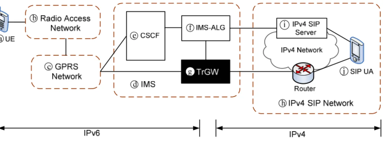
and the IPv4 Session Initiation Protocol (SIP)-based VoIP networks. An interworking example of the IPv6-based IMS and the IPv4 VoIP network is given in Figure 1.
Fig. 1. Interworking between the IPv6-based IMS and the IPv4 VoIP networks
In Figure 1, a User Equipment (UE; see Figure 1 (a)) connects to the Radio Access
(Figure 1 (c)). IMS (Figure 1 (d)) is located between the GPRS network and the packet data network (specifically, the IP network). In IMS, the Call Session Control Function (CSCF; see Figure 1 (e)) can be viewed as a SIP server, which is responsible for call control.
The IPv4 SIP network (Figure 1 (h)) contains SIP servers (Figure 1 (i)) and SIP User
Agents (UAs; see Figure 1 (j)). The SIP registrar function of a SIP server stores the contact
information of each SIP UA [2]. The proxy function of the SIP server forwards SIP messages to a SIP UA according to the routing policy and the information stored in its registrar database. Via SIP, two UAs exchange the codec and the session information to set up a Real-time
Transport Protocol (RTP) session [3].
In the IPv6-based IMS, the UE utilizes IPv6 exclusively to access the IMS services. If the IPv6-based IMS connects to the IPv4 networks, it requires IPv4-IPv6 translation for SIP applications. The IMS-ALG (Figure 1 (f)) and the TrGW (Figure 1 (g)) perform IPv4-IPv6 translation for SIP and RTP packets, respectively. For example, when the UE sends an IPv6 SIP message (e.g., an INVITE message) to the SIP UA, the message passes through the RAN, the GPRS network, the CSCF, the IMS-ALG, the IPv4 SIP Server, and the SIP UA, where the IMS-ALG is responsible for translating the IPv6 SIP message into IPv4. The SIP message translation details are given in [4]. After the RTP session has been established between the UE and the SIP UA, the IPv6 RTP packets sent from the UE to the SIP UA pass through the RAN, the GPRS network, the TrGW and the SIP UA. The TrGW is responsible for translating the
IPv6 RTP packets into IPv4.
In this thesis, we study the IPv4-IPv6 translation performance of the TrGW. The thesis is organized as follows. In Chapter 2, we introduce two existing translation solutions for the TrGW. In Chapter 3, we propose the National Information and Communications Initiative (NICI) solution. In Chapter 4, we measure and evaluate the performance of the three solutions implemented in the TrGW. Finally, we provide conclusions in Chapter 5.
Chapter 2
Related Works
This chapter introduces two IPv4-IPv6 translation solutions for the TrGW: the Naptd solution based on Network Address Translation and Protocol Translation (NAT-PT) [5] [6], and the Portaone solution which is implemented specifically for translating and relaying RTP packets [7] [8]. In the following example, we assume that a UE in IMS (Figure 1 (a)) makes a connection to an IPv4 SIP UA (Figure 1 (j)). We further assume that the IMS-ALG (Figure 1 (f)) stores the IPv4 address and the domain name (sip.ipv4.nctu.edu.tw) of the IPv4 SIP server (Figure 1 (i)), and the SIP UA has registered to the IPv4 SIP server. Therefore the SIP UA has the SIP Uniform Resource Identifier (URI) sip:[email protected].
2.1
The Naptd Solution
We first describe the SIP message flow for establishing IP/port mapping information through Naptd-TrGW. Then we describe how an RTP packet is actually translated at Naptd-TrGW. In our example, Naptd-TrGW maintains a pool of public IPv4 addresses ranging from 140.113.131.13 to 140.113.131.22. These addresses are assigned to the IPv6 UEs when they communicate with the SIP UAs in the IPv4 network. On the other hand, for any IPv4 SIP UA that communicates with an IPv6 UE behind the TrGW, its IPv6 address is generated by concatenating the NAT-PT prefix (2000:ffff::/96 in our example) with the IPv4 address of that
SIP UA.
2.1.1
Message Flow
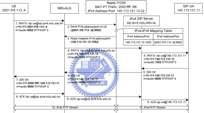
Based on the network architecture described in Figure 1, Figure 2 illustrates the 3GPP 23.228 message flow with Naptd-TrGW. The message flow is described in the following steps:
Fig. 2. SIP message flow with Naptd-TrGW
Step 1. The UE sends an IPv6 INVITE message to the IMS-ALG. In this message, the
Request-URI is sip:[email protected]. The RTP information of the UE is provided
in the c and the m fields of the Session Description Protocol (SDP) [9]. Specifically, the IPv6 address (2001:f18:113::4) of the UE is provided in the c field (c=IN IP6 2001:f18:113::4) and the port number (9002) of the UE is specified in the m field (m=audio 9002 RTP/AVP 0).
Step 2. When the IMS-ALG receives the IPv6 INVITE message, it retrieves the UE’s IPv6 address from the Contact header field and learns that the UE resides in the IPv6 network. The IMS-ALG retrieves the domain name (sip.ipv4.nctu.edu.tw) from the Request-URI and obtains the IPv4 address of the SIP server. By IP version comparison, the IMS-ALG determines that the INVITE message should be translated from IPv6 to IPv4. The IMS-ALG then retrieves the IPv6 address and port number of the UE from the c/m fields and sends this information to the TrGW.
Step 3. The TrGW assigns a free IPv4 address (140.113.131.13) and a port number, e.g., 1052, to the UE and creates an entry (140.113.131.13:1052, [2001:f18:113::4]:9002) in its IPv4-IPv6 mapping table. Then the TrGW returns the mapped IPv4 address and port number to the IMS-ALG.
Step 4. The IMS-ALG generates a new IPv4 INVITE message and fills the IPv4 address (140.113.131.13) and port number (1052) into the c/m fields of the IPv4 INVITE
message. The Request-URI in the new IPv4 INVITE message is copied from the IPv6
INVITE message. The IMS-ALG then sends this new IPv4 INVITE message to the IPv4 SIP server according to the IPv4 address of the IPv4 SIP server obtained at Step 2. Step 5. Upon receipt of the IPv4 INVITE message, the IPv4 SIP server retrieves the IPv4
address of the SIP UA (140.113.13.11) from its registrar database and modifies the
INVITE message to the SIP UA.
Step 6. When the called user picks up the handset, the SIP UA sends an IPv4 200 OK
message to the IMS-ALG. This message specifies the IPv4 address (140.113.131.11) and port number (9000) of the SIP UA in the c/m fields.
Step 7. When the IMS-ALG receives the IPv4 200 OK message, it concatenates the NAT-PT prefix 2000:ffff::/96 with the IPv4 address 140.113.131.11 in the c field to generate the IPv6 address 2000:ffff::140.113.131.11. Then the IMS-ALG generates a new IPv6 200 OK message and fills the IPv6 address into the c field of the IPv6 200 OK message. Then this message is sent to the UE.
Steps 8 and 9. Upon receipt of the IPv6 200 OK message, the UE sends the IPv6 ACK
message to the SIP UA to indicate that the UE has received the IPv6 200 OK message. The Request-URI modification of the ACK message is similar to that of the INVITE
message and the details are omitted.
Step 10. The RTP session is established between the UE and the SIP UA through the TrGW.
The above procedure maps the IPv4 address/port 140.113.131.13:1052 to the IPv6 UE, which is stored in the IPv4-IPv6 mapping table at Step 3. The mapped IPv6 address/port [2000:ffff::140.113.131.11]:9000 of the IPv4 SIP UA is automatically generated without the mapping table. Same mappings are used in the RTP packet translation described in the next subsection.
2.1.2
The RTP Packet Translation at Naptd-TrGW
This subsection describes how an RTP packet is translated at Naptd-TrGW based on NAT-PT mechanism. At Steps 2 and 3 in Figure 2, Naptd-TrGW establishes the IP/port mapping for the UE in the IPv4-IPv6 mapping table. At Step 10 in Figure 2, Naptd-TrGW translates the RTP packets transmitted between the UE and the SIP UA by using the IPv4-IPv6 mapping table. We assume that the RTP packets are sent from the UE to the SIP UA. The source of the packets is [2001:f18:113::4]:9002 and the destination is [2000:ffff::140.113.131.11]:9000.
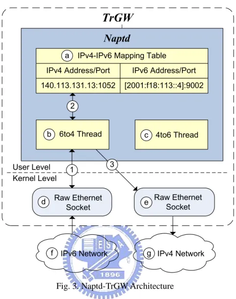
As shown in Figure 3, Naptd is developed as a Linux user-level daemon with an IPv4-IPv6 mapping table (Figure 3 (a)) and two threads. A 6to4 thread (Figure 3 (b)) and a 4to6 thread (Figure 3 (c)) translate RTP packets of all active RTP sessions. At initialization of Naptd, these two threads create an IPv6-network-connected raw Ethernet socket (Figure 3 (d)) and an IPv4-network-connected raw Ethernet socket (Figure 3 (e)) at the Linux kernel for receiving and transmitting the RTP packets. When the UE at the IPv6 network (Figure 3 (f)) sends an IPv6 RTP packet to the TrGW, the packet is stored in the buffer of the IPv6-network-connected raw Ethernet socket (the packet is not processed by the IPv6 protocol stack). The detailed operations of IPv6-to-IPv4 translation are described as follows:
Kernel Level User Level
IPv4-IPv6 Mapping Table
IPv6 Address/Port [2001:f18:113::4]:9002 140.113.131.13:1052 IPv4 Address/Port
Naptd
aTrGW
2 IPv6 Network 1 f e IPv4 Network g c 4to6 Thread Raw Ethernet Socket 6to4 Thread b Raw Ethernet Socket d 3Fig. 3. Naptd-TrGW Architecture
Step 1. The 6to4 thread periodically checks the buffer of the IPv6-network-connected raw Ethernet socket. By polling the socket buffer, the 6to4 thread receives a raw packet (with the Ethernet header, the IPv6 header and the UDP header) at a time. The 6to4 thread parses the raw packet to retrieve the source/destination IPv6 addresses from the IPv6 header, and retrieves the source/destination ports from the UDP header.
Step 2. The 6to4 thread looks up the IPv4-IPv6 mapping table to obtain the mapped IPv4 address/port (140.113.131.13:1052). The destination IPv6 address 2000:ffff::140.113.131.11 is simply translated into the IPv4 address 140.113.131.11 by
removing the NAT-PT prefix 2000:ffff::/96. The destination port 9000 remains the same. The new Ethernet header, other fields of the IPv4 header and the UDP header are filled to the IPv4 packet.
Step 3. The translated IPv4 packet is delivered to the IPv4 network (Figure 3 (g)) through the IPv4-network-connected raw Ethernet socket.
The IPv4-to-IPv6 translation is similar to the above procedure, and the details are omitted. Note that packets for all active RTP sessions from one direction (e.g., the IPv6 network) are all buffered in one raw Ethernet socket.
2.2
The Portaone Solution
This section describes the Portaone IPv4-IPv6 translation solution. We first describe the SIP message flow with Portaone-TrGW for establishing IP/port mapping information. Then we describe how an RTP packet is translated at Portaone-TrGW.
2.2.1
Message Flow
Portaone-TrGW is assigned an IPv4 address and an IPv6 address. The source address of an IPv6 RTP packet from the UE is replaced by the IPv4 address of the TrGW, and the source address of an IPv4 RTP packet from the SIP UA is replaced by the IPv6 address of the TrGW. Portaone uses the same IPv4/IPv6 addresses but different port numbers for different RTP
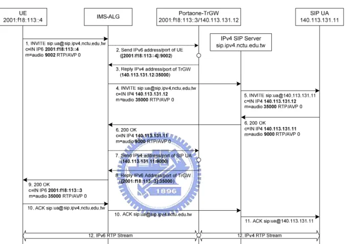
sessions. In our example, the IPv4 address and the IPv6 address are 140.113.131.12 and 2001:f18:113::3, respectively. The message flow is described in the following steps (see Figure 4):
Fig. 4. SIP message flow with Portaone-TrGW
Step 1. The UE sends an IPv6 INVITE message to the IMS-ALG.
Step 2. When the IMS-ALG receives the IPv6 INVITE message, it performs IP version comparison, and determines that the INVITE message should be translated from IPv6 to IPv4. The IMS-ALG then retrieves the IPv6 address and port number of the UE from the
c/m fields and sends this information to the TrGW.
socket (to be described in Section 2.2.2) which is bound to the TrGW’s IPv4 address (140.113.131.12) and an unused port number (35000). Then the TrGW replies its IPv4 address (140.113.131.12) and the port number (35000) to the IMS-ALG.
Step 4. The IMS-ALG generates a new IPv4 INVITE message and fills the IPv4 address (140.113.131.12) and port number (35000) into the c/m fields of the IPv4 INVITE
message. Based on the Request-URI, the IMS-ALG sends this IPv4 INVITE message to the IPv4 SIP server.
Step 5. Similar to Step 5 in Figure 2, the IPv4 SIP server forwards the IPv4 INVITE
message to the SIP UA.
Step 6. When the called user accepts the call, the SIP UA sends an IPv4 200 OK message to the IMS-ALG. This message specifies the IPv4 address (140.113.131.11) and port number (9000) of the SIP UA in the c/m fields.
Step 7. When the IMS-ALG receives the IPv4 200 OK message, it retrieves the IPv4 address and port number of the SIP UA from the c/m fields and sends this information to the TrGW.
Step 8. The TrGW establishes a mapping between the UE’s IPv6 address/port and the SIP UA’s IPv4 address/port. Then it creates an IPv6 UDP socket (to be described in Section 2.2.2) which is bound to the TrGW’s IPv6 address (2001:f18:113::3) and an unused port number (35000). Then Portaone-TrGW replies its IPv6 address (2001:f18:113::3) and
the port number (35000) to the IMS-ALG.
Step 9. The IMS-ALG generates a new IPv6 200 OK message and fills the IPv6 address (2001:f18:113::3) and port number (35000) into the c/m fields of the IPv6 200 OK
message. Then this message is sent to the UE.
Steps 10 and 11. Upon receipt of the IPv6 200 OK message, the UE sends an IPv6 ACK
message to the SIP UA to complete the session setup process.
Step 12. The RTP session is established between the UE and the SIP UA through Portaone-TrGW. The UDP sockets created at Step 3 and Step 8 are responsible for receiving packets from the IPv4 and the IPv6 networks.
Note that the mapping entry for Portaone in Figure 4 is different from that for Naptd. Naptd-TrGW only maintains the IPv4-IPv6 mappings for the UE. Portaone-TrGW maintains the mappings for both the UE and the SIP UA.
2.2.2
The RTP Packet Translation at
Portaone-TrGW
This subsection describes how an RTP packet is translated at Portaone-TrGW. Through SIP signaling at Steps 2 and 3 in Figure 4, Portaone-TrGW obtains the IPv6 address and port number of the UE. At Steps 7 and 8 in Figure 4, Portaone-TrGW obtains the IPv4 address and port number of and SIP UA. Portaone-TrGW then establishes an IPv4/IPv6 mapping entry. At
Step 12 in Figure 4, Portaone-TrGW uses the mapping entry to translate the RTP packets transmitted between the UE and the SIP UA. In our example, the source IPv6 address/port of the RTP packets sent from the UE are [2001:f18:113::4]:9002, and the destination IPv6 address/port of these packets are TrGW’s IPv6 address/port [2001:f18:113::3]:35000.
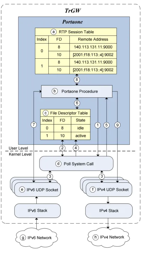
Like Naptd, Portaone is a user-level daemon on Linux as shown in Figure 5. For every RTP session, Portaone creates an IPv6 UDP socket (Figure 5 (e)) and an IPv4 UDP socket (Figure 5 (f)) at the Linux kernel (Step 3 and Step 8 of Figure 4). When a socket is created, a
file descriptor (FD) number is assigned to this socket for RTP packet delivery. The file
descriptor table (Figure 5 (c)) records the FD number and the state of the socket for one direction of each active RTP session. The state of a socket can be idle (no packet in the socket buffer) or active (one or more packets are in the buffer). For each RTP session, the RTP session table (Figure 5 (a)) records the FD numbers of two sockets created for this RTP session (in the FD field), and records the IP/port information of the UE and the SIP UA (in the remote address field). The Portaone procedure (Figure 5 (b)) configures the file descriptor table and the RTP session table, and uses the tables to perform IPv4-IPv6 translation for RTP packets. When the UE at the IPv6 network (Figure 5 (g)) sends an IPv6 RTP packet to the TrGW, the IPv6 protocol stack checks the format of this packet and then passes the packet to the corresponding IPv6 UDP socket. This IPv6 packet is copied to the user-level daemon for translation into IPv4. The IPv6-to-IPv4 translation is described as follows:
Fig. 5. Portaone-TrGW Architecture
Step 1. The Portaone procedure periodically invokes the poll system call (Figure 5 (d)) to see if any packets for the RTP sessions have arrived.
for the RTP sessions. Then it checks if there are packets in the socket buffer of each UDP socket. In our example, no packet is found in the socket buffer of the IPv4 UDP socket (with FD number 8). There are packets in the socket buffer of the IPv6 UDP socket (with FD number 10).
Step 4. The poll system call updates the file descriptor table. Specifically, the state of the IPv6 UDP socket (with FD number 10) is set to “active”, and the state of the IPv4 UDP socket (with FD number 8) is set to “idle”.
Step 5. After the poll system call has updated the states of the sockets in the file descriptor table, it returns to the Portaone procedure.
Step 6. The Portaone procedure sequentially checks the states of the sockets in the file descriptor table, and finds that the socket with index 1 (FD number 10) is active.
Step 7. The Portaone procedure retrieves a packet from the socket buffer with FD number 10.
Step 8. Index 1 is used to retrieve the IPv4-IPv6 mapping entry in the RTP session table. The mapping entry indicates that this packet should be transmitted through the IPv4 UDP socket with FD number 8, and the destination IPv4 address/port is 140.113.131.11:9000 (for the SIP UA).
Step 9. The Portaone procedure forwards the packet to the IPv4 UDP socket (with FD number 8). The packet is copied from the user-level daemon to the Linux kernel. Unlike
Naptd, the Ethernet header, the IPv4 header and the UDP header are all filled by the Linux kernel. The source of the IPv4 RTP packet is translated into the IPv4 address/port of the IPv4 UDP socket (i.e., 140.113.131.12:35000). The destination of this packet is translated into the SIP UA’s IPv4 address/port 140.113.131.11:9000. Then the IPv4 RTP packet is transmitted to the IPv4 network (Figure 5 (h)).
The Portaone procedure repeats Step 7 to Step 9 to receive packets from the IPv6 UDP socket until all buffered packets are processed. Then it returns to Step 6 to check the next active socket recorded in the file descriptor table. After the Portaone procedure has scanned all sockets, it returns to Step 1 to invoke the poll system call to update the file descriptor table. Unlike Naptd, the packets of different RTP sessions are buffered in different UDP sockets in Portaone.
Chapter 3
The NICI Solution
This chapter describes the NICI IPv4-IPv6 translation solution. The NICI solution can be implemented based on either Naptd or Portaone. Since RFC 4215 recommends that NAT-PT should not be used or be used under strict conditions for security reasons [10], we developed NICI-TrGW based on the Portaone solution. The SIP message flow for establishing IP/port mapping information at NICI-TrGW is the same as that for Portaone-TrGW (see Figure 4).
In the NICI solution, the IPv4-IPv6 translation module is embedded in the Linux kernel to avoid packet-copy operations between the Linux kernel and the user-level daemon. The NICI-TrGW architecture and the detailed IPv4-IPv6 translation operations at NICI-TrGW are described as follows.
3.1
The RTP Packet Translation at NICI-TrGW
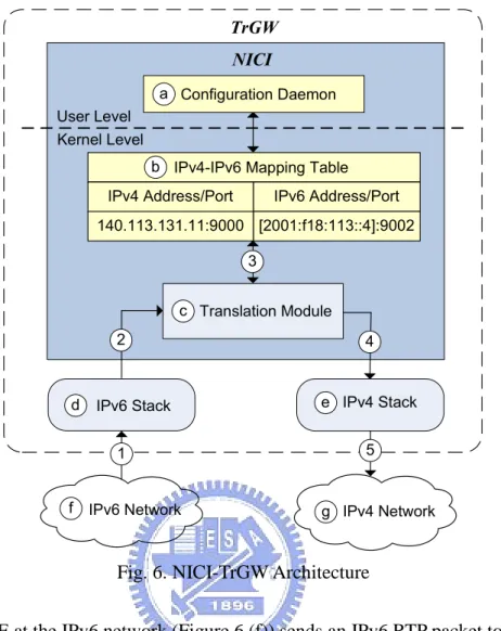
NICI-TrGW consists of a user-level configuration daemon, an IPv4-IPv6 mapping table and a kernel-level translation module as shown in Figure 6. The user-level configuration daemon (Figure 6 (a)) configures the address mappings in the IPv4-IPv6 mapping table (Figure 6 (b)). The NICI IPv4-IPv6 mapping table in the Linux kernel is the same as that of Portaone except that NICI-TrGW looks up the table by hashing while Portaone-TrGW looks up the table by indexing.
Like Portaone-TrGW, at Steps 2 and 3 in Figure 4, the configuration daemon obtains the IPv6 address/port of the UE (e.g., [2001:f18:113::4]:9002 in our example) for sending RTP packets from the TrGW to the UE. At Steps 7 and 8 in Figure 4, the configuration daemon obtains the IPv4 address/port of the SIP UA (140.113.131.11:9000) for sending RTP packets from the TrGW to the SIP UA. The configuration daemon then establishes a mapping entry between the UE’s IPv6 address/port and the SIP UA’s IPv4 address/port, and inserts this entry into the IPv4/IPv6 mapping table. At Step 12 of Figure 4, the translation module (Figure 6 (c)) translates the RTP packets transmitted between the UE and the SIP UA by utilizing the IPv4-IPv6 mapping table. Like the previous example, the source IPv6 address/port of the RTP packets sent from the UE are [2001:f18:113::4]:9002, and the destination IPv6 address/port of these packets are TrGW’s IPv6 address/port [2001:f18:113::3]:35000.
In NICI-TrGW, the IPv4/IPv6 protocols stacks are slightly modified so that the IPv6 RTP packet is directly sent to the translation module without being buffered at the UDP sockets. The detailed IPv6-to-IPv4 translation procedure is described as follows:
NICI Translation Module 3 c Kernel Level User Level IPv6 Address/Port [2001:f18:113::4]:9002 140.113.131.11:9000 IPv4 Address/Port
b IPv4-IPv6 Mapping Table
TrGW IPv6 Stack IPv6 Network 2 Configuration Daemon a 4 IPv4 Network f g IPv4 Stack e d 1 5
Fig. 6. NICI-TrGW Architecture
Step 1. The UE at the IPv6 network (Figure 6 (f)) sends an IPv6 RTP packet to NICI-TrGW. Step 2. The IPv6 protocol stack (Figure 6 (d)) checks the format of the IPv6 RTP packet and
passes this packet to the translation module.
Step 3. The translation module looks up the IPv4-IPv6 mapping table to retrieve the mapped destination IPv4 address/port 140.113.131.11:9000 (for the SIP UA). Then the NICI translation module translates the IPv6 RTP packet into IPv4. Like Naptd, the translation module is responsible for filling the UDP header, the IPv4 header and the Ethernet header. The source of the packet is translated into the TrGW’s IPv4 address/port (140.113.131.12:35000). The destination of the packet is translated into the IPv4
address/port of the SIP UA (140.113.131.11:9000). The Ethernet header, other fields of the IPv4 header and the UDP header are also filled by the translation module.
Steps 4 and 5. The translated RTP packet is passed to the IPv4 protocol stack (Figure 6 (e)) and then to the IPv4 network (Figure 6 (g)).
Chapter 4
Performance Evaluation
This chapter evaluates the performance of the three IPv4-IPv6 translation solutions (Naptd, Portaone, and NICI) implemented in the TrGW.
4.1
The Test Environment
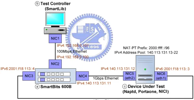
According to the test architecture defined in RFC 2544 [11], Figure 7 illustrates our test environment for IPv4-IPv6 translation, which consists of three components: a SmartBits 600B (Figure 7 (a)) [12], a test controller (Figure 7 (b)) and the Device Under Test (DUT, Figure 7 (c)). The SmartBits 600B is the traffic generator that simultaneously transmits and receives the RTP packets. The test controller is a desktop computer, which invokes the SmartLib functions to control the SmartBits, and is responsible for producing the measured results. The DUT is the TrGW with the IPv4-IPv6 translation software (Naptd, Portaone or NICI). The TrGW is a desktop computer running Linux 2.6 with Intel Pentium 4 3.00GHz CPU and 1.5GB SDRAM. These network components are connected through the following Network
Interface Cards (NICs): NIC1 (in the test controller), NIC2, NIC3, NIC4 (in the SmartBits),
NIC5 and NIC6 (in the DUT).
For Naptd-TrGW, the NAT-PT parameters such as the IPv4 interface name (e.g., eth2 associated with the IPv4 address 140.113.131.12), the IPv6 interface name (e.g., eth1
associated with the IPv6 address 2001:f18:113::3), the NAT-PT prefix (e.g., 2000:ffff::/96) and the IPv4 address pool range (e.g., 140.113.131.13-22) are specified beforehand and recorded in a configuration file. When Naptd-TrGW is initiated, the configuration file is read to set these parameters. For Portatone-TrGW, configuration parameters such as the IPv4 address (e.g., 140.113.131.12) and the IPv6 address (e.g., 2001:f18:113::3) to be listened on by the TrGW are specified as command line arguments when Portaone is initiated. For NICI-TrGW, these two parameters are specified beforehand in the kernel source code.
Fig. 7. The Test Environment for IPv4-IPv6 Translation
In the test environment (Figure 7), the IP address configuration follows the descriptions in Chapters 2 and 3. The test controller and the SmartBits are connected through a private network with the IP addresses 192.168.0.101 and 192.168.0.100, respectively. Before a test run is started, the IP/port mapping information for every call was established following the
message flow in Figure 2 (for Naptd-TrGW) and Figure 4 (for Portaone-TrGW and NICI-TrGW). After IP/port mapping, the IPv6 RTP packets generated at the SmartBits are sent from NIC3 (with IPv6 address 2001:f18:113::4) to NIC6 (with IPv6 address 2001:f18:113::3) over a 1Gbps Ethernet link. After the IPv6 packets have been translated into IPv4 by the TrGW, these IPv4 packets are sent from NIC5 (with IPv4 address 140.113.131.12) to NIC4 (with IPv4 address 140.113.131.11) over another 1Gbps Ethernet link. Packets for IPv4-to-IPv6 translation are delivered in the reverse order.
In our study, the SmartBits generates multiple RTP streams. For each RTP stream, the SmartBits generates 10,000 RTP packets. The packet transmission interval is 20 ms, which is the default packetization interval suggested by RFC 3551 for audio codecs [13]. To conduct a stringent case investigation, the G.711 codec is selected because the size of an encoded G.711 packet is the largest among all codecs, which will consume most network and CPU resources as compared with other codecs. For G.711, a 214-byte IPv4 RTP packet consists of a 14-byte Ethernet header, a 20-byte IPv4 header, an 8-byte UDP header, a 12-byte RTP header and a 160-byte payload. For an IPv6 RTP packet, the IPv4 header is replaced by an IPv6 header (40 bytes) and its packet size is 234 bytes.
4.2
The Measured Results
The output measures in our study are the packet loss rate, the average latency and the maximum throughput. Both the packet loss rate and the average latency are important factors that affect voice quality [14]. The maximum throughput is defined as the maximum number of concurrent calls that can be supported by the TrGW such that none of the RTP packets are dropped [15]. That is, the maximum throughput indicates the capacity (in terms of the number of concurrent calls) of the TrGW. In our study, the single socket buffer of Naptd-TrGW can store 256N RTP packets, where N is the number of concurrent calls. In Portaone-TrGW, every call is assigned a socket buffer that can store 256 RTP packets. NICI-TrGW does not require the socket buffers for delivering packets to the user-level daemon.
4.2.1
Packet Loss Rate and Maximum Throughput
Figure 8 (a) illustrates the packet loss rate for IPv6-to-IPv4 translation measured by the SmartBits. This figure shows that the maximum throughputs without incurring packet loss for Naptd-TrGW and Portaone-TrGW are 478 and 1592 concurrent calls, respectively. We notice that beyond the maximum throughput, the packet loss rate increases significantly. For example, when the number of concurrent calls increases from 500 to 600, the packets loss rate increases from 4.54% to 26.28% for Naptd-TrGW. When the number of concurrent calls increases from 1700 to 1800, the packet loss rate increases from 6.51% to 32.67% for
Portaone-TrGW. This figure also indicates that NICI-TrGW can support more than 2000 G.711 concurrent calls without packet loss. That is, the maximum throughput for NICI-TrGW is not reached when the number of concurrent calls is less than 2000. Clearly, NICI-TrGW outperforms Portaone-TrGW and Naptd-TrGW in terms of the packet loss rate and the maximum throughput.
(a) IPv6-to-IPv4 Translation (b) Naptd IPv4-to-IPv6 and IPv6-to-IPv4 Fig. 8. The Packet Loss Rate
The packet loss rate and the maximum throughput of IPv4-to-IPv6 translation are the same as those of IPv6-to-IPv4 translation for both Portaone-TrGW and NICI-TrGW. Figure 8 (b) illustrates the Naptd-TrGW packet loss rates for IPv4-to-IPv6 and IPv6-to-IPv4 translations. This figure shows that the maximum throughputs for IPv4-to-IPv6 and
IPv6-to-IPv4 translations are 603 and 478 concurrent calls, respectively. That is, IPv4-to-IPv6 translation performs better than IPv6-to-IPv4 translation in terms of the packet loss rate and the maximum throughput. We will explain this phenomenon in Subsection 4.2.2.
4.2.2
Average Latency
Figure 9 (a) illustrates the average latency for IPv6-to-IPv4 translation. This figure shows that the average latency for NICI-TrGW is the shortest among the three translation solutions. The average latency for Naptd-TrGW is, e.g., about 78% higher than that for NICI-TrGW when the number of concurrent calls is 400. The average latency for Portaone-TrGW is much higher than that for Naptd-TrGW. Compared with NICI-TrGW, the high latencies of Naptd-TrGW and Portaone-TrGW are due to the fact that both translation solutions translate packets at the user level. That is, every incoming packet is copied from the Linux kernel to the user-level daemon. After the packet is translated, it is copied again from the user-level daemon to the Linux kernel. For NICI-TrGW, the translation module is implemented at the kernel level. Therefore, it avoids these memory copies and thus can process packets faster than Naptd-TrGW and Portaone-TrGW.
(a) IPv6-to-IPv4 Translation (b) Naptd IPv4-to-IPv6 and IPv6-to-IPv4 Fig. 9. The Average Latency
For both NICI-TrGW and Naptd-TrGW, the average latencies slightly increase as the number of concurrent calls increases. For example, when the number of concurrent calls increases from 100 to 200, the average latency increases from 102.4 µs to 107.2 µs for Naptd-TrGW. For Portaone-TrGW, the average latency increases significantly when the number of concurrent calls increases. For example, when the number of concurrent calls increases from 100 to 200, the average latency increases from 143 µs to 322.1 µs. This large latency increase for Portaone-TrGW is explained as follows. When the number of concurrent calls increases, the number of file descriptors recorded in the file descriptor table increases, which results in high overhead for invoking the poll system call and more packets are held in
the socket buffers before the poll system call returns (see Section 2.2.2). Therefore, the average packet waiting time increases and thus the average latency increases.
For Naptd-TrGW, Figure 9 (b) illustrates that the average latency of IPv6-to-IPv4 translation is much higher than that of IPv4-to-IPv6 translation because Naptd-TrGW performs linear search when it looks up the mapping table, where the 32-bit IPv4 address search (for IPv4-to-IPv6 translation) is faster than the 128-bit IPv6 address search (for IPv6-to-IPv4 translation). On the other hand, both Portaone-TrGW and NICI-TrGW look up the mapping tables with near constant delays, and thus there is no significant difference between IPv4-to-IPv6 and IPv6-to-IPv4 translations.
Chapter 5
Conclusions
This thesis investigated the IPv4-IPv6 translation issue for interworking between the IPv6-based IMS and the IPv4 VoIP network. We developed a transition gateway called NICI-TrGW to improve the IPv4-IPv6 translation performance based on the Portaone solution. By translating the RTP packets at the Linux kernel, NICI-TrGW avoids the packet-copy operations between the Linux kernel and the user-level daemon. Our measurement results show that NICI-TrGW outperforms Naptd-TrGW and Portaone-TrGW in terms of three different output measures including packet loss rate, maximum throughput, and average latency. In the future, we will design a multiple-TrGW architecture for load balancing and fault tolerance.
Bibliography
[1] 3GPP. 3rd Generation Partnership Project; Technical Specification Group Services and Systems Aspects; IP Multimedia Subsystem; Stage 2. Technical Specification 3G TS 23.228 version 8.3.0 (2007-12), 2007.
[2] IETF. SIP: Session Initiation Protocol. IETF RFC 3261, June 2002.
[3] IETF. RTP: A Transport Protocol for Real-Time Applications. IETF RFC 3550, July 2003.
[4] Chen, W.-E., Lin, Y.-B., and Pang, A.-C. An IPv4-IPv6 Translation Mechanism for SIP Overlay Network in UMTS All-IP Environment. IEEE Journal on Selected Areas in
Communications, 23(11):2152–2160, November 2005.
[5] IETF. Network Address Translation - Protocol Translation (NAT-PT). IETF RFC 2766, February 2000.
[6] Naptd. http://tomicki.net/naptd.php/.
[7] Sisalem, D., Fiedler, J., and Ruppelt, R. SIP and IPv6: Why and How. SAINT2003,
Orlando (Florida, USA), pages 27–31, January 2003. [8] Portaone RTPproxy. http://www.rtpproxy.org/.
[9] IETF. SDP: Session Description Protocol. IETF RFC 4566, July 2006.
[10] IETF. Analysis on IPv6 Transition in Third Generation Partnership Project (3GPP) Networks. IETF RFC 4215, October 2005.
[11] IETF. Benchmarking Methodology for Network Interconnect Devices. IETF RFC 2544, March 1999.
[12] Spirent Smartbits performance analysis system. http://www.spirent.com/.
[13] IETF. RTP Profile for Audio and Video Conferences with Minimal Control. IETF RFC 3551, July 2003.
[14] Collins, D. Carrier Grade Voice Over IP. 2nd Edition. McGraw-Hill, Singapore, 2003. [15] IETF. Benchmarking Terminology for Network Interconnection Devices. IETF RFC