國
立
交
通
大
學
材料科學與工程學系
博 士
論
文
設計與製備多功能孔洞二氧化矽基板奈米平台
應用於提高療效與增強影像之研究
Design and Characterization of Multifunctional Mesoporous
Silica Nanoplatform for Enhanced Therapy
and Imaging Modality
研究生:陳柏溶
指導教授:陳三元/劉典謨 教授
設計與製備多功能孔洞二氧化矽基板奈米平台
應用於提高療效與增強影像之研究
Design and Characterization of Multifunctional Mesoporous Silica Nanoplatform for Enhanced Therapy and Imaging Modality
研 究 生:陳柏溶 Student:Po-Jung Chen
指導教授:陳三元/劉典謨 Advisor:San-Yuan Chen/Dean-Mo Liu
國 立 交 通 大 學
材 料 科 學 與 工 程 學 系
博 士 論 文
A Thesis
Submitted to Department of Materials Science and Engineering College of Engineering
National Chiao Tung University In partial Fulfillment of the Requirements
For the Degree of Doctor of Philosophy
in
Materials Science and Engineering July 2013
Hsinchu, Taiwan, Republic of China
i
設計與製備多功能孔洞二氧化矽基板奈米平台
應用於提高療效與增強影像之研究
研究生:陳柏溶 指導教授:陳三元/劉典謨 國立交通大學材料科學與工程學系摘要
奈米載體結合診斷與治療等多功能的系統,在全球已經引起各學界與業界人士的注意。 在本論文中,利用材料、奈米粒子與藥物的結合,設計與製備具多功能的磁性奈米載體 與具高強度光反應的顯影載體。除了具有利用外部磁場或雷射光控制釋放治療之功能外, 並可以同步監測奈米載體的位置。然而,目前的多功能奈米載體仍然具有許多缺點需要 改善,例如:無法長時間監控載體,容易受外界環境影響載體的穩定性。為了改善這些 缺點,本論文發展出一個結合診斷與治療於一身的多功能二氧化矽載體。於本論文第一 部分研究,首先,以孔洞二氧化矽當作基材,將抗癌藥物載入孔洞中,並利用單分散氧 化鐵奈米粒子藉由化學鍵和孔洞二氧化矽奈米粒子鍵結。此化學鍵提供氧化鐵奈米粒子 和孔洞性二氧化矽奈米粒子有緊密的鍵結,並且當作奈米蓋子完整覆蓋於二氧化矽的孔 洞表面。在沒有外加磁場刺激之下,近乎沒有藥物從磁性奈米載體裡面外漏出來。然而, 當我們施加可控制的外加磁場刺激之下,磁性奈米載體表面的氧化鐵粒子將會脫落,使 得二氧化矽孔洞外漏出來,進而讓孔洞裡面的抗癌藥物釋放出來。此磁性奈米載體具有 高強度的核磁共振顯影效果與螢光顯影的特性,比較於其他類似的結構更為出色。 另一方面,由於孔洞二氧化矽材料受限於孔洞的大小,孔洞太小無法攜帶大分子藥物 與功能性奈米粒子,限制其應用性。因此,於論文第二部分,我們將功能性量子點載入 於 10 奈米孔洞大小的二氧化矽球中,並且透過非共價鍵的生物分子架接標靶分子,此載體具有良好的光對比特性與多重色碼標示的優點,更可以大幅降低量子點會受到外界 環境影響的特性,保護量子點維持其量子效應,並且改善量子點的生物相容性差的缺點, 最後在標靶分子方面,具有標靶分子的載體在腫瘤細胞的標靶具有很明顯的差異。透過 此簡易的乘載方法,使量子點在生物醫學應用上有很大的突破。 同時,在第三部分,設計另一種新型多功能奈米複合結構的奈米載體,其結構是由奈 米金棒填滿孔洞二氧化矽球,並且具有高度強度且穩定性的光聲顯影效果。可當作一種 新型的光聲顯影之顯影劑,這種光聲顯影是一種結合超音波及雷射所發展出之一種具有 低成本及良好顯影的技術,可以應用偵測腫瘤及一些的病態組織,而其中當然最重要的 是顯影劑。而奈米金棒成長填滿於孔洞奈米結構,則可以應用在這方面來當顯影劑,此 奈米金棒於高強度的奈米秒發間歇性雷射照射之下,仍然具有且保留良好的光學特性與 光熱穩定度,而且無論於生物體外和生物體內都具備了穩定的光聲顯影和高效率的熱治 療,由此可以得知奈米金棒成長填滿多孔性球具有強而有力的奈米診斷治療能力。此外, 奈米金棒填滿多孔性球也具有良好的生物相容性與低毒性的特性。所以,奈米金棒填滿 孔洞球,的確可以成為一個具有熱治療與光聲顯影的奈米診斷治療平台。最後,將此奈 米金棒填滿孔洞球與磁性氧化鐵結合,形成同時具備有磁特性、光特性奈米載體與核磁 共振顯影和光聲顯影雙重顯影的功能。利用磁導引的特性,在光聲顯影方面,提升了將 近 7.2 倍的影像強度,另一方面,應用於幹細胞治療上,奈米載體經由幹細胞吞噬之後, 透過磁導引的方式,將幹細胞引導至中風部位,大幅降低於人體中幹細胞90%會被肝跟 肺所代謝。未來期望能透過多功能的奈米載體達到新一代的治療與診斷效果。 關鍵字: 控制釋放,孔洞二氧化矽,影像顯影,磁標靶
iii
Design and Characterization of Multifunctional Mesoporous Silica
Nanoplatform for Enhanced Therapy and Imaging Modality
Student: Po-Jung Chen Advisor: San-Yuan Chen/Dean-Mo Liu
Department of Materials Science and Engineering National Chiao Tung University
Abstract
Multifunctional nanoprobes have been received greatest attention worldwide, especially combining diagnostic and therapeutic functions. In order to enhance imaging and therapy efficiency, the use of the mesoporous silica nanoparticles as a new type of actuator platforms to anchor guest molecules has been developed in this thesis. In first part, an anticancer drug, (S)-(+)-Camptothecin (CPT)) were encapsulated into the mesoporous silica nanoparticles which is chemically capping by Fe3O4 to prevent drug elapsing and remote-controllable. With
an external high frequency magnetic field (HFMF) trigger, the Fe3O4 nanocaps can be
removed from surfaces of mesoporous silica vehicles due to the breaking of chemical bonds and then subsequently lead a fast-responsive drug release and concentration gradient for second drug release. The nanosystems also show the potential of magnetic resonance imaging and fluorescence imaging for diagnostic. In second part, the meosporous silica matrix was enlarged the pore size to incorporate quantum dots for bioimaging. A highly hydrophobic mesoporous silica nanoparticle with pore size greater than 10 nm was incorporating quantum dots and bridging the targeting peptide cRGD by using noncovalent biotin-streptavidin link. Their outstanding optical contrasts render these highly fluorescent QDs ideal fluorophores for wavelength-and-intensity multiplex color coding. This nanoprobe is able to provide highly chemically stability for the quantum dots and maintain the high quantum yield even in the low
pH value environment. For the targeting effect, the cRGD-encoded lipid coated QDs tagged nanobeads exhibited significantly increased αvβ3-expressing cell targeting toward MCF-7
breast cancer cells over the αvβ3-low expressing in HeLa cervix cancer cells. Furthermore, in
MCF-7 xenograft nude mice, the cRGD-encoded nanoprobes revealed prolonged accumulation time at tumor site.
In third part, we a new type of theranostic system based on gold nanorod-containing mesoporous silica nanobeads with exceptionally efficient and stable photoacoustic imaging modality was synthesized. The novel nano-seaurchin structure is characteristic of high-density and well-dispersive gold nanorods (AuRNBs) in one mesoporous silica nanobead. The optical properties and photothermal stability of porous silica nanobeads with pore-filled gold nanorods (AuRNBs) under intense irradiation with nanosecond laser pulses were investigated by UV-Vis spectroscopy and transmission electron microsocopy. The AuRNBs showed increased photothermal stability and retained their superior optical properties under much higher fluence laser pulses at 10 mJ/cm2. The AuRNBs also provided a stable photoacoustic signal and highly efficient hyperthermia effect both in vitro and in vivo, indicating a powerful theranostic modality.
Finally, the mesoporous silica nanobeads tagged iron oxides nanoparticles, where the nanoporosity was further filled with gold nanorods. The magnetic nanoprobes could be controlled by external magnetic navigation, capable of performing MR and photoacoustic imaging modalities simultaneously. The magnetic nanoprobes showed that the r1 value was
1.205 s-1mM-1Fe, and the r2 value was 127.89 s-1mM-1Fe. The higher transverse (r2)
relaxivities could be attributed to the silica nanobeads tagged the Fe3O4 NPs in the pore
forming a well-dispersive and chemical stable condition. On the other hand, the PA contrast could be further increased 7.2 times PA signals by an external magnet PA signals compare with without an external magnet applied, demonstrating their ability to perform active magnetic guide. The magnetic nanoprobes could be internalized efficiently toward the stem
v
cells and a prolonged retention for 48 hours. In addition, the magnetic nanoprobes were successfully achieved using an external magnet guiding the stem cells to the stroke areas and cell labeling by MR images for in vivo MCAO stroke mouse. Therefore, this multifunctional nanoprobe not only provides exceptionally highly photothermal stability but also remote-controlled property, which offers potential advantages for carrying/homing stem cell, therapy and dual imaging.
Keywords: remote-controlled, mesoporous silica nanoparticles, imaging modality, magnetic
target
致謝
經過碩士班一年和博士班四年的時間努力之下,終於在 2013 年取得博士學位。想當 初剛進來交通大學念研究所的時候,對於實驗的掌握度和技巧都是那麼的生澀懵懂,在 學習的過程中也是遭遇了許多困境與瓶頸,可喜的是都能克服這些難題,順利取得口試 資格與博士學位。 在碩博五年的時間裡,遇到了許多貴人的幫忙與協助。首先感謝我的指導教授陳三元 老師和劉典謨老師的提拔與教導,還記得碩一的時候,陳三元老師問我要不要直接逕博, 在老師的啟發之下,繼續攻取博士學位。陳三元老師不只在實驗研究方面教導我,更於 生活和未來的規劃上關心與照顧著我,在老師身上也學到如何與人相處技巧和方法。劉 典謨老師在學術實驗上總是有許多創新與與新穎的看法與見解,在老師的身上學習到世 界觀,讓我知道世界是如此之大,並且在老師的教導之下,實驗想法和英文能力都有很 大的提升。還有要感謝胡尚秀學長,在碩一的時候帶著懵懂的我進行實驗設計與實驗概 念,讓我快速的成長,感謝蕭繼聖學長在電子顯微鏡上的幫助與討論。另外,也要感謝 黃信揚、蕭孟軒、周昊勳、李偉銘、蘇嘉偉、王衍人、張博學、陳又維、江智聖、黃薇 蓁、楊翊筠等實驗室學長與同學的照顧,帶給我歡樂的實驗室生活,也特別感謝康宜達 學弟協助我完成許多實驗。 最後也要感謝我的家人長久以來的支持和鼓勵,讓我可以無後顧之憂專注於我的學業 研究,感謝佩鈴的照顧與陪伴,感謝我的電腦陪我渡過漫長的博士生活,沒有耍脾氣的 當機。未來將是另一段人生路程,期望自己可以貢獻一己之力,對整個社會有所幫助。vii
Content
摘要 ... i Abstract ... iii 致謝 ... vi Figure Captions ... xi Chapter 1 Introduction ... 1Chapter 2 Literature Review and Theory ... 5
2.1 Introduction of nanosystems for detection and treatment of diseases ... 5
2.2 Remote-controlled mesoporous silica nanoparticles for drug delivery ... 6
2.2.1 Synthesis of mesoporous silica nanoparticles ... 7
2.2.2 Nanoparticles cap porous silica nanoparticles for drug delivery ... 10
2.2.3 Responsive molecules with mesoporous silica nanoparticles for drug delivery ... 12
2.3 Gold nanostructure for biomedical applications ... 13
2.3.1 Synthesis of gold nanostructure ... 14
2.3.2 Photoacoustic imaging for gold nanostructure ... 16
2.3.3 Gold nanostructures integrate with silica for phtothermal therapy ... 19
2.4 Magnetic nanoparticles for biomedical applications ... 20
2.4.1 Synthesis of magnetic nanoparticles ... 22
2.4.2 Magnetic nanoparticles for high performance magnetic resonance imaging and guiding effect ... 23
2.4.3 Magnetic nanoparticles/silica core-satellite structure for dual-mode imaging ... 26
2.4.4 Magnetic nanoparticles for stem cell therapy ... 27
Chapter 3 Experimental Procedures ... 31
3.1 Experimental overviews ... 31
3.2 Characterization ... 31
3.3High frequency magnetic field (HFMF) ... 32
3.5 Cell culture ... 34
3.6 In vivo experiment... 35
Chapter 4 Multifunctional Magnetically Removable Nanogated Lids of Fe3O4 –Capped Mesoporous Silica Nanoparticles for Intracellular Controlled Release and MR Imaging ... 36
4.1 Introduction ... 36
4.2 Experimental section ... 38
4.3 Preparation of MSN@Fe3O4 nanocarriers ... 40
4.4 Characterization of MSN@Fe3O4 nanocarriers ... 42
4.5 Drug release of CPT-loaded MSN@Fe3O4 and under magnetic stimulus ... 44
4.6 Operation mechanism of the nanocarriers under magnetic stimulus ... 45
4.7 Cell uptake and cell viability under magnetic stimulus ... 51
4.8 Magnetic resonance behavior of MSN@Fe3O4 nanocarriers ... 52
4.9 Summary ... 54
Chapter 5 Geometrical Confinement of Quantum Dots in Porous Nanobeads with Ultra-efficient Fluorescence for Cell-specific Targeting and Bioimaging ... 56
5.1 Introduction ... 56
5.2 Experimental section ... 58
5.3 Preparation and of cRGD-conjugated quantum dots in porous silicananobeads ... 60
5.4 Characterization of QNBs nanoprobes ... 62
5.5 Optical coding of quantum dots in silica nanobeads ... 66
5.6 Cell uptake and flow cytometry for targeting effect ... 67
5.7 In vivo target effect of cRGD-encode LQNBs ... 71
5.8 Summary ... 73
Chapter 6 A Novel Multifunctional Nano-platform with Enhanced Anti-cancer and Photoacoustic Imaging Modalities using Gold-nanorod-filled Silica Nanobeads ... 74
6.1 Introduction ... 74
ix
6.3 Preparation of mesoporous silica nanobeads with gold nanorods filled nano-seaurchin
structure (AuRNBs) ... 78
6.4 Growing gold nanorods with different aspect ratios ... 81
6.5 Thermal stability of AuRNBs ... 82
6.6 Mechanism for the photoacoustic signal enhancement ... 83
6.7 In vitro and in vivo photoacoustic signal of pure AuR and AuRNBs ... 84
6.8 Cell uptake ... 85
6.9In vitro photothermal efficacy and cell viability ... 87
6.10 In vivo photothermal efficacy ... 89
6.11 Summary ... 91
Chapter 7 Magnetic Mesoporous Silica Nanobeads Filled with Gold Nanorods for Dual-modal Imaging-Guided Stem Cell Therapy under Magnetic Remote-Controlled . 92 7.1 Introduction ... 92
7.2 Experimental section ... 94
7.3 Preparation of magnetic gold-containing silica nanobeads (GRMNBs)... 95
7.4 Characteristic and thermal stability of GRMNBs ... 98
7.5 Magnetic properties of GRMNBs ... 99
7.6 In vitro and in vivo photoacoustic signals of GRMNBs ... 100
7.7 Stem cell uptake ... 104
7.8 In vivo stem cell therapy for MCAO stroke ... 105
7.9 Summary ... 107
Chapter 8 Conclusion ... 109
8.1 Removable nanogated lids of Fe3O4 –capped mesoporous silica nanoparticles ... 109
8.2 Geometrical confinement of quantum dots in porous nanobeads ... 109
8.3 Gold-nanorod-filled silica nanobeads ... 110
8.4 Magnetic mesoporous silica nanobeads filled with gold nanorods ... 110
Curriculum Vitae ... 119 Publications ... 120
xi
Figure Captions
Figure 2.1 The nanosystems design strategies for containing both therapeutic and diagnostic
nanocomponents. ... 6
Figure 2.2 Structures of mesoporous M41S materials: (a) MCM-41, (b) MCM-48 and (c)
MCM-50 type. [39] Copyright 2006, Wiley-Vch. ... 8
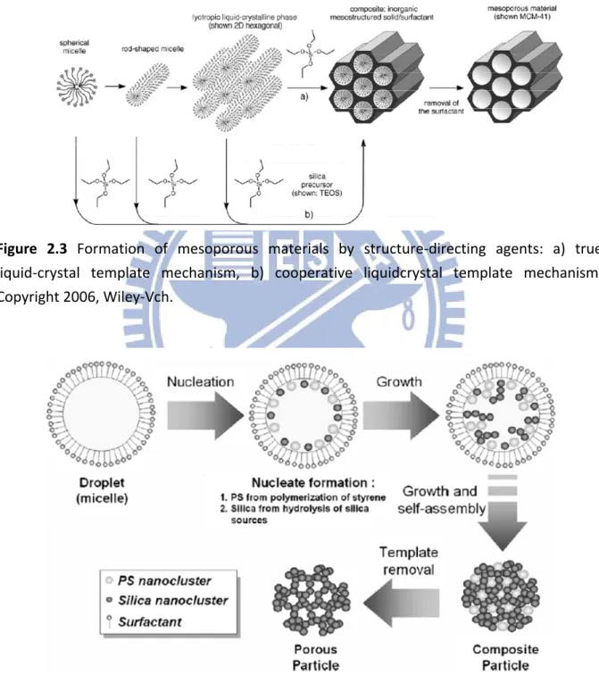
Figure 2.3 Formation of mesoporous materials by structure-directing agents: a) true liquid-
crystal template mechanism, b) cooperative liquidcrystal template mechanism. Copyright 2006, Wiley-Vch. ... 9
Figure 2.4 Formation of mesoporous materials by using hydrolytic condensation of tetra-
orthosilicate (TEOS) and polymerization of styrene into polystyrene (PS). Copyright 2008, Elsevier Inc... 9
Figure 2.5 Schematic representation of the CdS nanoparticle-capped MSN based drug/
neurotransmitter delivery system. The controlled-release mechanism of the system is based on chemical reduction of the disulfide linkage between the CdS caps and the MSN hosts. Copyright 2003, American Chemical Society. ... 11
Figure 2.6 (A) Synthetic route to Si-MP-CD: (1) 3-aminopropyltriethoxysilane; (2) succinic
anhydride and triethylamine; (3) removal of CTAB, calcein, CuSO4, sodium ascorbate, and mono-6-azido-_-CD. (B) FE-SEM image of Si-MP-CD. (C) The structure of surface functional motifs on Si- MP-NBE-CD. (D) Schematic illustration for enzyme-triggered release of guest molecules from the pore of CD-covered nanocontainers. Copyright 2009, American Chemical Society. ... 13
Figure 2.7 (a) Localized surface plasmon resonance (LSPR) is another critical property of
gold nanostructures that results from the collective oscillation of delocalized electrons in response to an external electric field. (b) multiply twinned gold nanoparticles. (c) gold nanoshells (silica beads coated with a polycrystalline gold layer). (d) gold nanorods, and (e) gold nanocages. [53] Copyright 2011, Royal Society of Chemistry. ... 16
Figure 2.8 Photoacoustic microscopy (PAM) system. Copyright 2008, IEEE. ... 18 Figure 2.9 (a) TEM image of PEGylated gold nanorods. TEM images of gold-silica core-shell
nanorods with (b) 6 nm, (c) 20 nm. (d) 75nm thichness of silica coating.(e) ultrasound, photoacoustic and combined ultrasound and photoacoustic images of PEGylated gold nanorods and gold-silica core-shell nanorods with 6 nm, 20 nm and 75 nm silica coating. [58] Copyright 2011, American Chemical Society. ... 19
Figure 2.10 (a) Schematic diagram and TEM image of GSNs synthesis and bioconjugation. (b)
The photo image of a MCF-7 tumor-bearing BALB/c nude mouse under an 808 nm NIR laser light irradiation. [59] Copyright 2012, Wiley-Vch. ... 20
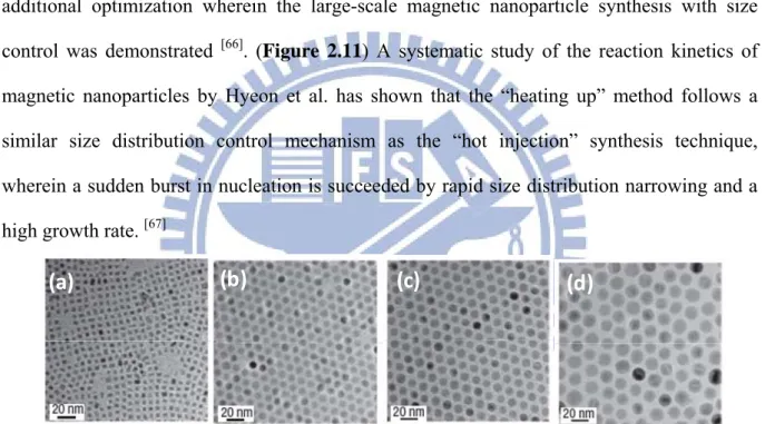
(c) 12 nm and (d) 16 nm. Copyright 2004, Nature Publishing Group. ... 23
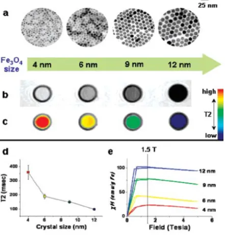
Figure 2.12 Nanoscale size effect of magnetic nanoparticles on magnetism and induced MR
signals. (a) TEM images of Fe3O4 nanoparticles of 4 to 6, 9, and 12 nm. (b) Size-dependent T2-weighted MR images of magnetic nanoparticles in aqueous solution at 1.5 T. (c) Size-dependent changes from red to blue in color-coded MR images based on T2 values. (d) Graph of T2 value versus magnetic nanoparticles size. (e) Magnetization of magnetic nanoparticles measured by a SQUID magnetometer. [81] Copyright 2005, American Chemical Society. ... 25
Figure 2.13 (a) Schematic diagram for the synthesis of core–satellite DySiO2–(Fe3O4)n
nanoparticles. (b) Synergistic MR enhancement effect of DySiO2–(Fe3O4)n. T2
relaxivity coefficients (r2 and T2-weighted) MR images of DySiO2–(Fe3O4)n
nanoparticles and free Fe3O4 nanoparticles. Copyright 2006, Wiley-Vch. ... 26
Figure 2.14 (a) A schematic illustration showing the composition of MFNP-PEG and SEM,
TEM image of MFNPs. (b) Magnetic field induced tissue repairing of gradual closure of the wounds over time after mice were treated with MFNP-labeled mMSCs. Upper and lower rows of photos showed the left side (with magnet) and right side (without magnet) wounds, respectively, of a representative mouse. [86] Copyright 2012, Wiley-Vch. ... 29
Figure 2.15 Scheme of silica nanorattle_doxorubicin-anchored mesenchymal stem cells for
tumor-tropic therapy. Copyright 2011, American Chemical Society. ... 30
Figure 3.1 The photograph of the ultrasound and photoacoustic imaging system. ... 34 Figure 4.1 Schematic illustration of the synthesis and structure of the Fe3O4 NPs-capped
mesoporous silica drug nanocarriers. The drug release from MSN@Fe3O4
nanocarriers can be remotely controlled under magnetic stimulus. ... 41
Figure 4.2 TEM images of (a) mesoporous silica nanoparticles, (b) Fe3O4 NPs, and (c) Fe3O4
NPs -capped mesoporous silica nanocarriers (MSN@Fe3O4)... 41
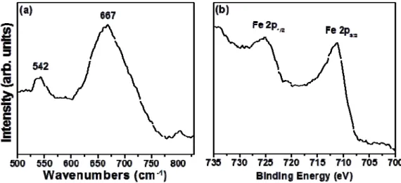
Figure 4.3 (a) The Raman spectroscopy analysis and (b) X-ray Photoelectron Spectrometer of
the iron oxide nanoparticles. ... 42
Figure 4.4 (a) Low angle powder x-ray diffraction patterns (XRD) of the MSN material and
Fe3O4 NPs capped on MSN (b) High angle powder x-ray diffraction patterns of
DMSA-Fe3O4 NPs and MSN@Fe3O4 nanocarriers. (c) Field-dependent
magnetization curve of Fe3O4 NPs, DMSA-Fe3O4 and MSN@Fe3O4 nanocarriers.
The inset shows that the MSN@Fe3O4 nanocarriers are attracted by an external
magnet. ... 43
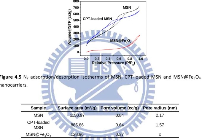
Figure 4.5 N2 adsorption/desorption isotherms of MSN, CPT-loaded MSN and MSN@Fe3O4
nanocarriers. ... 44
Figure 4.6 The Brunauer-Emmett-Teller (BET) analysis of MSN, CPT-loaded MSN and
xiii
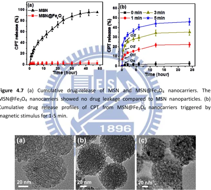
Figure 4.7 (a) Cumulative drug-release of MSN and MSN@Fe3O4 nanocarriers. The MSN
@Fe3O4 nanocarriers showed no drug leakage compared to MSN nanoparticles. (b)
Cumulative drug release profiles of CPT from MSN@Fe3O4 nanocarriers triggered
by magnetic stimulus for 1-5 min... 46
Figure 4.8 TEM images of nanostructures of MSN@Fe3O4 after magnetic stimulus for (a)
1-min (b) 3-min and (c) 5-min duration. ... 46
Figure 4.9 The weight loss (%), numbers and unoccupied surface area of Fe3O4 NPs on one
MSN@Fe3O4 nanocarriers surface under exposure to a magnetic stimulus for 0 to 5
min. ... 47
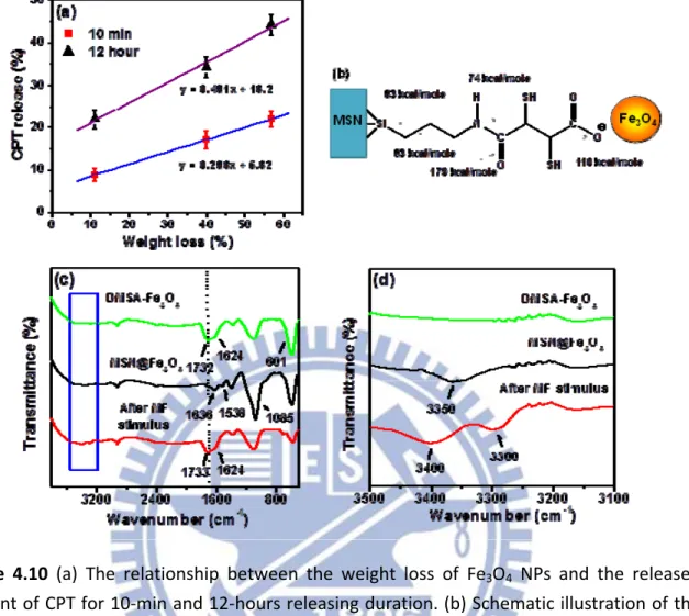
Figure 4.10 (a) The relationship between the weight loss of Fe3O4 NPs and the released
amount of CPT for 10-min and 12-hours releasing duration. (b) Schematic illustration of the chemical bonding between Fe3O4 NPs and MSN. (c) and (d) The
FT-IR spectrum of DMSA-Fe3O4 NPs,MSN@Fe3O4 and MSN@Fe3O4 after 3min
of magnetic stimulus. ... 49
Figure 4.11 Showing a linear relationship between the weight loss of Fe3O4 NPs and the
Fe3O4 NP unoccupied surface area of MSN. A similar relationship exists in between
the released amount of CPT and the Fe3O4 NPs unoccupied surface area of MSN for
10 min and 12 hours of release duration. ... 52
Figure 4.12 Time-course PL microscopy images of A549 cells labeled with FITC- MSN
@Fe3O4 nanocarriers and incubated for (a) 1 hour and (b) 4 hours. (c) Illustration of
the cell section after incubating for 4 hours. The cell skeleton was stained with rodamin phalloidin (red), and the cell nucleus with DAPI (blue). (d) Cell viability of A549 cells after 24 h of incubation with (1) control group, (2) MSN, (3) MSN@Fe3O4, (4) CPT-loaded MSN, (5) CPT-loaded MSN@Fe3O4, (6)
MSN@Fe3O4 for 3 min of magnetic stimulus, and (7) CPT-loaded MSN@Fe3O4 for
3 min of magnetic stimulus. Cell viability was measured using an MTT assay. ... 53
Figure 4.13 (a) T1-weighted and T2-weighted MR images (fast spin-echo sequence: repetition
time (TR) = 2500 ms, echo time (TE) = 33 ms) of the aqueous dispersion of MSN@Fe3O4 at different Fe concentrations. (b) T1 and T2 relaxation rates (1/T1,
1/T2) as a function of iron molar concentration obtained using a 7.0 T MR scanner.
... 54
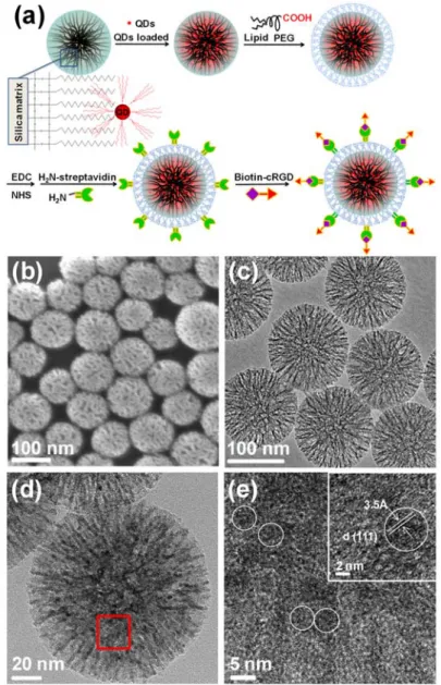
Figure 5.1 (a) Schematic illustration of the synthesis and structure of the cRGD-encoded lipid
coated quantum dots tagged porous nanobeads (cRGD-encoded LQNBs). (b) SEM image and (c) TEM image of porous nanobeads. (d) TEM image and (e) High resolution TEM image of QDs tagged porous nanobeads. The circles indicated the QDs. ... 61
Figure 5.2 The N2 adsorption/desorption isotherms of the nanobeads with Brunauer-Emmett-
Figure 5.3 The elemental mapping and energy-dispersive X-ray spectroscopy of the
incorporation of quantum dots (QNBs) by TEM. ... 62
Figure 5.4 (a) TEM and (c) fluorescence images of QDs tagged porous nanobeads without
surface modification and (b), (d) showed corresponding images of QDs tagged porous nanobeads which are surface modification of C18 hydrocarbon chain. ... 63
Figure 5.5 (a) The loading efficiency profiles of QDs tagged the nanobeads within the
soaking aqueous stock solution time by different emission of QDs. (b) The fluorescence spectrum, showing three separated peaks (530, 560, and 600 nm) with nearly equal intensities. The inset shows three distinguishable emission colors of QNBs excited with a near-UV lamp. (c) The quantum yield comparison of QNBs, with traditional surface coatings, QDs@SiO2, MUA-QDs, MPA-QDs and PEG-QDs
dispersed in PH 3.0, 5.0, 6.0, 7.4, 8.0 and 10.0. (d) TEM images of QNBs, QDs@SiO2, MUA-QDs, MPA-QDs and PEG-QDs. ... 64
Figure 5.6 The fluorescence data shows the supernatant of LQNBs dissolved in dilute water,
ethanol and butanol, which is in the absence of QDs in the solution. ... 66
Figure 5.7 (a) Schematic illustration of optical coding based on wavelength and intensity
multiplexing. (b) Seven distinguishable emission colors of QNBs excited with a near-UV lamp. From left to right (red to green), the emission maxima are located at 598, 586, 575, 558, 549, 541 and 532 nm. (c) Fluorescence images of nanobeads doped with single-color QDs emitting light at 530 (green), 560 (yellow), and 600 nm (orange-red). (d) Two kinds emitting light of LQNBs, green and red QDs, subcutaneously injected into a nude mouse. The left nude mouse is without injection. ... 68
Figure 5.8 (a) The cell uptake for incubation 2 h with cRGD-encoded LQNBs to MCF-7 and
HeLa cells. The cell nucleus is stained with DAPI (blue) and LQNBs emitted light at 530 nm (green). (b) Quantitative flow cytometric data shows that the fluorescence brightness and uniformity levels of cRGD-free and cRGD-encoded LQNBs uptake by MCF-7 and HeLa cells for incubation 2 h. (c) Flow cytometry analysis for the cRGD-encoded LQNBs accumulated in MCF-7 cells for incubation of 30 min, 1 h and 2 h. ... 69
Figure 5.9 (a) The cell uptake for incubation 2 h with cRGD-free LQNBs to MCF-7 and
HeLa cells. The cell nucleus is stained with DAPI (blue) and LQNBs emitted light at 530 nm (green). The CLSM images of cRGD-encoded LQNBs uptake with (b) MCF-7 cells and (c) HeLa cells. ... 70
Figure 5.10 Cell viability of MCF-7 cells after 24 h of incubation with nanobeads, QNBs, and
MPA-QDs. ... 71
Figure 5.11 (a) In vivo fluorescence imaging of nude mice bearing MCF-7 xenografts
xv
LQNBs in tumors. Total photon fluxes (TF) were determined at 0, 0.5, 1, 3 and 7 days using region-of-interest (ROI) measurement and expressed in photons/s. Color bar units are p/s/cm2/sr, where p is for photon and sr is for steradian. (b) The change in luminescence over time for cRGD-free and cRGD-encoded LQNBs. (c) Photographic images of several organs and xenograft tumor from sacrificing the nude mice after intravenously injection with cRGD-free and cRGD-encoded LQNBs for 1 and 3 days. The organs are heart (He), lung (Lu), liver (Li), spleen (Sp), kidneys (Ki) and tumor (Tu). ... 72
Figure 6.1 Schematic illustration of the synthesis and structure of the mesoporous silica
nanobeads with gold nanorods filled structure (AuRNBs). ... 78
Figure 6.2 (a) SEM image and (b) TEM image of porous nanobeads. (c) TEM image of the
gold seeds formed inside silica nanobeads (AuSNBs). (d) TEM image of mesoporous silica nanobeads with gold nanorods pore-filled structure (AuRNBs). (e) High resolution TEM image of mesoporous silica nanobeads gold nanorods pore-filled structure, which showed that lattice spacing of 1.44 Ǻ for Au nanorods (2 2 0) plane. (f) TEM image of well-defined AuRNBs after removing the silica matrix by sodium hydroxide (NaOH) etching. ... 79
Figure 6.3 The energy-dispersive X-ray spectroscopy of the mesoporous silica nanobeads
with gold nanorods pore-filled structure by TEM. ... 80
Figure 6.4 The N2 adsorption/desorption isotherms of the nanobeads with Brunauer-Emmett-
Teller (BET). The inset showed that the Barret-Joiner-Halenda (BJH) analysis of the nanobeads and AuRNBs. ... 81
Figure 6.5 (a) Extinction spectra of AuRNBs by controlling the aspect ratio during varying
the silver ion (AgNO3) content in the growth solution. (b) The longitudinal plasmon
maximum effect with different aspect ratio. (c) AuRNBs after removal of silica matrix... 82
Figure 6.6 Different aspect ratio of the AuRNBs. ... 83 Figure 6.7 Measured UV-Vis extinction spectra of (a) pure AuR and (b) AuRNBs before and
after irradiation with various laser pulses. ... 83
Figure 6.8 The proposed thermal transport processes from the nanoparticle to the environ-
ment and resulting temporal profiles of the temperature and the amplitude of the photoacoustic signal. ... 84
Figure 6.9 (a) Ultrasound and photoacoustic images of one vertical slice through the tumor.
The ultrasound images show the skin and tumor boundaries. Subtraction images were calculated as the 16 h post-injection image minus the pre-injection image. (b) Mice injected with AuRNBs showed a significantly higher photoacoustic signal than mice injected with pure AuR. ... 86
FITC-AuRNBs nanoprobes and incubated for (a) 4 hour and (b) 12 hours. The cell skeleton was stained with rodamin phalloidin (red), and the cell nucleus with DAPI (blue). (c) Quantitative flow cytometric data shows that the fluorescence brightness and uniformity levels of pure AuR and AuRNBs uptake by MDA-MB-231 for incubation 4 h and 12h. ... 87
Figure 6.11 (a) Before irradiation, cells incubated with AuRNBs. Live cells were stained with
clacein AM to appear in green. (b) After irradiation (808 nm for 2 min, in region left of the marker curve), essentially all cells were killed and the dead cells were stained with ethidium homodimer (EthD-1) to appear in red. (c) Cell viability of MDA-MB-231 cells after 24 h of incubation with nanobeads, AuSNBs, and AuRNBs. (d) Cell viability of MDA-MB-231 cells after 24 h of incubation with pure AuR and AuRNBs versus duration of irradiation. ... 88
Figure 6.12 (a) (b) (c) converting light absorption into heat by the photothermal effect of
AuRNBs and PBs, and infrared thermal mapping apparatus was used to monitor the temperature increasing when 808 nm NIR laser irradiated a MDA-MB-231 tumor-bearing nude mouse. (d) (e) (f) the MDA-MB-231 tumor-bearing nude mouse intravenously injected with AuRNBs solution and irradiated 2 min on the tumor site with NIR laser for pretreatment, treatment after 2 days and 14 days. (g) The volume of tumor variation by treated with NIR light. ... 90
Figure 7.1 Schematic illustration of the synthesis and structure of the magnetic mesoporous
silica nanobeads filled with gold nanorods structure (GRMNBs). ... 97
Figure 7.2 (a) TEM image of porous nanobeads. (b) TEM image of the tagged iron oxide
nanoparticles inside silica nanobeads (MNBs). (c) TEM image of magnetic mesoporous silica nanobeads filled with gold nanorods structure (GRMNBs). (d) High resolution TEM image of magnetic mesoporous silica nanobeads filled with gold nanorods structure. ... 97
Figure 7.3 The N2 adsorption/desorption isotherms of the nanobeads with Brunauer-Emmett-
Teller (BET). The inset showed that the Barret-Joiner-Halenda (BJH) analysis of the nanobeads and GRMNBs. ... 98
Figure 7.4 (a) Extinction spectra of NBs, MNBs and GRMNBs. Measured UV-Vis extinction
spectra of (b) pure AuR and (c) GRMNBs before and after irradiation with various laser fluences. ... 99
Figure 7.5 (a) Field-dependent magnetization curve of Fe3O4 NPs, MNBs and GRMNBs .
The inset shows that the MNBs and GRMNBs are attracted by an external magnet. (b) T1-weighted and T2-weighted MR images (7.0 T, fast spin-echo sequence:
repetition time (TR) = 2500 ms, echo time (TE) = 33 ms) of the aqueous dispersion of MSN@Fe3O4 at different Fe concentrations. (c) T1 and T2 relaxation rates (1/T1,
xvii
scanner. ... 101
Figure 7.6 The photoacoustic (PA) signal produced by GRMNBs is observed to be linearly
dependent on the concentration. ... 102
Figure 7.7 (a) Schematic diagram of the magnetic guided experimental set-up for
photoacoustic microscopy. (b) PA images in the phantom at different distance of pure AeR, GRMNBs and GRMNBs with an external magnet. ... 102
Figure 7.8 (a) PA image of tumor site with pre-injection. (b) Pa images of tumor site with
injected GRMNBs for 12 h. (c) PA images of different position slice through the tumor. Subtraction images were calculated as the 12 h post-injection image minus the pre-injection image. ... 103
Figure 7.9 (a) PA signal intensity of pure AuR, GRMNBs and GRMNBs with an external
magnet at different distances. (b) PA signal intensity of GRMNBs and GRMNBs with an external magnet in 12 h post-injection. ... 104
Figure 7.10 Time-course PL microscopy images of human stem cells labeled with FITC-
GRMNBs nanoprobes and incubated for (a) 8 hour and (b) 24 hours. Cellular retention of GRMNBs in stem cells cultured for different additional time of (c) 6 h (d) 24 h (e) 48 h. The cell skeleton was stained with rodamin phalloidin (red), and the cell nucleus with DAPI (blue). ... 106
Figure 7.11 (a) Schematic diagram of the magnetic guided experimental set-up under
magnetic remote-controlled stem cells. The image of (b) visible microscopy(c) fluorescent microscopy for distribution of stem cells under magnetic remote-controlled. ... 107
Figure 7.12 (a) (b) the MCAO modal mouse with setting an external magnet on the head. (c)
the brain tissue of MCAO modal mouse. (d) MR imaging for the stroke brain. ... 107
Chapter 1
Introduction
Nowhere in medicine are the goals of nanotechnology more hotly pursued than in the field of oncology. Researchers have created many examples of nanoparticles that can circulate through the bloodstream and stick to tumors. The optical or magnetic properties of some of these nanoparticles provide a means to image tumors at their earliest stages of development. Recently, nanometer-sized particulate systems are being developed as intravascular carriers to increase the levels of monitored agents delivered to targets, with the fewest side effects [1,2]. It is desirable that multiple nanocomponents with diagnostic and therapeutic functions can be integrated into a “single” nanosystem. These systems follow on the concept of a “theranostic” device, in which both diagnostic and therapeutic functions can be administered in a single dose. For example, anti-cancer medicine inhibit/kill cancer cells, superparamagnetic iron oxide nanoparticles improve the contrast of magnetic resnonance images (MRI) and magnetic remote-controlled, the quantum dots show fluorescence intensity signal can be seen by unaided eyes, and gold nanostructures improve the contrast of photoacoustic imaging (PA) and near-infrared light therapy. Recently, many studies have been reported in multifunctional nanostructures, such as self-assemble nanoparticles(drugs)/polymer [3-5], material surface-coating metal particles [6-8], and chemical covalent bridge drugs[9,10]. However, such a manner of the nanocomponents may change or decrease the property of the functionalized nanoparticles. For example, optical probes such as quantum dots coated by silica, copolymer or lipids demonstrated a great damage of quantum yield approximately 30-50% lower than their original brightness, limiting their applications. Furthermore, most chemical modifications are complex, time-consuming and even in a risk of losing original function of
2
the starting nanomatrix. Therefore, a practical development of desired nanocomponents with coupled functionalities will enable new imaging modes available from each individual component for diagnostic and therapeutic specificity.
More recently, many studies have highlighted an important class of nanocarriers made of a mesoporous silica matrix, such as MCM-41, where therapeutic or biologically active molecules can be filled and anchored into the nanopores of the silica nanoparticles, followed by a subsequent free-diffusion release from the nanopores after administration to the site of disease [11-16]. On the other hand, the MCM-41 type mesoporous silica has several attractive features, such as a stable mesoporous structure, large surface area, tunable pore size and volume, and well-defined surface properties. Therefore, combining different nanostructured materials will enable the development of multifunctional nanomedical platforms for diagnostic and therapeutic. However, using MCM-41 type mesoporous silica matrix with pore size about 2~3 nm to load guest molecules by chemical bridge, it will limit tagged large molecule weight molecules or particles and damage the property through chemical bridge [17,
18]. Thus, the development of multifunctional large pore size nanoprobes, meaning more
capacity for guest molecules, enabling new imaging modalities beyond the intrinsic limitations of individual components is essential. Several important issues on mesoporous-based multifunctional carriers for diagnostic and therapeutic still need to be further addressed.
First, in order to combine functionality with magnetic resonance (MR) imaging capability and drug-carrying functions, we synthesized a new drug-release nanosystem in Chapter 4, which is constructed by chemically capping Fe3O4 nanoparticles onto the surface
of a MCM-41 type mesoporous silica, while drug molecules (here we used a dye molecule (FITC) and an anticancer drug, (S)-(+)-Camptothecin (CPT)) were encapsulated into the pores. An external high frequency magnetic field (HFMF) trigger can be used to remove the Fe3O4
and then subsequently lead a fast-responsive drug release for cancer therapy.
Next, in Chapter 5, we shifted our focus on large pore size (about 10~15nm) mesoporous nanocarriers which were designed and prepared by a highly hydrophobic octadecyltrimethoxysilane-modified mesoporous silica nanoparticle (hydrophobic porous nanobeads) with pore size greater than 10 nm. Furthermore, with hydrophobic QDs encapsulated into hydrophobic porous nanobeads and the peptide cRGD bridged on the surface of QD-tagged nanobeads by using noncovalent biotin-streptavidin link, a potential cellular-based targeting is achievable and exhibits significantly increased αvβ3-expressing cell
targeting toward MCF-7 breast cancer cells over the αvβ3-low expressing in HeLa cervix
cancer cells, indicating a successful design of highly-cytocompatible nanoparticulate platform capable of providing cell-specific targeting and nano-imaging modalities for biomedical applications.
To combine the diagnostic and therapeutic functions, we employed the gold nanorods to form a novel nano-seaurchin structure which is characteristic of high-density and well-dispersive gold nanorods in one mesoporous silica nanobead (AuRNBs) (Chapter 6). The AuRNBs showed increased photothermal stability and retained their superior optical properties under much higher fluence laser pulses at 10 mJ/cm2. The AuRNBs also provided a stable photoacoustic signal and highly efficient hyperthermia effect both in vitro and in vivo, indicating a powerful theranostic modality.
To be continued, in Chapter 7, base on the nano-seaurchin structure nanoprobes, the multifunctional nanodevice were fabricated by intergrating homing stem cells, photoacoustic imaging, MRI imaging and magnetic remote-controlled. The nanoprobes (GRMNBs) is composed of mesoporous silica nanobeads tagged iron oxides nanoparticles, where the nanoporosity was further filled with gold nanorods, giving a multifunctional nanoprobe that can be controlled by external magnetic navigation, capable of performing MR and photoacoustic imaging modalities simultaneously. The GRMNBs showed the significant
4
contrast enhancement for PA signal with the presence of external magnet as compared with pure gold nanorods. This multifunctional nanoprobes with magnetically controllable nature and dual contrast modality offer great advantages for carrying/homing stem cell, therapeutic delivery and real-time detection/diagnosis.
We make a conclusion in Chapter 8 for each part of our nanoprobes with diagnostic and therapeutic functions. These nanoprobes are simultaneously being multifunctional, compact in size, and sensitive to environmental. Future development of this new class of multifunctional nanoprobes includes diagnostic and therapeutic in biological and medical fields, and will lead to a new biomedical nanotechnology. Numerous cancer or other disease-related deaths could be averted in the near future, and our lives will be finally shaped by the advances and developments in the field.
Chapter 2
Literature Review and Theory
2.1 Introduction of nanosystems for detection and treatment of diseases
Development of multifunctional nanosystems is one of the most rapidly advancing
areas of science in which material and chemical researchers are contributing to human health care. The nanosystems have typically focused on imaging enhancement, compounds delivery and site-specific targeting, which separate the function for each independent part. Currently, the new multifunctional nanosystems have considerable effort to incorporate both diagnostic and therapeutic functions into a “single” nanoscale device. The technique can achieve such dual functions, particularly combining the imaging detection and disease treatment. The key concept of the new nanosystems is “theranostic” device, in which both diagnostic and therapeutic integrated into a single nanosystem. For designing functional nanoparticles, one advantage of combining imaging with therapeutic functions is that can be monitored the biodistribution of nanosystems in vivo, reducing the unintended side effect and physical or chemical damage in health tissues [19,20]. By these wide advantages of theranostic system, a number of researches have been successfully proposed to integrate active drug molecules, optical or magnetic nanoparticles and host materials, where to manipulate theranostic desirably. For example, different structural nanocomponents as host materials have been used to introduce the guest materials such as drugs, protein and funcational nanoparticles [21-26]. As shown in Figure 2.1, the nanosystems contain both structural (therapeutic) and functional (diagnostic) nanocomponents. For the therapeutic nanocomponents, the structural nanocomponents such as liposome [27, 28], micelle [29, 30], porous silica [31-33], and polymer [34, 35] can be host materials for carrying drugs cargo, while gold and carbon nanostructure enable photothermal therapy. For the diagnostic nanocomponents, the functional nanocomponents such as gold nanostructures (for optical imaging), quantum dots (for fluorescence imaging)
6
and magnetic nanocrystal (for MRI imaging and magnetic guiding) can be guest materials for incorporating into the inner space or equipping on the surface of host materials. This literature reviews exhibit the theranostic nanosystems including mesoporous silica nanoparticles in which the functional materials such as quantum dots, iron oxides, or gold nanostructures incorporating/equipping for imaging, diagnosis, photo-absorbing or triggering drug release. In the later sections of this review, we focus on the current applications of nanotechnology for silica nanoparticles, especially for the tumor treatment and stem cell therapy.
Figure 2.1 The nanosystems design strategies for containing both therapeutic and diagnostic
nanocomponents.
2.2 Remote-controlled mesoporous silica nanoparticles for drug delivery
The unique properties of mesoporous silica materials, such as stable mesoporous structures, high surface areas ( >800m2g-1), uniform tunable pore sizes (2-10 nm in diameter) and volumes, easy surface modification and good biocompatibility have made them ideal for hosting molecules of various sizes, shapes, and functionalities. Due to high surface areas property, the mesoporous silica materials have been developed for controlled-release delivery of drug, biocides, genes, or even proteins in vitro or in vivo [36-38]. A major key point for mesoporous silica materials as drug delivery is most hydrophobic therapeutic anticancer drugs as low solubility in aqueous media hampers the ability of drugs to be administered through the intravenous route. The mesoporous silica materials have large surface areas and porous
Component Nanoparticle type Function
Structural (therapeutic) nanocomponent
Liposome, micelle, porous
silica, and virus Drug delivery Gold and carbon
nanostructure Photothermal therapy Functional
(diagnostic) nanocomponent
Gold nanostructure and
quantum dots Optical imaging Magnetic nanocrystal Magnetic guiding
interiors that can be used as reservoirs for storing hydrophobic drugs. Unlike polymer-based nanoparticles, these robust inorganic materials can tolerate many organic solvents. In addition, remote-controlled drug delivery can improve the efficiency of chemotherapy by allowing the maximum fraction of the delivered drug molecule to react with the disease sites without adverse effects on the normal cells. Therefore, the development of a desired drug carrier for medical applications should possess remote-controlled properties as well as real-time responsiveness to the stimuli, for example, when urgent disease control measures and/or a slow, sustained release to meet different clinical applications are required.
2.2.1 Synthesis of mesoporous silica nanoparticles
The development of porous materials with large specific surface areas is currently an area of extensive research, particularly with regard to potential applications in areas such as adsorption, chromatography, catalysis, sensor technology, and gas storage. An upsurge began in 1992 with the development by the Mobil Oil Company of the class of periodic mesoporous silicas known as the M41S phase. These materials superseded zeolite molecular sieves, which were restricted to a pore size of around 1.5 nm. Like the microporous crystalline zeolites, this class of materials is characterized by very large specific surface areas, ordered pore systems, and well-defined pore radius distributions. Unlike the zeolites, however, the M41S materials have pore diameters from approximately 2 to 10 nm and exhibit amorphous pore walls. The most well-known representatives of this class include the silica solids MCM-41 (with a hexagonal arrangement of the mesopores, space group p6mm), MCM-48 (with a cubic arrangement of the mesopores, space group Ia3d), and MCM-50 (with a laminar structure, space group p2) (Figure 2.2). The use of supramolecular aggregates of ionic surfactants (long-chain alkyltrimethylammonium halides) as structure-directing agents (SDAs) was groundbreaking in the synthesis of these materials. These SDAs, in the form of a lyotropic liquid-crystalline phase, lead to the assembly of an ordered mesostructured composite during
8
the condensation of the silica precursors under basic conditions. The mesoporous materials are obtained by subsequent removal of the surfactant by extraction or calcination.
Figure 2.2 Structures of mesoporous M41S materials: (a) MCM‐41, (b) MCM‐48 and (c)
MCM‐50 type. [39] Copyright 2006, Wiley‐Vch.
In-depth investigations into the formation process of these composite materials have found that two different mechanisms are involved: On the one hand, in true liquid-crystal templating (TLCT), the concentration of the surfactant is so high that under the prevailing conditions (temperature, pH) a lyotropic liquid-crystalline phase is formed without requiring the presence of the precursor inorganic framework materials (normally tetraethyl- (TEOS) or tetramethylorthosilica (TMOS)).[40] On the other hand, it is also possible that this phase forms even at lower concentrations of surfactant molecules, for example, when there is cooperative selfassembly of the SDA and the already added inorganic species, in which case a liquid-crystal phase with hexagonal, cubic, or laminar arrangement can develop (Figure 2.3)
One of the major applications of mesoporous silica materials is in biomedicine. Appling the porous materials to drug delivery system, it may be possible to achieve improving delivery of poorly water-soluble drugs and delivery of large macromolecule drugs. However, for general MCM type mesoporous silica materials, the pore size are about 2~4 nm in diameter, which is too small to load large molecules/drugs and amount of molecules/drugs, limiting biomedicine applications. Therefore, many methods have been reported for controlling the periodic unit size and pore size of mesoporous materials. The most commonly used technique is the introduction of a “swelling agent” into the structure directing template.
Commonly used swelling agents include the large organic hydrocarbons such as dodecane, 1,3,5-trimethylbenzene, triisopropylbenzene,and tertiary amines. The introduction of these agents has been shown to lead to pore expansion by up to 30%, but loss of long-range order of the mesoporous structure is commonly observed.
Figure 2.3 Formation of mesoporous materials by structure‐directing agents: a) true
liquid‐crystal template mechanism, b) cooperative liquidcrystal template mechanism. Copyright 2006, Wiley‐Vch.
Figure 2.4 Formation of mesoporous materials by using hydrolytic condensation of
tetraorthosilicate (TEOS) and polymerization of styrene into polystyrene (PS). Copyright 2008, Elsevier Inc.
10
Smarsly et al. [41] and Ryan et al. [42] recently reported a method of mixing surfactant blends to tailor the pore size of mesoporous silicas, showing Angstrom-level control over the pore size. However, the longest block copolymer surfactant chain used governs the largest pore size obtainable with this method. In order to solve these problem, Nandiyanto et al. [43] develop a method for the preparation of spherical nano-sized silica particles with a tunable pore size ranging from 4 to 15 nm and a tunable particle size in nanometer range (20–80 nm) using an organic template method in a water/oil phase. (Figure 2.4) In briefly, using hydrolytic condensation of tetraorthosilicate (TEOS) and polymerization of styrene into polystyrene (PS) grows silica nanoparticles. The process uses an amino acid as the catalyst, octane as the hydrophobic supporting reaction component, and cetyltrimethylammonium bromide (CTAB) as the surfactant. The reactions took place simultaneously in the micelle, resulting in a composite silica/PS particle with CTAB as the as-prepared product. In the final step, the organic components (CTAB and PS) were removed by calcination to yield the mesoporous silica particles. Thus, the mesoporous silica materials can be potential of biomedicine applications by using this synthesized method.
2.2.2Nanoparticles cap porous silica nanoparticles for drug delivery
Recent reports [44, 45] on the design of capped and gated mesoporous silica derivatives have shown promise in the generation of controlled-release nanodevices. Mesoporous silica nanoparticles that are capable of stimuli-responsive release of cargo molecules are presently under active investigation. A key challenge for these integrated systems is whether they can be designed for biological use through autonomously controlled nanovalve opening inside cells of interest. Many important site-selective deliveries, e.g., deliveries of highly toxic antitumor drugs, such as Taxol, require “zero release” before reaching the targeted cells or tissues. However, the release of encapsulated compounds of many current drug delivery systems typically takes place immediately upon dispersion of the drug/carrier composites in
water. Also, the release mechanism of many biodegradable polymer-based drug delivery systems relies on the hydrolysis-induced erosion of the carrier structure. Such systems typically require the use of organic solvents for drug loading, which could sometimes trigger undesirable modifications of the structure or function or both of the encapsulated molecules, such as protein denaturation and aggregation. Therefore, designing a stimuli-responsive and capable of “zero premature release” for controlled release systems is required.
Figure 2.5 Schematic representation of the CdS nanoparticle‐capped MSN based
drug/neurotransmitter delivery system. The controlled‐release mechanism of the system is based on chemical reduction of the disulfide linkage between the CdS caps and the MSN hosts. Copyright 2003, American Chemical Society.
12
controlled-release delivery system that is stimuli-responsive and chemically inert to the matrixentrapped compounds. The major concept of this designed is using CdS nanoparticles to cap on the surface of mesoporous silica nanoparticles for preventing the drug in the pore releasing in nature. Furthermore, the controlled-release mechanism of the system is based on isulfide linkages between the MSNs and the CdS nanoparticles are chemically labile in nature and can be cleaved with various disulfide-reducing agents, such as dithiothreitol (DTT) and mercaptoethanol (ME). As shown in Figure 2.5, the release of the CdS nanoparticle caps from the drug/neurotransmitter-loaded MSNs can be regulated by introducing various amounts of release triggers. The functionalized MCM-41 type of mesoporous silica nanosphere material can be used as novel controlled-release delivery carriers that are stimuli responsive.
2.2.3 Responsive molecules with mesoporous silica nanoparticles for drug delivery
The goal of drug delivery is to administer medicinally active molecules with high specificity to diseased cells in a targeted and controlled manner. Recently, mesoporous silica nanoparticles have emerged as an appealing class of drug delivery vehicles for the treatment of diseases on account of their sophisticated design and mode of action. The size and shape of the mesoporous silica nanoparticles can be tuned to maximize cellular uptake, while the dimensions and physical environment of the nanopores inside the nanoparticles can be tailored to store a range of small molecules of different sizes. In particular, the silica nanoparticles can be covered and mechanized with a monolayer of nanovalves3k and other artificial molecular and supramolecular machines in order to convert them into smart drug delivery vehicles, that is, mesoporous silica nanoparticles capable of storing and releasing drug molecules on command in response to external stimuli such as pH and/or redox changes, irradiation with light, or the action of enzymes. As shown in Figure 2.6, Park et al. [47] employed the functional mesoporous silica nanoparticles that are composed of the surface
cyclodextrin (CD) gatekeepers, functional stalks, and fluorescence probes within porous channels as an enzyme-responsive nanocontainer. The torus shaped CD was initially chosen to block the porous channel of mesoporous silica nanoparticles. The CD moiety of the gatekeeper can be hydrolyzed by α-amylase, and the stalk part was designed to be degraded by lipase to exhibit enzyme-responsive characteristics in the release of guests. This system would provide diverse applications in controlled drugs delivery.
Figure 2.6 (A) Synthetic route to Si‐MP‐CD: (1) 3‐aminopropyltriethoxysilane; (2) succinic
anhydride and triethylamine; (3) removal of CTAB, calcein, CuSO4, sodium ascorbate, and mono‐6‐azido‐_‐CD. (B) FE‐SEM image of Si‐MP‐CD. (C) The structure of surface functional motifs on Si‐ MP‐NBE‐CD. (D) Schematic illustration for enzyme‐triggered release of guest molecules from the pore of CD‐covered nanocontainers. Copyright 2009, American Chemical Society.
2.3 Gold nanostructure for biomedical applications
The gold nanostructures have been a subject of intensive research for their fascinating
(A)
14
surface plasmon resonance (SPR) property which is an optical phenomenon arising from the interaction between an electromagnetic wave and the conduction electrons in a metal. Under the irradiation of light, the conduction electrons in a gold nanostructure are driven by the electric field to collectively oscillate at a resonant frequency relative to the lattice of positive ions. At this resonant frequency, the incident light is absorbed by the nanostructure. Due to this SPR property, gold nanostructures have found use in a rich variety of applications such as (1) Surface-enhanced Raman scattering (SERS). (2) Photoacoustic imaging. (3) Photothermal treatment. The remarkable SPR properties and biocompatibility of gold nanostructures make them promising both as a contrast agent for in vivo optical imaging, and as a therapeutic agent for photothermal treatment of cancer for biomedical applications.
2.3.1 Synthesis of gold nanostructure
Gold nanostructures have proven to be a versatile platform for a broad range of biomedical applications, with potential use in numerous areas including: diagnostics and sensing, in vitro and in vivo imaging, and therapeutic techniques [48-50]. These applications are possible because of the highly favorable properties of gold nanostructures, many of which can be tailored for specific applications. In 1857, Michael Faraday demonstrated the synthesis of gold colloids in an aqueous medium and Gustav Mie solved Maxwell’s equations for spherical particles, making it possible to predict and explain the optical properties of gold nanospheres. Furthermore, in 1951, John Turkevich provided a robust and simple synthesis method [51]. In 1973, Frens systematically developed methods for synthesizing gold nanospheres of varying diameter by citrate-mediated reduction [52]. The resulting nanoparticle sizes are largely governed by the stoichiometric ratio of gold to the reducing agent with larger ratios leading to larger diameters. One of the most interesting and powerful properties of gold nanostructures is localized surface plasmon resonance (LSPR) which is the origin of many of the new applications of nanoscale gold nanostructures. When a gold nanostructure encounters
electromagnetic radiation of an appropriate wavelength, the delocalized conduction electrons of the metal will begin to oscillate collectively relative to the lattice of positive nuclei with the frequency of the incoming light (Figure 2.7a). This process can be divided into two types of interactions: scattering, in which the incoming light is re-radiated at the same wavelength in all directions, and absorption, in which the energy is transferred into vibrations of the lattice (i.e., phonons), typically observed as heat. Together, these processes are referred to as extinction (extinction = absorption + scattering).
Gold nanospheres (Figure 2.7b) are the simplest structure to synthesize, and there are
now well-developed techniques to produce particles of high uniformity with a variety of sizes. In a typical reaction, a dissolved gold salt (such as HAuCl4) is reduced to gold atoms in the
presence of a capping agent or surfactant to prevent aggregation. In the most commonly used method, the reducing agent and capping agent are the same: citrate ions. Depending on the size of the nanosphere, strong LSPR extinction will occur between 500–600 nm. Nanoshells (Figure 2.7c) are created by depositing small gold nanoparticles onto the surface of a silica sphere, followed by deposition of more gold through chemical reduction. The LSPR of gold nanoshells and gold nanocages can also be tuned into the NIR by adjusting the thickness of gold walls surrounding a dielectric or hollow core which depends on the ratio between the diameter of the particle (typically ~120 nm), and the thickness (~10 nm) of the deposited gold layer. For gold nanorods (Figure 2.7d), these structures are typically synthesized by a seed-mediated, solution-phase method, where small gold seeds are added to a series of growth solutions. Typically, gold nanorods have two LSPR peaks, one for the transverse mode around 515 nm and the other for the longitudinal mode whose position depends strongly on the aspect ratio of the rod. By adjusting the synthesis parameters (e.g., the concentrations of key reagents and the size of the initial gold seeds), it is possible to synthesize nanorods with strong LSPR-based absorption across the visible spectrum and into the NIR. For the gold nanocage (Figure 2.7e), the gold nanocages are created by hollowing out the interior of a
16
Figure 2.7 (a) Localized surface plasmon resonance (LSPR) is another critical property of gold
nanostructures that results from the collective oscillation of delocalized electrons in response to an external electric field. (b) multiply twinned gold nanoparticles. (c) gold nanoshells (silica beads coated with a polycrystalline gold layer). (d) gold nanorods, and (e) gold nanocages. [53] Copyright 2011, Royal Society of Chemistry.
sacrificial template of silver nanocubes (as well as silver nanocrystals with other shapes). When silver nanocubes are titrated with a gold salt (typically HAuCl4), a galvanic
replacement reaction occurs, causing gold atoms to be deposited on the surface of the nanocube and silver atoms to be dissolved from a small pit in the surface.
2.3.2 Photoacoustic imaging for gold nanostructure
Recently, several commercially available optical imaging, such as confocal microscopy, two-photon microscopy and optical coherence tomography, have been successful, but none of
(a)
(d)
(b)
(c)
these technologies can provide penetration beyond ~1mm into scattering biological tissues due to relying on ballistic and qusi-ballistic photons. Photoacoustic imaging, which combines high ultrasonic resolution and strong optical contrast in single modality, has broken through this limitation. Thus, many researchers have interesting in the field of photoacoustic imaging in the past few years. In 1880, Alexander Graham Bell was first reported the photoacoustic effect as a physical phenomenon. However, the photoacoustic imaging technology was developed only after the advent of ultrasonic transducers, computers and lasers [54]. In 2000s, Wang. et al. [55, 56] introduced the fundamentals of photoacoustic imaging technology to lead the generation of this technology development. In photoacoustic imaging, the intensity modulated electromagnetic radiation, e.g., a beam of pulsed laser light, is directed at the imaging target. The light absorbed and converted to an outgoing thermoacoustic wave can be detected by an ultrasound transducer and used to reconstruct images (Figure 2.8). Key factors for photoacoustic imaging efficiency are how many incident photons can be absorbed and converted to heat, and how fast generated heat can diffuse out from the target during thermoelastic expansion and wave generation. In order to enhance the photoacoustic imaging signal, the probes used for photoacoustic imaging should be minimally emissive, enhancing conversion of absorbed light energy to heat and subsequently to an acoustic signal. In recent studies, the photoacoustic imaging has been demonstrated successfully using gold nanorods, nanocages, and nanoshells with high and tunable optical absorption cross section. Lihong V. Wang and Younan Xia were reported a new theranostic system with the contrast of photoacoustic imaging and control the release of a chemical or biological effector by high-intensity focused ultrasound (HIFU) [57]. They facile and versatile strategy for loading hydrophobic or hydrophilic drugs into the hollow gold nanocages and use a phase-change material to control the release of drug in response to temperature increase.
18
Figure 2.8 Photoacoustic microscopy (PAM) system. Copyright 2008, IEEE.
Recently, Chen et al. introduced a new approach to significantly increase the
contrast-to-noise ratio (CNR) of contrast-enhanced nanoparticle augmented photoacoustic imaging by encapsulating gold nanorods within an optically nonabsorbing shell silica material. The role of the silica shell in amplifying the photoacoustic signal highlights the importance of the heat transfer mechanism from the gold nanoparticle to the ambient signal-generating medium. They used the cetyltrimethylammonium bromide (CTAB) stabilized gold nanorods, furthermore, CTAB was replaced by mPEG-thiol through ligand exchange, and then silica was grown onto the PEGylated gold nanorods via the modified Stober method using tetraethyl orthosilicate (TEOS). In addition, it can control the silica thickness with conformal and isotropic silica coating of the gold nanorods (Figure 2.9). To discuss the photoacoustic imaging enhancement, the author showed a comparison of ultrasound, photoacoustic, and the spatially coregistered combined ultrasonic and photoacoustic images of phantoms with inclusions containing PEGylated gold nanorods, and gold-silica core shell nanorods with silica shells of 6, 20, and 75 nm thickness, respectively. The PEGylated gold nanorods produced a much weaker photoacoustic signal than that with silica-coated nanorods. As the thickness of the silica shell increases from 6 to 20 nm, the photoacoustic signal increases and, consequently, the photoacoustic image showed brighter. The signal enhancement is slightly
reduced for the nanorods with a 75 nm silica shell (Figure 2.9e). As a result, silica coating of gold nanoparticles appears to be a simple way to increase their usefulness as contrast agents for photoacoustic imaging.
Figure 2.9 (a) TEM image of PEGylated gold nanorods. TEM images of gold‐silica core‐shell
nanorods with (b) 6 nm, (c) 20 nm. (d) 75nm thichness of silica coating.(e) ultrasound, photoacoustic and combined ultrasound and photoacoustic images of PEGylated gold nanorods and gold‐silica core‐shell nanorods with 6 nm, 20 nm and 75 nm silica coating. [58] Copyright 2011, American Chemical Society.
2.3.3 Gold nanostructures integrate with silica for phtothermal therapy
Recently, near-infrared (NIR) light absorbing plasmonic nanomaterials have attracted intensive attention for their hyperthermia therapy to kill tumorigenic cells without damaging normal cellsm such as gold nanorods, gold nanocages, gold nanoshells and many gold nanocomposites. Here, Liu et al. presented a kind of PEG functionalized gold nanoshells on silica nanorattles for ablation of breast tumor (Figure 2.10). They emphasized that the gold nanoshells on silica nanorattles demonstrate positively result for in vivo breast tumors in mice show complete regression by the combination of selectively targeting, photothermal therapy and chemotherapy via a single irradiation with NIR laser light. In briefly, the gold nanoshell was consists of a thin gold nanoshell and a mondispersed mesoporous silica nanoparticle core. After that procedure, the Methoxy-poly(ethylene glycol)-thiol (mPEG-SH) was attached to the gold via the thiol end groups. Furthermore, the Transferrin (Tf) was also linked to gold
20
silica nanorattles (GSNs) because the carboxylic end of gold silica nanorattles reacted with amine groups on the transferrin via carbodiimide chemistry to form an amide bond. For the photothermal therapy test, an infrared thermal mapping apparatus was used to monitor the temperature increasing when an 808 nm NIR laser light irradiated a MCF-7 tumor-bearing BALB/c nude mouse ( < 5 mm × 5 mm). The mouse was intravenously injected with pGSNs-Tf saline solution (200µL, 1 mg mL-1). Then it was anesthetized with sodium pentobarbital and irradiated the tumor region with NIR light (2 W cm-2) at 6 h post-injection. As a result, during this irradiation, the temperature of the tumor bviously increased from 30.5 ° C to 45.7 ° C in the focal region to kill the cancer cells. This proves that pGSNs-Tf is promising as an ideal photothermal converter in cancer therapy.
Figure 2.10 (a) Schematic diagram and TEM image of GSNs synthesis and bioconjugation. (b)
The photo image of a MCF‐7 tumor‐bearing BALB/c nude mouse under an 808 nm NIR laser light irradiation. [59] Copyright 2012, Wiley‐Vch.
2.4 Magnetic nanoparticles for biomedical applications
Controlled drug release from nanofunctional materials, especially magnetic nanoparticles,
is attracting increasing attention due to their potentials in cancer therapy and treatment of other ailments. The magnetic nanoparticles stems from intrinsic properties of their magnetic properties combined with their drug loading capability and the biochemical properties that can be bestowed on them by mean of a suitable coating [60]. Preparation methods of NPs generally fall into the category of so-called “bottom up” method, where nanomaterials are prepared