4048 IEEE TRANSACTIONS ON MAGNETICS, VOL. 43, NO. 11, NOVEMBER 2007
Output Feedback Sliding Mode Control for a Linear Focusing
Actuator in Digital Video Cameras
Hsing-Cheng Yu
1;2and T. S. Liu
1Department of Mechanical Engineering, National Chiao Tung University, Hsinchu 30010, Taiwan, R.O.C. Electronics and Opto-electronics Research Laboratories, Industrial Technology Research Institute,
Hsinchu 31040, Taiwan, R.O.C.
The output feedback sliding mode control offers an effective positioning method by robustness to parameter variation and distur-bance rejection. This paper presents the output feedback sliding mode control based on a position estimation algorithm written in the microprocessor for use in the focusing control system of a digital video camera to achieve fast focusing response and accurate positioning despite vibration and friction of the movable part of the linear focusing actuator. The focusing performance by utilizing the output feed-back sliding mode control includes a 60-ms setting time and 7- m steady-state error, respectively, which are only half and one-third of those in proportional-integral-derivative control when the movable part of the linear focusing actuator moves at a 5-mm stroke.
Index Terms—Digital video camera (DVC), focusing, linear actuator, sliding mode control (SMC).
I. INTRODUCTION
A
S focusing and zooming actuators, stepping motors (SPMs) are extensively adopted in digital video cameras (DVCs). Following rising consumer demand for DVCs in electronic product markets, enhanced properties and advanced functions play an increasingly pivotal role in luring new cus-tomers. A portable DVC emphasizes ingenious designs, power savings, high-quality charged coupled device (CCD) images, and fast focusing speeds to satisfy consumer demand. SPMs represent conventional focusing actuators in DVCs, but their focusing responses in open-loop control are about 400 ms, which are slower than linear focusing actuators (LFAs). As a result, the slow focusing speed of SPMs in DVCs causes high power loss and low efficiency. Additionally, noise interference arising from SPMs in DVCs is easily recorded into the digital films during focusing operation, whereas not when using LFAs in DVCs. Moreover, SPMs are limited in terms of their fixed resolution, possibly incurring errors when using open-loop con-trol during focusing. Such limitations hinder us from obtaining clear CCD images in DVCs. Furthermore, not only are SPM structures more complex than LFAs, but also the SPM size is larger than an LFA. Therefore, for the use in DVCs, the LFA represents a promising alternative to SPMs.Several works concerning LFAs in DVCs have been ex-tensively studied. A design method of LFA was presented [1] to achieve low battery consumption and high operational efficiency. Additionally, a proportional-integral controller was adopted for a focusing control in DVCs [2] but lacked robust-ness to compensate for nonuniform friction and disturbance during focusing. The above literature emphasized mainly the LFA design and used the most common control rule to position in DVCs. Therefore, this paper presents the output feedback sliding mode control (OFSMC) based on a position estimation algorithm (PEA) to achieve fast focusing time and accurate positioning despite vibration and friction of the LFA in DVCs.
II. FOCUSINGCONTROLMECHANISM ANDMODEL
For fast focusing control and access capability, the computer-aided manufacturing structure and experimental prototype of
Digital Object Identifier 10.1109/TMAG.2007.893299
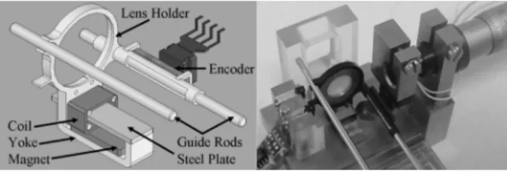
Fig. 1. Structure of a linear focusing actuator in a DVC.
LFA consists of a movable part and a stationary base as shown in Fig. 1. A movable part comprises a lens holder, a coil, and a linear magnetic strip mounted on a side of tube; moreover, a sta-tionary base includes a permanent magnet, a yoke, a steel plate, and two guide rods which maintain its moving trajectory of a movable part to avoid twisting. A position encoder consists of a magneto-resistive (MR) sensor and a linear magnetic strip with 0.88-mm polar pitch and is then adopted to acquire position of a movable part of a LFA in a DVC during focusing. The transfer function of the designed LFA can be obtained to form dynamic equations by Laplace transform. It relates the control voltage
to the displacement, based on the PEA , in domain written as
(1) where the force constant Nt/A, the coil
induc-tance H, the coil resistance , the
mass of the movable part is 1.8 10 kg, and the damping ratio Nt/(m/s) is from measurement results. The focusing model of the LFA in (1) can be rewritten in state variables form as
(2)
where the system state vector is the
control voltage, is the focusing displacement, and the
YU AND LIU: OUTPUT FEEDBACK SLIDING MODE CONTROL FOR A LINEAR FOCUSING ACTUATOR IN DIGITAL VIDEO CAMERAS 4049
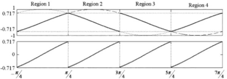
Fig. 2. Four independent regions from comparing two periodic sinusoids.
disturbance vector caused by system uncertainty and external disturbance is bounded by
(3) and is a known boundary function.
III. POSITIONESTIMATIONALGORITHM(PEA)
The PEA uses position encoder outputs to determine the ac-curate focusing position of a movable part in the LFA. When the movable part of the LFA moves between two photo-interrupters and causes a relative displacement between an MR sensor and a linear magnetic strip, two sinusoidal signals are generated
(4) (5) where is the electrical angle, and offsets of two sinusoidal signals are
(6) Furthermore, the intensity of two sinusoidal signals is
(7) Thus, the normalized form of and can be obtained as (8) (9) Two sinusoidal signals in a period can be divided into four in-dependent regions with multipliers of as delimits; the values of in region 1 ( to ) and region 3 ( to ) are within 0.7071 and 0.7071, so are those of in region 2 ( to ) and region 4 ( to ). Each region cor-responds to a quarter of the 0.88-mm polar pitch of the position encoder, where values of and can be approximated by linear regression without the displacement error about 3 m. The displacement of the movable part of the LFA can be de-termined as
(10) where are the numbers of region that an LFA has passed
and denotes values of or for the in
regions 1 to 4, respectively, as shown in Fig. 2. Accordingly, the displacement of the movable part in the LFA can be determined during focusing.
Fig. 3. Block diagram of PID control method for focusing.
IV. SERVOCONTROLMETHOD
Proportional-integral-derivative (PID) control is the most common and useful servo method. Hence, the block diagram of focusing control system including two-loop PID controller is shown in Fig. 3. The controller for displacement and velocity is written as [3]
(11) where is the command output; , and are con-stants for PID control; and is the error between the com-mand output and the measured output.
The OFSMC offers an effective position method with insen-sitivity to parameter variations and disturbance rejection capa-bility. The LFA has to undergo a desired displacement during focusing to obtain clear CCD images immediately. The output displacement error can be defined as a system state, where is the actual displacement obtained from PEA. Thus, in OFSMC, the sliding function is prescribed in terms of error terms [4]
(12) where coefficients , and are determined from the sliding mode conjugate poles and
as
(13) The OFSMC has to stabilize the focusing control system to move forward and stay on the sliding surface , i.e., satisfy the reaching and sliding mode condition
(14) where is a positive constant, so that the system trajectory reaches the sliding surface within a finite time.
In order to verify stability of the OFSMC method, a Lyapunov function is prescribed as
(15) Taking the time derivative of (15) and satisfying (14) leads to (16) The control law consequently yields a globally stable con-troller. In addition, (16) can be rewritten as
(17)
When , the sliding function converges
to zero, i.e., it approaches to sliding surface asymptotically in a finite reaching time.
4050 IEEE TRANSACTIONS ON MAGNETICS, VOL. 43, NO. 11, NOVEMBER 2007
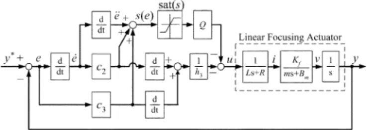
Fig. 4. Block diagram of OFSMC method for focusing.
The control input of the OFSMC in an approaching mode can be designed as
(18) where the switch function is defined as
if if if
(19) and is a constant that represents the maximum boundary of system states and disturbance. Since the control law given in (18) is discontinuous across the sliding surface, it gives rise to chattering in trajectory tracking. The chattering problem can be remedied by smoothing out the discontinuity within a thin boundary layer neighboring the sliding surface [5]. Hence, a saturation function is adopted to replace the ; i.e., (20) Therefore, the controller in (18) can be rewritten as
(21) The closed-loop block diagram of the OFSMC method for a focusing control system in a DVC is shown in Fig. 4. In order to minimize the control error, the design parameter in (21) can be adjusted based on an energy function expressed by
(22) V. EXPERIMENTALRESULTS
The hardware block diagram of the focusing control system in the LFA is depicted in Fig. 5. The suitable control algorithm written in C/C++ language is constructed in a microprocessor to obtain fast dynamic focusing characteristics. Two-channel analog/digital converters (ADC) are contained in the micropro-cessor to acquire signals of the position encoder. Two sinusoidal signals with 90 phase shift are generated from the position en-coder and then pass through the active low-pass filters and in-strumentation amplifiers before entering the two-channel ADC. Next, the PEA uses position encoder signals to determine ac-curate position of the movable part in the LFA. Additionally, the PID and OFSMC algorithms based on the PEA are written in the microprocessor for DVCs’ focusing. The transient and steady-state responses are shown in Fig. 6. An LFA for focusing operation in a DVC is manufactured with low power consump-tion. The proposed OFSMC method based on the PEA performs better and faster than PID control. The focusing response and steady-state error by using the OFSMC method are 60-ms set-ting time and 7 m, respectively, which are only half and
one-Fig. 5. Hardware block diagram for focusing.
Fig. 6. Step responses by using (a) PID and (b) OFSMC methods for focusing.
third of those in PID control when the movable part of the LFA moves 5 mm stroke, and the performance satisfies the image re-quirement of optics. Therefore, the focusing control system with OFSMC method can obtain better performance than the PID controller despite vibration and disturbance. Clear CCD images can be obtained immediately during focusing in DVCs.
VI. CONCLUSION
This paper develops the OFSMC method based on the PEA for focusing control to achieve faster focusing response despite vibration and friction of the movable parts of an LFA in a DVC. The PEA has been developed to calculate the position of the movable part in an LFA. The performance by using the OFSMC method is better than employing PID control. As a consequence, clear CCD images can be obtained immediately during focusing in DVCs.
ACKNOWLEDGMENT
This work was supported by the Electronics and Opto-elec-tronics Research Laboratories, Industrial Technology Research Institute. This paper was presented at the Tenth Joint Mag-netism and Magnetic Materials–International Magnetics (MMM–INTERMAG) Conference. See IEEE TRANSACTIONS ONMAGNETICS, vol. 43, no. 6, June 2007.
REFERENCES
[1] H. C. Yu, T. Y. Lee, S. J. Wang, M. L. Lai, J. J. Ju, D. R. Huang, and S. K. Lin, “Design of a voice coil motor used in the focusing system of a digital video camera,” IEEE Trans. Magn., vol. 41, no. 10, pp. 3979–3981, Oct. 2005.
[2] H. C. Yu, L. T. Kuo, S. J. Wang, J. J. Ju, and D. R. Huang, “The servo control of an auto-focus linear actuator in an auto-focus video camera,” in Proc. Taiwan-Korea Data Storage Symp., Taiwan, R.O.C., Oct. 2005. [3] G. F. Franklin, J. D. Powell, and A. Emami-Naeini, Feedback Control
of Dynamic Systems, 3rd ed. New York: Addison-Wesley, 1994. [4] V. I. Utkin, Sliding Modes in Control Optimization. New York:
Springer-Verlag, 1993.
[5] J. J. E. Slotine and J. A. Coetsee, “Adaptive sliding controller synthesis for non-linear systems,” Int. J. Contr., vol. 43, no. 6, pp. 1631–1651, 1986.
Manuscript received February 6, 2007. Corresponding author: H.-C. Yu (e-mail: hsingchengyu@itri.org.tw).