L-band Erbium-doped fiber laser with
coupling-ratio controlled wavelength tunability
Gong-Ru Lin*
Graduate Institute of Electro-Optical Engineering and Department of Electrical Engineering National Taiwan University
No. 1, Roosevelt Rd. Sec. 4, Taipei 106, Taiwan R.O.C. *grlin@ntu.edu.tw
Jun-Yuan Chang and Yu-Sheng Liao
Department of Photonics & Institute of Electro-Optical Engineering, National Chiao Tung University 1001 Ta Hsueh Rd., Hsinchu 300, Taiwan R.O.C.
Hai-Han Lu
Department of Electro-Optical Engineering, National Taipei University of Technology 1, Sect. 3 Chung-Hsiao E Rd., Taipei 104, Taiwan R.O.C.
Abstract: By controlling the output coupling ratio, we demonstrate a
novel wavelength-tunable L-band Erbium-doped fiber laser (EDFL) with a maximum tuning range up to 58 nm (from 1567 to 1625 nm) by controlling its output coupling ratio between 1% and 99%. The L-band EDFL is configured by using a bi-directionally dual-wavelength pumped EDFA in close-loop with an output coupler of tunable coupling ratio and an air-gap inserted FC/PC connector pair. Such an EDFL exhibits a quantum efficiency of 42% and an ultra-high power conversion efficiency of 37% under optimized pumping scheme, providing the small-signal gain and output power of ~34 dB and 91 mW, respectively. Low variation of <1.2 dB on channel power, power fluctuation of 0.04% and a narrow linewidth of 0.03 nm are obtained.
©2006 Optical Society of America
OCIS codes: (140.3500) Lasers, erbium; (140.3600) Lasers, tunable.
References and links
1. Y. Sun, J. W. Shlhoff, A. K. Srivastava, J. L. Zyskind, T. A. Strasser, J. R. Pedrazzani, C. Wolf, J. Zhou, J. B.Judkins, R. P. Espindola, and A. M. Vengasarkar, “80nm ultra-wideband erbium-doped silica fibre amplifier,” Electron. Lett. 33, 1965-1967 (1997).
2. S. M. Zhang, Y. F. Lu, X. F. Yang, F. J. Dong, H. J. Wang, and X. Dong, “Wavelength tunable linear cavity cladding pump Er3+/Yb3+ co-doped fiber laser operating in L-band,” Opt. Quantum Electron. 37, 417-424 (2005).
3. T. A. Haddud, M. H. Al-Mansoori, A. K. Zamzuri, S. Shaharudin, M. K. Abdullah, and M. A. Mahdi, “24-Line of Brillouin-Erbium Fiber Laser Utilizng Fabry-Perot Cavity in L-band,” Microwave Opt. Technol. Lett. 45, 165-167 (2005).
4. S. W. Harun and H. Ahmad, “Multiwavelength Laser Comb in L-band Region with Dual-Cavity Brillouin/Erbium Fiber Laser,” Jpn. J. Appl. Phy. 41, L1234-L1236 (2002).
5. Q. H. Mao, and W. Y. Lit, “Optical Bistability in an L-Band Dual-Wavelength Erbium-Doped Fiber Laser with Overlapping cavities,” IEEE Photon. Technol. Lett. 14, 1252-1254 (2002).
6. H. Chen, M. Leblanc, and G. W. Schinn, “Gain enhanced L-band optical fiber amplifiers and tunable fiber lasers with erbium-doped fibers,” Opt. Commun. 216, 119-125 (2003).
7. Q. H. Mao and W. Y. Lit, “Widely tunable L-band erbium-doped fiber laser with fiber Bragg gratings based on optical bistability,” App. Phys. Lett. 82, 1335-1337 (2003).
8. X. H. Feng, Y. G. Liu, S. H. Yuan, G. Y. Kai, W. G. Zhang, and X. Y. Dong, “L-Band switchable dual-wavelength erbium-doped fiber laser based on a multimode fiber Bragg grating,” Opt. Express 12, 3834-3839 (2004).
9. M. Melo, O. Frazao, A. L. J. Teixeira, L. A. Gomes, J. R. Ferreira da rocha, and H. M. Salgado, “Tunable L-band erbium-doped fibre ring laser by means of induced cavity loss using a fibre taper,” Appl. Phys. B 77, 139-142 (2003).
10. J. Lee, U. C. Ryu, S. J. Ahn, and N. Park, “Enhancement of Power Conversion Efficency for an L-band EDFA with a Secondary Pumping Effect in the Unpumped EDF Section,” IEEE Photon. Technol. Lett. 11, 42-44 (1999). 11. X. Y. Dong, P. Shum, N. Q. Ngo, H. Y. Tam, and X. Y. Dong, “Output Power Characteristics of Tunable
Erbium-Doped Fiber Ring Lasers,” J. Lightwave Technol. 23, 1334-1341 (2005).
12. S. Q. Yang, C. L. Zhao, H. Y. Meng, L. Ding, X. O. Dong, S. H. Yuan, G. Y. Kai, and Q. D. Zhao, “Wavelength tunable erbium-doped fiber ring laser operating in L-band,” Opt. and Quantum Electron. 35, 69-73 (2003). 13. P. Franco, M. Midrio, A. Tozzato, M. Romagnoli, and F. Fontana, “Characterization and optimization criteria for
filterless erbium-doped fiber lasers,” J. Opt. Soc. Am. B 11, 1090-1097 (1994).
14. H. Suzuki, M. Fujiwara, N. Takachio, K. Iwatsuki, T. Kitoh, and T. Shibata, “12.5-GHz spaced 1.28-Tb/s (512-channel_2.5 Gb/s) super-dense WDM transmission over 320-km SMF using multiwavelength generation technique,” IEEE Photon. Technol. Lett. 14, 405-407 (2002).
15. T. Pfeiffer, H. Schmuck, and H. Bülow, “Output power characteristics of erbium-doped fiber ring laser,” IEEE Photon. Technol. Lett. 4, 847-849 (1992).
16. M. Mignon and E. Desurvire, “An analytical model for the determination of optimal output reflectivity and fiber length in erbium-doped fiber lasers,” IEEE Photon. Technol. Lett. 4, 850-852 (1992).
17. J. L. Wagener, P. F. Wysocki, M. J. F. Digonnet, and H. J. Shaw, “Effects of concentration and clusters in erbium-doped fiber lasers,” Opt. Lett. 18, 2014-2016 (1993).
18. X. Dong, N. Q. Ngo, P. Shum, B.-O. Guan, H.-Y. Tam, and X. Dong, “Concentration-induced nonuniform power in tunable erbium-doped fiber lasers,” Opt. Lett. 29, 358-360 (2004).
19. X. Dong, P. Shum, N. Q. Ngo, C. C. Chan, B.-O. Guan, and H.-Y. Tam, “Effects of active fiber length on tunability of erbium-doped fiber ring lasers,” Opt. Express 11, 3622-3627 (2003).
20. T. Georges and E. Delevaque, “Analytical modeling of high-gain erbium-doped fiber amplifiers,” Opt. Lett. 17, 1113-1115 (1992).
21. X. Dong, P. Shum, N. Q. Ngo, H. Y. Tam, and X. Dong, “Output Power Characteristics of Tunable Erbium-Doped Fiber Ring Lasers,” J. Lightwave Technol. 23, 1334-1341 (2005)
22. H. Ono, M. Yamada, T. Kanamori, S. Sudo, and Y. Ohishi, “1.58-μm Band Gain-Flattened Erbium-Doped Fiber Amplifier for WDM Transmission Systems,” J. Lightwave Technol. 17, 490-496 (1999).
23. C. C. Renaud, R. J. Selvas-Aguilar, J. Nilsson, P. W. Turner, and A. B. Grudinin, “Compact High –Energy Q-Switched Cladding-Pumped Fiber Laser with a Tuning Range Over 40 nm,” IEEE Photon. Technol. Lett. 11, 976-978 (1999).
24. S. Yamashita, and M. Nishihara, “Widely Tunable Erbium-Doped Fiber Ring Laser Covering Both C-band and L-band,” IEEE J. Sel. Top. Quantum Electron. 7, 41-43 (2001).
1. Introduction
Owing to the insufficient channel capacity of the dense-wavelength-division-multiplexed (DWDM) systems at C-band, the long-wavelength band (L-band) Erbium-doped fiber
amplifier (EDFA) covering a wavelength range from 1570 nm to 1610 nm1 have been
comprehensively investigated to enlarge the transmission capacity. Versatile economic and efficient schemes of the wavelength-tunable Erbium-doped fiber lasers (EDFLs) operated at L-band have also emerged to meet the demand on testing L-band fiber-optic devices. Typically, the gain media such as the dense erbium-doped fiber, the erbium-ytterbium co-doped double clad fiber2, and the brillouin-erbium fiber3, etc., were employed to configure the L-band EDFLs in dual resonant cavity4, linear overlapping cavity5, and single ring cavity6. Different approaches for wavelength-tuning the EDFL with the intra-cavity Fabry–Perot filters7 and the fiber Bragg gratings (FBGs)8 were proposed. In particular, the wavelength-tunability of L-band EDFL via a cavity-loss control was demonstrated by opto-machanically bending the single-mode fiber in the EDFL cavity9. In this work, we present a coupling-ratio controlled scheme to demonstrate a full L-band EDFL with a wavelength-tuning range over 45 nm and a low variation on the output powers of different channels. By using a highly doped EDF with an optimized length, the ultra-high quantum efficiency and power-conversion rate of the EDFL can be approached under optimized bi-directional pumping scheme, which shows an improvement on conversion efficiency of more than 10% than those reported using conventional L-band EDFA configurations10.
2. Experimental setup
The experimental setup of the coupling-ratio controlled wavelength-tunable EDFL is shown in Fig. 1. It consists of an L-band EDFA with a bi-directionally 980nm/1480nm pumping scheme. The specific EDF (Fibercore L-band fiber, DF1500L) exhibits a large absorption of 17.5 dB/m at 1531nm. Under an optimized operation, both a forward pumping of 17.5 mW at 980 nm and a backward pumping of 200 mW at 1480 nm are employed.
Fig. 1. A coupling-ratio controlled wavelength tunable L-band EDFL with a tunable-ratio optical coupler (TROC).
This EDFA further takes the advantage on using a reduced length of the specially
designed L-band fiber with high Erbium (Er3+) concentration, which offers an ultra-wide
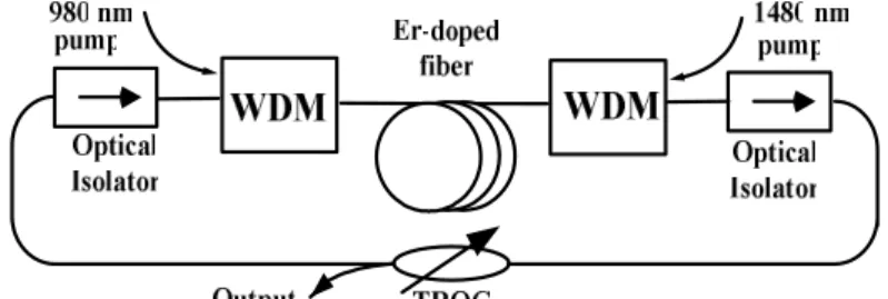
amplified spontaneous emission spectrum ranged between 1538 nm and 1628 nm (see Fig. 2) with a comparable gain and a suppressed noise power. Versatile pumping schemes have been investigated to construct a low-noise and high-gain L-band EDFA as the gain medium. The forward 980nm and backward 1480nm cascaded pumping geometry is selected for pumping the 45m-long EDF via the 980nm/1550nm and 1480nm/1550nm WDM couplers, respectively, in which the forward pumping at 980nm is effective for improving the noise characteristics, and the backward pumping at 1480nm benefits from a better quantum conversion efficiency
and gain coefficient11, 12. With such a simplified EDFA, an extremely high power conversion
efficiency (PCE) of 37% associated with a small-signal gain of 34.8 dB and a wavelength dependent gain deviation of 6 dB is achieved.
Table.1 PCE and Gain of the EDFA constructed with different Forward/Backward pumping schemes. Pumping Wavelength Power (mW) Length (m) PCR (%) Gain (dB)
980/1480 215 15 24.7 30.9 1480/1480 215 15 21.2 35.7 980/1480 215 30 36.6 33.5 1480/1480 239 30 33.1 37.2 980/1480 270 45 30.6 31.1 1480/1480 225 45 37 34.8 980/1480 230 60 20 35.2 1480/1480 400 60 23.6 38.5
To configure the EDFL, two optical isolators are used to ensure the unidirectional propagation of the light, preventing the spatial hole burning effect in the EDFA from bi-directional operation and allowing a stable single-frequency operation simultaneously. In particular, a 1×2 tunable-ratio optical coupler (TROC) is inserted into the EDFL ring-cavity, in which the coupling ratio can be detuned from 0.5% to 99.5%. The maximum output power is obtained at an output ratio of 90%, whereas the longest output wavelength has to be achieved at a coupling ratio of 10 %.
3. Operating Principle
To discuss the wavelength tuning mechanism in more detail, we have referred to a modeling
work published by Franco et al.13, in which the wavelength tuning mechanism is deducted by
considering the rate equations of a three-level system employed for the EDFL with an EDF length of L. ), ( ) ( 1P z n A dz z dP p p p p ρ σ − = ), ( ] ) ( ) ( [ ) ( 1 2 n P z n A dz z dP s A E s s = ρσ λ −σ λ , 1 } ) ( ] ) ( ) ( [ ) ( { 1 2 1 1 2 n P z P n n P z P n n sat s s E A sat p p − = − − = λ σ λ σ
Where Pp sat=[hνpA]/[σpτAp], Ps sat=[hνsA]/[σsτAs], Pp(z) is the pumping power, Ps(z) is the
forward signal power, σp is the pumping absorption cross-section, σE(λ) and σA(λ) are the
emission and the absorption cross sections, ρ is the doping concentration, Ap and As are the
integrals of the pump and the signal, nl and n2 are the lower and the upper laser level
population fractions, τ is the upper laser level lifetime, and A is the core area of the EDF. The EDFL cavity loss of ΓΤΟΤ≡P1/P3=γΓ is mainly attributed to the output coupler loss (γ) and the
intrinsic cavity loss (Γ). By extracting the EDFL power from the output coupler of a fraction T, the output power of the EDFL can be described as Pout=TP1 with 0<T<1, and the output
coupling and intrinsic cavity losses is defined as γ≡P1/P2=1/(1-T) with γ>1 and Γ≡P2/P3 with
Γ>1, respectively. The gain of EDFL satisfies the conditions of G(λ0)=ΓTOT(λ0) and G(λ≠ λ0)
<ΓTOT(λ), where λ0 is the emission wavelength. In the case, the gain of the EDFL is given by
]} ) 0 ( ) ( ln[ ) ( ) ( ) ( exp{ } ] ) ( ) ( [ exp{ ) , ( 0 2 1 p p p A L E s P L P g L g dz n n A L G α λ α λ λ λ σ λ σ ρ λ =
∫
− = + + ,where g(λ)=σEAsρ, α(λ)=σA(λ)Asρ, and αp= σpApρ denote the gain, the attenuation, and the pumping absorption coefficients, respectively. Therefore, the EDFL operated at a certain wavelength of λ must satisfy the following relation:
. 0 )]} ( ln[ ] ) 0 ( ) ( ln[ ) ( ) ( ) ( { max + + − Γ λ = α α λ λ λ λ TOT p p p P L P g L g
A correlation between the cavity loss and the lasing wavelength can equivalently be expressed as a function of λ by ( ) ( ) ln[ ( )] ln[ ] ( ) (0) ( ) ( ) p TOT p p p P L g L P g λ λ α α λ λ α λ − Γ = − ≡ − Ψ +
The above equation obtained from previous work13 thus determines the emission
wavelength of the EDFL under a specific loss parameter. The net gain profile of the EDFL results from the linear superposition of the emission and the absorption curves, in which the corresponding coefficients are added and determined by different population inversion conditions occurred in the laser cavity. Since the emission and the absorption curves of the EDFL differ from each other in both the shape and the spectral position, the gain-maximum wavelength could also be detuned as the cavity loss or coupling ratio of the EDFL changes. That is, a corresponding variation of the gain-maximum position as well as the lasing wavelength of the EDFL can be determined as the cold-cavity loss of EDFL changes.
4. Results and discussion
The amplified spontaneous emission of the EDFA has revealed a wide spectral response covering the C- and L-bands, as shown in Fig. 2. In principle, the wavelength tunablility of an EDFL can be greatly affected by several cavity parameters such as the intra-cavity loss, the
output coupling ratio (or reflectivity), and the active fiber length14-19. A deeply saturated EDFA under high-power feedback injection has shown the capability to offer wide-band and flat gain20, and the L-band EDFL can be readily available by minimizing the intra-cavity loss to keep largest gain in the EDFL cavity. The total intra-cavity loss has previously been understood as the most important factor that affects both the output power and the wavelength
tuning range21. The tuning bandwidth increases significantly as the intra-cavity loss is
reduced, whereas the output power of the EDFL shows an opposite trend. That is, the wavelength tuning range can be broadened by reducing the output coupling ratio. Previously, a numerical modeling for the C+L-band EDFL at different intra-cavity losses also supports
this statement11, the numerical results on the wavelength dependent output power for an EDFL
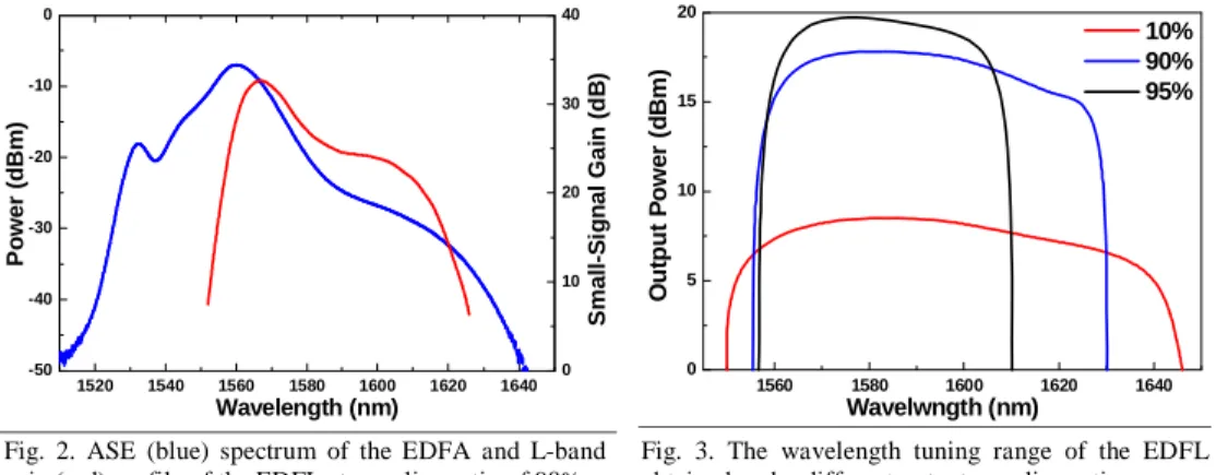
at different intra-cavity losses has confirmed that the reducing cavity loss can effectively extend the wavelength tuning rage of the EDFL. In our case, the output-coupling-ratio or cavity-loss dependent wavelength tuning rage of the EDFL has also been determined with a bandpass filter, the EDFL is found to exhibit an ultra-wide wavelength tuning range of nearly 60 nm under a 10% cavity-loss condition (see Fig. 3). Large bandwidth covering C- and L-bands can be obtained under a very low intra-cavity loss, while for high intra-cavity loss only a narrow bandwidth in C-band is obtained. Both the laser output power and the tunable range are very sensitive to the intra-cavity loss. The wavelength tuning range significantly increases, whereas the output power of the EDFL enlarges as the intra-cavity loss is reduced.
1520 1540 1560 1580 1600 1620 1640 -50 -40 -30 -20 -10 0 0 10 20 30 40 Po w e r ( d B m ) Wavelength (nm) S m all-S ig n a l Ga in ( d B ) 1560 1580 1600 1620 1640 0 5 10 15 20 10% 90% 95% O u tput P o we r (d B m ) Wavelwngth (nm)
Fig. 2. ASE (blue) spectrum of the EDFA and L-band gain (red) profile of the EDFL at coupling ratio of 90%.
Fig. 3. The wavelength tuning range of the EDFL obtained under different output coupling rations.
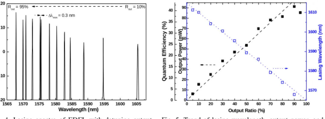
Figure 4 illustrates the lasing spectra of the EDFL covering a tuning range of 45 nm at output coupling ratios ranging between 5% and 90%. The maximum tuning range can extend to 58 nm by minimize output coupling ratio to <1%, which corroborates well with theoretical prediction in previous works. As the cavity-loss increases, the maximum output power and
the wavelength tuning range are concurrently reduced22. By using the TROC based coupling
ratio detuning technique, our experimental results not only correlate well with the theoretical
observation21, but also demonstrate the coupling-ratio dependent peak EDFL wavelength
shifting phenomenon. These results sophisticate the operation of a widely tunable L-band EDFL. The detuning of intra-cavity loss may achieve an extremely large tuning range at a scarification on output power of the EDFL, as shown in Fig. 4. Nonetheless, the accurate and repeatable wavelength selection can easily be achieved with a precise control on the output coupling ratio. In experiment, a minimum wavelength tuning resolution of 0.3 nm can be obtained under a change in coupling ratio of 0.6%, corresponding to tuning slope of 0.5 nm/%. Figure 5 shows the output laser wavelength, power, and corresponding quantum efficiency as a function of the output coupling ratio detuned using TROC. As a result, the maximum output power of the EDFL is monotonically decreasing from 91 to 7 mW as its wavelength is linearly tuned from 1567 to 1612 nm under a variation of output coupling ratio from 95% to 5 %. A maximum quantum efficiency of up to 42% is obtained at an output coupling ratio of 90%.
1565 1570 1575 1580 1585 1590 1595 1600 1605 -20 -10 0 10 20 Po w e r ( d B m ) Wavelength (nm) Rout = 10% Rout = 95% Δλmin= 0.3 nm 0 5 10 15 20 25 30 35 40 0 10 20 30 40 50 60 70 80 90 100 0 10 20 30 40 50 60 70 80 90 Output Ratio (%) Out put P o we r ( m W) 1570 1580 1590 1600 1610 La s in g Wa v e le ngt h (n m ) Q u an tu m E ff ic ien cy ( % )
Fig. 4. Lasing spectra of EDFL with detuning output coupling ratio.
Fig. 5. Trend of lasing wavelength, output power, and quantum efficiency with output coupling ratio.
Under a low-output and wide-band tunable condition with coupling ratio of only 10 %, the corresponding quantum efficiency of 8% is still comparable with previous results11, 12. At a constant output coupling ratio of 90%, it is found that each filtered output channel exhibits the power of greater than 18.4 dBm and the maximum of 19.6 dBm in observed under the pumping power of 217.5 mW, as shown in Fig. 6. Such a deviation of 1.2 dB is already
smaller than the best value of 1.5 dB reported in previous work9. Nonetheless, it is
unavailable to obtain a tunable-filtered EDFL with such a broadband wavelength range as compared to the coupling loss controlled EDFL with its maximum lasing wavelength up to 1625 nm. Moreover, a highly stable output with power variation of 0.036mW (0.04%) over 10 min is obtained. The tuning range and resolution of lasing wavelength was mainly determined by the gain profile of the EDF since the dynamic range on the coupling ratio of the TROC is nearly 100% in our case. The EDFL is unable to operate in the C-band with insufficient gain as the design of the specific EDF which benefits from a better transition of the power from C-band to L-C-band. In comparison, similar phenomenon has previously been observed using a
fiber bending architecture proposed by Melo et al.9, in which the taper-bending curvature of
the intra-cavity single-mode fiber (SMF) is adjusted to provide wavelength tunability. The smaller output coupling ratio not only makes the wavelength tuning range broader, but also favors the EDFL lasing at a longer wavelength. The increased bending radius of the SMF introduces additional cavity loss in the EDFL ring cavity, thus enabling a blue-shifted EDFL wavelength. However, the induced loss can only be determined as a function of a the position of the micrometer drive, and the corresponding EDFL wavelength can not be accurately controlled due to the difficulty of experimentally determining the exact curvature radius applied to the SMF taper.
1560 1570 1580 1590 1600 1610 1620 1630 1640 10 15 20 0 5 10 15 20 B a n d p ass F ilt er ed E D F L P o w e r ( d B m ) Wavelength (nm) L o s s C o ntr o lle d E D FL P o w e r (dB m ) 1605.3 1605.4 1605.5 1605.6 1605.7 0.0 0.2 0.4 0.6 0.8 1.0 free-running with bandpass filter with air-gap etalon
Pow e r (. a .u. ) Wavelength (nm) Δλ = 0.03 nm
Fig. 6. Wavelength dependent output power of a coupling loss controlled EDFL (solid square) a tunable filter controlled EDFL (hollow circle) at output coupling ratio of 90%.
Fig. 7. The lasing linewidth without (dotted line) or with (solid square) an air-gap inserting between FC/PC fiber connectors. The bandpass filtered EDFL spectrum (dashed line) is also show for comparison.
In addition, the dielectric, grating, and fiber Fabry-Perot (FFP) filters were extensively
employed to implement widely tunable EDFLs covering C+L band (1520-1600 nm)23. The
dielectric filter is frequently used with a tunable range limited to 40 nm, which is recently replaced by the grating filter tunable over 100 nm. Nonetheless, the grating usually exhibits a large polarization dependency and a large splicing loss of >5 dB during fiber coupling. The FFP filter is an all-fiber based device having a most wide tuning range of >100 nm, a relatively low loss of <2 dB and an extremely low polarization dependence of 0.1 dB24. It is preferable to have an all-fiber based architecture since which exhibits the advantages such as robust, easily connectable, and potentially cost-effective. The innovation of the proposed L-band EDFL system is to introduce a tiny air-gap between the FC/PC connectors of the fiber patch cord prior to the output coupler of the EDFL. This is done by first mounting the FC/PC connector at a precisely aligned holder and then separating the FC/PC connector each other by using one-dimensional translation stage. The home-made air-gap adjuster functions as not only an intra-cavity Fabry-Perot filter but also a cavity loss controller in the L-band EDFL system. Note that the lasing linewidth of the EDFL output can be further narrowing from 0.3 nm to 0.03 nm (see Fig. 7) by simply inserting such a tiny air-gap between the FC/PC connectors of fiber patch cord. In principle, the wavelength tuning of the L-band EDFL through loss modulation is well known and it generally results in step tuning rather than the continuous tuning reported by our work. Presumably, our approach is based on the convolution of the spectral responses in the tunable coupler and a weak fiber-based air-gap etalon, which releases any kinks in the gain tilt function of the EDFL. The air-gap based etalon thus becomes an interesting innovation when combining with the loss modulation technique, as it concurrently results in single-frequency and wavelength tuning operation of the L-band EDFL.
5. Conclusions
We have demonstrated an output-coupling-ratio controlled, full long-wavelength-band erbium-doped fiber ring laser by using a bi-directionally dual-wavelength pumped EDFA in close-loop with an output coupler of tunable coupling ratio. The L-band EDFL is wavelength-tunable from 1567 nm to 1612 nm at a maximum quantum efficiency of 42%, respectively with ultra-high power conversion efficiency of 37%, comparable gain of 34 dB, and maximum output power of up to 91mW. The minimum wavelength tuning resolution of 0.3 nm is achieved under the maximum wavelength tuning range of up to 45 nm covering whole L-band, while a low channel power variation of <1.2dB and a stable output with 0.04% power fluctuation is reported.
Acknowledgments
The authors thank the National Science Council of Republic of China for financially supporting this research under grants NSC 94-2215-E-002-040 and NSC95-2221-E-002-448.