Fuzzy control design of a magnetically actuated optical image stabilizer with hysteresis
compensation
Tse-Yi Tu, Paul C.-P. Chao, Chi-Wei Chiu, Chun-Chieh Wang, and Jeng-Shen Huang
Citation: Journal of Applied Physics 105, 07F124 (2009); doi: 10.1063/1.3068542
View online: http://dx.doi.org/10.1063/1.3068542
View Table of Contents: http://scitation.aip.org/content/aip/journal/jap/105/7?ver=pdfcov Published by the AIP Publishing
Articles you may be interested in
Measurement method for determining the magnetic hysteresis effects of reluctance actuators by evaluation of the force and flux variation
Rev. Sci. Instrum. 84, 075003 (2013); 10.1063/1.4813278
Design and optimization of voice coil actuator for six degree of freedom active vibration isolation system using Halbach magnet array
Rev. Sci. Instrum. 83, 105117 (2012); 10.1063/1.4764002
Hybrid TakagiSugeno Fuzzy FED PID Control of Nonlinear Systems AIP Conf. Proc. 1019, 99 (2008); 10.1063/1.2953061
Optimal design and experimental verification of a magnetically actuated optical image stabilization system for cameras in mobile phones
J. Appl. Phys. 103, 07F136 (2008); 10.1063/1.2839782
Adaptive direct metal/material deposition process using a fuzzy logic-based controller J. Laser Appl. 17, 200 (2005); 10.2351/1.2098811
[This article is copyrighted as indicated in the article. Reuse of AIP content is subject to the terms at: http://scitation.aip.org/termsconditions. Downloaded to ] IP: 140.113.38.11 On: Wed, 30 Apr 2014 15:24:15
Fuzzy control design of a magnetically actuated optical image stabilizer
with hysteresis compensation
Tse-Yi Tu,1 Paul C.-P. Chao,1,a兲 Chi-Wei Chiu,1 Chun-Chieh Wang,2 and Jeng-Shen Huang3
1
Department of Electrical and Control Engineering, National Chiao Tung University, Hsinchu 300, Taiwan
2Mechanical and Systems Research Laboratories, Industrial Technology Research Institute, Hsinchu
300, Taiwan
3Department of Mechanical Engineering, Chung Yuan Christian University, Chungli 320, Taiwan
共Presented 14 November 2008; received 2 October 2008; accepted 6 November 2008; published online 6 April 2009兲
A fuzzy controller共FC兲 is designed for a magnetically actuated optical image stabilizer 共OIS兲 in order to suppress the vibrations caused by hand shakings and hysteresis. To this end, the dynamic model of the OIS with consideration of hysteresis is first established, along with assuming the hand-shaking vibration as sinusoidal excitations. It is clearly shown that with capability of continuing parameter tuning, the FC is superior to the conventional PID for vibration suppression. © 2009 American Institute of Physics.
关DOI:10.1063/1.3068542兴 I. INTRODUCTION
An optical image stabilization 共OIS兲 system is widely implemented into the digital still cameras for mobile devices1–3 in order to improve blurred images. Previous works4,5were devoted to downsize the OIS system using the optimization method, genetic algorithm共GA兲, while keeping sufficient magnetic actuation force. This leads to nonunifor-mity resided in magnetic flux density and actuation and a hysteresis relation between the applied voltage to OIS and actuated motions. The OIS inevitably exhibit an hysteretic phenomena while actuated to compensate the external har-moniclike vibration.
A dynamic model considering hysteresis effect to predict the displacement of the lens is first established via Preisach model.6 A fuzzy controller7,8 共FC兲 is next designed to per-form precision positioning of the OIS with a feedforward compensation loop to compensate the identified hysteresis and a feedback loop to overcome shaking vibrations. It can be clearly shown based on simulations that with capability of continuing parameter tuning, the FC is superior to the con-ventional PID for vibration suppression.
II. SYSTEM MODELING
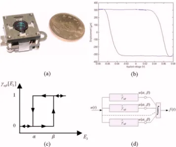
The mechanism of the OIS system is mainly composed of horizontal and vertical positioning platforms carrying im-age sensor; permanent magnets, yokes, and VCMs for actua-tion. Figure1共a兲shows the photography of the proposed OIS system. Experiment is conducted first to investigate the ac-tuation performance of the OIS system. It is found that the hysteresis phenomenon, as shown in Fig. 1共b兲, is mainly caused by nonuniformity of magnetic field distribution and magnetic hysteresis.
A. Preisach model for hysteresis
The Preisach model,6is adopted herein to prescribe the force term f共t兲, which analogies the hysteresis behavior to a force term. The force term f共t兲 can be expressed as a func-tion of the corresponding applied electric field E by the in-tegral,
f共t兲 =
冕冕
␣ⱖ共␣,兲␥␣关E共t兲兴d␣d, 共1兲
where␥␣ is the elementary operator as shown in Fig.1共c兲, which is also a function depending on the electric field E, a function of applied voltage in OIS. ␥␣ varies from 0 to 1, emulating an on-off to distinguish the change in input E either in ascending or descending for reflecting the hysteresis effect. Also seen from Fig.1共d兲 is that共␣,兲 is a function
a兲Author to whom correspondence should be addressed. Electronic mail:
FIG. 1.共Color online兲 共a兲 Photograph of the proposed OIS. 共b兲 Experimen-tal displacement hysteresis.共c兲 Preisach model of hysteresis. 共d兲 Elementary hysteresis operator.
JOURNAL OF APPLIED PHYSICS 105, 07F124共2009兲
0021-8979/2009/105共7兲/07F124/3/$25.00 105, 07F124-1 © 2009 American Institute of Physics
[This article is copyrighted as indicated in the article. Reuse of AIP content is subject to the terms at: http://scitation.aip.org/termsconditions. Downloaded to ] IP: 140.113.38.11 On: Wed, 30 Apr 2014 15:24:15
of␣and, so-called the Preisach function, which captures a variety of different hysteresis characteristics with given val-ues of␣and.共␣,兲 is in fact the corresponding switch-ing values of E between ascendswitch-ing and descendswitch-ing pro-cesses.
B. Magnetic force
The magnetic force is considered as an external force and will be interacted with the hysteresis force term. The electromagnetic force Fecould be, therefore, obtained by
Fe= N⫻ i ⫻ lw⫻ Bg= N⫻
VA
L ⫻ lw⫻ Bg, 共2兲
where N is the number of coil winding, i is the applied cur-rent to the voice coil, lmis the effective length of the voice
coil, and Bgis the magnetic flux density. Furthermore, V, A,
, and L are the applied voltage, the cross-sectional area of the coil, the electric conductivity of coil, and the total length of the coil, respectively.
C. Dynamic modeling
The structure of OIS actuator in Fig.1could be consid-ered as a lumped model, where the lens/holder is integrally considered as a mass and the springs are the stiffness for suspension. Taking the aforementioned hysteresis effects and magnetic force into account, the equation of motion for the OIS actuator can be expressed by
Mq¨ + Kq = Fe− f, 共3兲
where M and K are the mass and stiffness matrices, respec-tively. Furthermore, the vector q denotes the degrees of free-dom 共DOFs兲 of the OIS actuator, which are along vertical and horizontal directions of the lens holder motion. Fe is a vector, which consists of the magnetic forces as shown in Eq.
共2兲 in two moving directions. f is the predefined hysteresis force term, which is modeled by Eq.共1兲. Hence, the equation of motion of OIS actuator in two DOFs of the OIS be for-mulated as
冋
m 0 0 m册
冋
x¨ y¨册
+冋
k1x+ k2x 0 0 k1y+ k2y册冋
x y册
=冋
Fex Fey册
−冋
fx fy册
, 共4兲where the m denotes the integral mass of the lens and its holder, k1x, k1y, and k2x, k2y represent the stiffness of the
springs that connect the moving platforms and cellphone body in the x and y directions, respectively, Fexand Feyare
the electromagnetic forces from the VCMs in the x and y directions, respectively, and the fxand fyare the hysteresis
force terms. Due to the symmetric mechanism, the dynamic behavior is considered in single axis 共DOF兲 only in this study. Therefore, an experiment through the frequency re-sponse is conducted for identifying the unknown parameters. One can obtain the stiffness of the actuator K through the known actuator mass m. In this study, the actuator mass M is 0.926 g and stiffness K is 52 588 N/m. With the two
param-eters in hands, the transfer function can be expressed by a second order lumped model,
G共s兲 = 1
0.926⫻ 10−3s2+ 52 588+ Gn共s兲, 共5兲 where Gn共s兲 denotes the system nonlinearity caused by
aforementioned hysteresis and nonuniformity embedded in magnetic actuation forces.
III. DESIGN OF FUZZY CONTROLLER
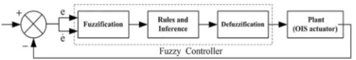
The advantages of FC method herein are using language variables to describe the characteristics of system, thus able to overcome system nonlinearities: hysteresis and nonuni-form actuation. The block diagram of applying FC to the OIS actuator is shown in Fig.2.
A. Fuzzification
Based on the results of measured variables, the control-ler could then tune the output based on the predetermined fuzzy rules. In this study, the output signal u, input error e, and its differentiation e˙ are considered as the variables. The FC system can be described with seven fuzzy values as fol-lows: NH, NM, NS, O, PS, PM, PH, and use the same Gaussian membership functions. In this study, the range for output signal u is defined from ⫺3 to 3, the range for input error e is defined from⫺0.5 to 0.5, and the range for input error differentiation e˙ is defined from ⫺1 to 1.
B. Fuzzy rule base and fuzzy inference
Since hand-shaking vibrations as sinusoidal excitations are considered in this study, the fundamental linguistic rules determine that output signal is large as input error or its differentiation is large. For the two inputs and one output in FC system for individual actuation along vertical and hori-zontal directions, the fuzzy rule base can be designed as shown in TableI, where the 14 fuzzy rules R1⬃R14for the
actuator in antishake mobile system can be fostered. FIG. 2. Block diagram of FC.
TABLE I. Fuzzy rule base of FC system.
e u e˙ u R1 NH NH R8 NH NH R2 NM NM R9 NM NM R3 NS NS R10 NS NS R4 O O R11 O O R5 PS PS R12 PS PS R6 PM PM R13 PM PM R7 PH PH R14 PH PH
07F124-2 Tu et al. J. Appl. Phys. 105, 07F124共2009兲
[This article is copyrighted as indicated in the article. Reuse of AIP content is subject to the terms at: http://scitation.aip.org/termsconditions. Downloaded to ] IP: 140.113.38.11 On: Wed, 30 Apr 2014 15:24:15
C. Defuzzification
Having forged fuzzy reasonings, linguistic output vari-ables need to be converted into numerical values. The sub-sequent defuzzification is an inverse transformation, which maps the output from the fuzzy domain back into the nu-merical domain. The center-of-area method is chosen to complete the job, which is often referred to as the center-of-gravity method because it computes the centroid of the com-posite area representing the output fuzzy variables.
IV. SIMULATION RESULTS
The hand-shake excitation is assumed harmoniclike due to the tilt angle range of ⫾2° caused by human holding hands while shooting pictures. Considering the effective fo-cal length of a commercial lens is 4.84 mm, the compensa-tion distance expected from OIS can easily be computed as 0.169 mm, which is obtained by the multiplication of focal length and tangential of tilt angle. Four kinds of periodic waves in sinusoids are considered as the desired compensa-tion movement to eliminate the hand shaking.
Four simulations results are shown in Fig.3. In Fig.3共a兲, the red curve is the simulated result using FC, which is in the frequency of 1 Hz and designates 0.08 mm for the desired displacement amplitude. The blue line is the similar results using PID control. The error between sine wave and simula-tion line was shown in Fig. 3共b兲, which are 0.0017 and 0.0046 by using FC and PID control, respectively. Figure
3共c兲shows the results with 0.15 mm for the desired displace-ment, while Fig. 3共d兲 shows the resulted errors. In terms of controller performance, the error should approach zeros to
achieve a satisfactory vibration suppression. Note that the FC owns the superiority in terms of low displacement error. The areas of peak amplitude represent those close to the two edges of the OIS mechanism, where the lowest magnetic force occurs and hysteresis effect plays a role. This shows the significantly better improvement by the designed FC over PID for overcoming the nonuniformity of magnetic force between the yoke and VCM. Figure 3共e兲–3共h兲 shows the same findings while the frequency of the desired displace-ment is increased to 2 Hz. The results also show the good expectation of magnetic hysteresis compensation. Table II
summarizes the resulted errors by FC and PID where the superiority of FC is clearly seen.
V. CONCLUSIONS
In this study, the nonlinear phenomenon of hysteresis effect and the nonuniformity of magnetic force in the VCM for OIS are improved by a newly designed FC. It is found that the FC is superior to the PID in terms of eliminating the magnetic hysteresis phenomenon.
ACKNOWLEDGMENTS
The authors are greatly indebted to the National Science Council, Taiwan for the support of the research through con-tact in Grant Nos. NSC96-2220-E-009-029.
1K. Sato, S. Ishizuka, A. Nikami, and M. Sato,IEEE Trans. Consum. Elec-tron.39, 461共1993兲.
2H. Hamano,Proc. SPIE4487, 94共2001兲.
3Z. Li, B. R. Varlow, L. A. Renforth, D. W. Auckland, and R. Shuttleworth, IEE Proc.: Electr. Power Appl.147, 431共2000兲.
4C.-W. Chiu, P. C.-P. Chao, N. Y.-Y. Kao, and F.-G. Young,J. Appl. Phys.
103, 07F136共2008兲.
5C.-W. Chiu, P. C.-P. Chao, and D.-Y. Wu,IEEE Trans. Magn.43, 2582
共2007兲.
6I. D. Mayergoyz, Mathematical Models of Hysteresis, 2,共Spinger-Verlag,
New York, 1991兲.
7M. H. Ali, T. Murata, and J. Tamura,IEEE Trans. Control Syst. Technol.
15, 144共2007兲.
8G. K. I. Mann, B. G. Hu, and R. G. Gosine, IEEE Trans. Syst. Man Cybern.29, 371共1999兲.
FIG. 3. 共Color online兲 共a兲 The simulation results with Freq.=1, Amp. = 0.08.共b兲 The error of results in 共a兲. 共c兲 The simulation results with Freq. = 1, Amp. = 0.16.共d兲 The error of results in 共c兲. 共e兲 The simulation results with Freq. = 2, Amp. = 0.08.共f兲 The error of results in 共e兲. 共g兲 The simulation results with Freq. = 2, Amp. = 0.16.共h兲 The error of results in 共g兲.
TABLE II. Simulation errors by using FC and PID.
Frequency Amplitude Error of FC Error of PID
1 0.08 0.0017 0.0046
1 0.16 0.0017 0.0092
2 0.08 0.0017 0.0046
2 0.16 0.0017 0.0091
07F124-3 Tu et al. J. Appl. Phys. 105, 07F124共2009兲
[This article is copyrighted as indicated in the article. Reuse of AIP content is subject to the terms at: http://scitation.aip.org/termsconditions. Downloaded to ] IP: 140.113.38.11 On: Wed, 30 Apr 2014 15:24:15