國
立
交
通
大
學
資訊工程學系
博
博
博
博 士
士
士
士
論
論
論
論
文
文
文
文
一個對時序工作流程管理系統進行分析的研究
A Study to Analyzing Temporal Workflow Management System
研 究 生:許懷中
指導教授:王豐堅 教授
中
中
中
中 華
華
華
華 民
民
民
民 國
國
國
國 一
一 百
一
一
百
百
百 年
年
年
年 七
七
七
七 月
月
月
月
一個對時序工作流程管理系統進行分析的研究
A Study to Analyzing Temporal Workflow Management System
研 究 生:許懷中 Student:Hwai-Jung Hsu
指導教授:王豐堅 Advisor:Feng-Jian Wang
國 立 交 通 大 學
資 訊 工 程 學 系
博 士 論 文
A DissertationSubmitted to Institute of Computer Science and Engieering College of Computer Science
National Chiao Tung University in partial Fulfillment of the Requirements
for the Degree of Doctor
in
Computer Science
July 2011
Hsinchu, Taiwan, Republic of China
一個對時序
一個對時序
一個對時序
一個對時序工作流程
工作流程
工作流程
工作流程管理系統進行
管理系統進行
管理系統進行
管理系統進行分析
分析的
分析
分析
的
的
的研究
研究
研究
研究
學生:許懷中 指導教授:王豐堅 博士
國立交通大學資訊工程學系 (研究所) 博士班
摘
摘
摘
摘
要
要
要
要
現代化企業利用工作流程管理系統統整文件、資訊系統以及人事組織以遂行其企業 目的,而針對工作流程進行分析,有助於尋找企業程序中所隱藏的問題,避免工作流程 執行時重複發生的錯誤,進而增進企業整體的效率;由於大部分具有良好行為之工作流 程皆可轉換為結構化工作流程,因此結構化工作流程模型是在進行工作流程結構健全性 分析時不可或缺的工具,此外,時序為進行工作流程正確性檢查、驗證以及工作流程效 率分析上必須考量之因素,在此博士論文中,我們將時序因素與結構化工作流程模型結 合統整而成一結構化時序工作流程模型,並且針對三種不同的領域,提出各自的分析方 法;在組織分析領域,針對使用任務與角色為基存取控制模型的工作流程管理系統,我 們建立了一個可以進行工作代理的執行框架,在此框架下,代理行為受到責任分擔以及 企業政策的制約,使用者可以手動進行工作代理授權,而系統也可以自動將緊急的工作 授權給適合的代理人;在資料分析領域,我們建立了一個從結構化時序工作流程中偵測 異常文件使用的方法,藉由這個方法對工作流程定義進行靜態分析,可以有效避免由於 異常資料操作所造成的系統意外行為;最後,針對資源領域,我們提出了一個可以在結 構化時序工作流程建構的過程中,進行資源一致性與時序條件分析的遞增性分析方法, 藉由我們的方法,工作流程設計者可以瞭解他所做的每一個設計決定對於整體工作流程 定義的影響,並且修正由於錯誤的設計邏輯所造成的潛在資源衝突。 關鍵字:工作流程、工作流程管理系統、結構化時序工作流程、代理、任務與角色為基 的存取控制模型、異常文件使用、資源衝突、遞增性分析方法
A Study to Analyzing Temporal Workflow Management System
Student: Hwai-Jung Hsu Advisor: Dr. Feng-Jian Wang
Institute of Computer Science and Engineering
National Chiao Tung University
ABSTRACT
In modern enterprises, Workflow Management System (WfMS) coordinates data, resources, and organizations to enact workflows for various business objectives. Analysis of workflows facilitates locating problems in business processes and prevents repeated errors during workflow enactment. Structured workflow model is a useful tool for analysis of structural integrity because most well-behaved workflows can be reduced to structured workflows. Besides, temporal factors are also essential for workflow analysis, especially for validation, verification and performance analysis of workflows. In this dissertation, we integrate temporal factors into structured workflow model as Temporal Structured Workflow (TS workflow) model, and develop three distinct approaches for analysis of TS workflows in various perspectives. For the organization perspective, a framework for delegating works among users in a WfMS coordinated with Task-Role-based Access Control (TRBAC) model is established. With the framework, delegations can be enacted manually or automatically under restrictions like separation of duty (SOD) and management of enterprise policies. For the data perspective, a methodology detecting artifact anomalies in TS workflows is developed. By analyzing workflow schemas with our methodology, the unexpected run-time behavior generated from abnormal data manipulation can be prevented. Finally, for the resource perspective, an incremental approach is constructed to analyze resource consistencies and temporal constraints during construction of a loop-reduced TS workflow (LRTS workflow). With our approach, designers may realize the effect of each edit operation they made on the workflow schema under design, and correct the potential resource conflicts buried in business processes immediately.
Keywords: Workflow, Workflow Management System (WfMS), Temporal Structured Workflow, Delegation, Task-Role based Access Control (TRBAC), Artifact Anomalies, Resource Conflicts, and Incremental Methodology
誌
誌
誌
誌
謝
謝
謝
謝
獻給在天上看顧著我的祖父
攻讀博士不僅僅是為了獲取一個學位,它是一場對於人生、自我以及真理的探索, 如今這漫長、無止盡的旅程將要來到轉捩點,為了直到今日所完成的小小成就,有很多 人值得感謝,首先要感謝我的指導教授王豐堅老師,感謝他在學術以及人生上對我的指 導與幫助,沒有老師的耐心與包容,我無法在這條道路上堅持到底;感謝我的博士論文 口試委員,朱治平教授、黃慶育教授、黃冠寰教授、梁德容教授、吳毅成教授以及黃世 昆教授,感謝各位口委的指導,讓本博士論文得以順利完成;感謝所有曾經直接或間接 參與過本論文相關研究的實驗室伙伴,許嘉麟、王建偉、王靜慧、張志絃、許熏任、楊 大立、簡璞、陳建志等等,感謝他們在本研究中的貢獻;感謝我的祖父,雖然他沒能親 眼看到我畢業,但是他一生努力掙來的這個家,撫育我成長茁壯;感謝我的祖母,她無 怨無悔的全力支持,讓我得以心無旁騖地進行研究;感謝我的父親,沒有他的一席話, 我不會踏上這條路,沒有他多年來的默默支持,我無以為繼;感謝我的母親,雖然她總 是說自己不懂我在作些什麼,但是她的關愛是我人生的明燈;感謝我的姑姑,感謝她為 這個家的奉獻,彌補了我因著忙碌而未足夠的孝道;感謝我的妻子,感謝她這些年在我 身後的付出以及容忍我的任性,我們還將攜手創造未來;最後,感謝所有曾經在這論文 以及我攻讀博士的過程中有所貢獻的人們,謝謝大家。目錄 – Table of Contents
摘 要 ...i
ABSTRACT ...ii
誌 謝 ...iii
目錄 – Table of Contents...iv
圖目錄 – Table of Figures ...vi
表目錄 – Table of Tables...vii
定義目錄 – Table of Definitions ...viii
演算法目錄 – Table of Algorithms ...ix
輔助定理目錄 – Table of Lemmas ...x
Chapter 1. Introduction... 1
Chapter 2. Temporal Structured Workflow Model ... 6
2.1 Basic Elements ... 6
2.2 Structured Workflow... 7
2.3 Temporal Structured Workflow ... 9
2.4 Analysis of Structural and Temporal Relationships between Processes in TS workflow... 10
2.4.1 Loop Reduction ... 10
2.4.2 Analysis of Structural Relationships between Processes in LRTS workflow . 12 2.4.3 Analysis of Twisted Temporal and Structural Relationships between Processes in LRTS workflow ... 16
Chapter 3. A Delegation Framework for WfMS based on Task-Role based Access Control and TS workflow ... 21
3.1 Background... 21
3.1.1 Task-Role based Access Control Model ... 21
3.1.2 Delegation Approaches in RBAC and TRBAC... 22
3.1.3 Separation of Duty... 24
3.2 Task and Role Model ... 24
3.3 Delegation Framework for WfMS on TRBAC ... 27
3.3.1 The properties of Delegation ... 27
3.3.2 Delegatee Decision ... 29
3.3.3 Delegation from System Request ... 32
3.3.4 Delegation from User Request ... 34
3.3.5 Revocation ... 36
3.4 Case Study ... 39
3.5 Discussion... 41
4.1 Artifact Anomalies in TS workflow... 43
4.1.1 Artifact Operations ... 43
4.1.2 Artifact Anomalies ... 45
4.2 The Methodology Detecting Artifact Anomalies in LRTS workflow ... 47
4.2.1 Gathering Structural, Temporal, Artifact Information in LRTS workflow... 47
4.2.2 Collecting Structural and Temporal Relationships between Artifact Operations in LRTS workflow ... 49
4.2.3 Detecting Blank Branch ... 57
4.2.4 Identifying Artifact Anomalies in an LRTS workflow ... 59
4.3 Case Study ... 66
4.4 Discussion... 70
4.4.1 Related Works in Analysis of Artifact Anomalies ... 70
4.4.2 Comparison between Our Approach and the Related Works ... 72
Chapter 5. Incremental Detection of Resource Conflicts in LRTS Workflow ... 74
5.1 Resource Conflicts in LRTS workflow ... 74
5.2 Edit Operations for LRTS workflow ... 75
5.3 An Incremental Algorithm Detecting Resource Conflicts in TS workflow... 80
5.3.1 Updating Estimated Active Interval for Processes after Edit Operation ... 80
5.3.2 Identifying Generation or Elimination of Resource Conflicts after Adding/Removing a Resource Reference to/from an Activity Process... 82
5.3.3 Identifying Generation or Elimination of Resource Conflicts after Alteration of EAIs... 84
5.3.4 Combining the Algorithms with Edit Operations ... 87
5.4 Case Study ... 89
5.4.1 Case 1: Adding a Resource Reference... 90
5.4.2 Case 2: Modification of the Working Duration of an Activity Process ... 90
5.4.3 Case 3: Removing an Activity Process... 91
5.5 Related Works... 92
Chapter 6. Conclusion and Future Works... 95
圖目錄 – Table of Figures
Figure 1 The Graphic Notations of the Basic Workflow Elements ... 7
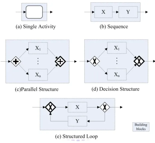
Figure 2 Building Blocks of a Structured Workflow... 8
Figure 3 A Sample Structured Workflow... 9
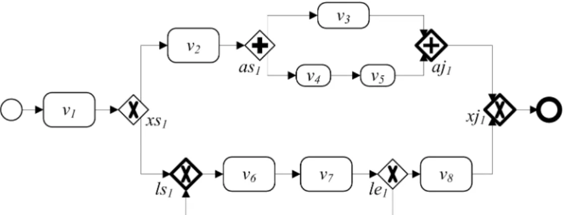
Figure 4 A Sample TS workflow ... 10
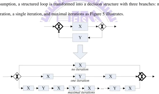
Figure 5 Refined Loop Reduction for TS Workflow Model ... 11
Figure 6 Calculation of ABStacks for Processes in an LRTS Workflow... 14
Figure 7 A Sample TS workflow with ABStacks and EAIs ... 15
Figure 8 The Temporal Relationships between Time Intervals [39] ... 16
Figure 9 Calculation of EAIs in an LRTS Workflow [34][37] ... 18
Figure 10 The TRBAC Model [17] ... 21
Figure 11 The Process for Delegation from User Request ... 35
Figure 12 (a) The Sample TS Workflow Specification, (b) The Sample Role Hierarchy and User Assignment, and (c) The Information about Tasks, Mutually-exclusive Tasks, and Authorization Applications ... 39
Figure 13 The Artifact State Transit Diagram ... 45
Figure 14 Examples for Nestedly Organized Decision and Parallel Structures ... 54
Figure 15 An Example of a Blank Branch... 58
Figure 16 The Sample TS Workflow for the Case Study in Chapter 4... 66
Figure 17 The Sample LRTS Workflow Derived from Figure 16 with Decoration of EAIs and ABStacks... 67
Figure 18 The Sample LRTS Workflow for the Case Study in Chapter 5... 89
Figure 19 The Sample LRTS Workflow after Adding a New Resource Reference ... 90
Figure 20 The Sample LRTS Workflow after Modification of a Working Duration... 91
表目錄 – Table of Tables
Table 1 Classes of Tasks in TRBAC Model [17]... 22
Table 2 Comparison of Characteristics of Various Delegation Models... 41
Table 3 Artifact Operation List for a, and the Corresponding Concurrent Operations ... 67
Table 4 The Output State of the Operations before op9 is Calculated ... 68
定義目錄 – Table of Definitions
Definition 1 (Workflow Model)... 7
Definition 2 (Path) ... 7
Definition 3 (Structural Relationships in a Structured Workflow) ... 9
Definition 4 (TS workflow)... 10
Definition 5 (Branch Mark)... 13
Definition 6 (ABStack)... 13
Definition 7 (Time Intervals)... 17
Definition 8 (Time Descriptions)... 17
Definition 9 (Estimated Active Interval) ... 18
Definition 10 (Structural and Temporal Relationships in LRTS workflow) ... 20
Definition 11 (Task)... 25
Definition 12 (TS workflow Instance and Task Instance) ... 25
Definition 13 (User) ... 26
Definition 14 (Role) ... 26
Definition 15 (The Role Hierarchy) ... 27
Definition 16 (Delegation Record) ... 28
Definition 17 (Delegation Records in Task Instances) ... 28
Definition 18 (Mutually Exclusive Tasks)... 30
Definition 19 (Instance Level SOD constraints) ... 30
Definition 20 (Authorization Form) ... 35
Definition 21 (Approved Form) ... 36
Definition 22 (Artifact Model in TS workflow) ... 45
Definition 23 (Artifact Operation List) ... 47
Definition 24 (Relationships between Artifact Operations) ... 49
Definition 25 (Records of Relationships between Artifact Operations)... 50
Definition 26 (Directly Before) ... 51
Definition 27 (The List of Operations with Smaller LET than Operation op) ... 51
Definition 28 (Set of Operation Sets derived from DB4op) ... 54
Definition 29 (Records of Artifact States) ... 60
Definition 30 (Artifact Anomaly Table) ... 62
Definition 31 (Resources)... 74
Definition 32 (Resource Conflict) ... 75
Definition 33 (Basic LRTS workflow) ... 76
演算法目錄 – Table of Algorithms
Algorithm 1 Delegation Algorithm - DA... 28
Algorithm 2 Removing Users Causing Delegation Loop - RUDL ... 29
Algorithm 3 Removing Users Involved in Mutually-Exclusive Tasks - RUMET ... 30
Algorithm 4 Removing Inappropriate Users - RIU ... 31
Algorithm 5 Discovering the Role Hierarchy - DRH ... 32
Algorithm 6 Delegation from System Request - DSR... 34
Algorithm 7 Handle Forthcoming Delegation - HFD ... 36
Algorithm 8 Revocation Algorithm - RA... 37
Algorithm 9 Information Gathering - IG... 48
Algorithm 10 Identifying Concurrent Operations - ICO ... 50
Algorithm 11 Collecting Directly Before Operations – CDBO... 51
Algorithm 12 Collecting Directly Before Operation Sets - CDBOPS... 55
Algorithm 13 Detecting Blank Branch - DBB... 58
Algorithm 14 Gathering Input States of an Operation - GIS ... 60
Algorithm 15 Identifying Artifact Anomalies for No Operations - IAAN ... 62
Algorithm 16 Identifying Artifact Anomalies for Definitions - IAAD ... 62
Algorithm 17 Identifying Artifact Anomalies for Kills - IAAK... 63
Algorithm 18 Identifying Artifact Anomalies for Usages - IAAU... 63
Algorithm 19 Identifying Artifact Anomalies - IAA... 65
Algorithm 20 Calculate EAI - CEAI... 80
Algorithm 21 Detecting Resource Conflict for New Resource Reference - DRCNRR... 83
Algorithm 22 Updating Resource Conflict for Removal of Resource Reference - URCRRR . 83 Algorithm 23 Detecting Resource Conflict after EAI Expansion - DRCEE... 87
輔助定理目錄 – Table of Lemmas
Lemma 1 ... 12 Lemma 2 ... 15 Lemma 3 ... 19 Lemma 4 ... 19 Lemma 5 ... 20 Lemma 6 ... 31 Lemma 7 ... 49 Lemma 8 ... 52 Lemma 9 ... 56 Lemma 10 ... 56 Lemma 11 ... 82 Lemma 12 ... 84 Lemma 13 ... 85Chapter 1. Introduction
Enterprises define their business objectives in business processes, and workflows
automate the business processes by completing tasks which realize parts of business goals in a
particular order [1]. As a dominant factor in workflow management, developing appropriate
analysis techniques for workflows is necessary [2]. Irani et al. state that workflow analysis
facilitates locating problems in business processes and preventing repetition errors during
workflow enactment. [3]. Vergidis et al. claim that workflow analysis adopts a range of
different tactics such as simulation, diagnosis, validation, verification, and performance
analysis to clarify the characteristics, potential conflicts, possible bottlenecks and any
promising process alternatives [4].
To assure the correctness of workflow execution, analyses on structural integrity of
workflows are widely studied. Adam’s methodology detects inconsistent dependencies among
tasks to assure the safety of a workflow [5]. van der Aalst et al. develop effective Petri-net based
techniques to verify deadlocks, livelocks (infinite loops), and dead tasks from workflow
schemas [2][6][7]. In [8], Kiepuszewski et al. define structured workflow model and claim that
a structured workflow is well-behaved, i.e. free from deadlock and multiple active instances of
the same activity. Kiepuszewski et al. also claim that although structured workflow model is
less expressive, most arbitrary well-behaved workflows can be transformed into a structured
workflow, and structured workflow model is a good tool for various kinds of workflow
analysis.
Besides, combining timing constraints into analysis of workflow models is also familiar.
dependencies with temporal constraints in a workflow schema [9]. Adam et al. consider timing
constraints as the external conditions for structural correctness of a Petri-net based workflow
model [5]. Chen et al. develop an approach for dynamic verification of fixed-time constraints in
grid workflow system [10]. From a graph based workflow model, Eder et al. develop a timed
graph model to illustrate the working duration of activities among workflows with the
corresponding earliest and latest finish time, and calculate the deadlines among internal
activities to meet the overall temporal constraints on the basis of the model [11][12].
Marjanovic et al. build the timing model based on duration and instantiation space, and model
the absolute and relative deadline constraints for dynamic verification [13]. Zhuge et al.
consider durations of activities for temporal checking in both design-time and run-time and
model the temporal factors in workflows as timed workflow model for further analysis. [14]
For the organization perspective, modern WfMS regulates activities of employees through
varieties of access control methods. Among the methods, role-based access control (RBAC)
model [15][16] grouping users with similar permissions into roles is a popular solution among
enterprises. However, business processes are operated based on not only roles but also tasks.
With both as core concepts, Oh et al. propose task-role-based access control (TRBAC) model to
provide more modeling power for access control in WfMS [17]. Delegation which allows
subjects like access rights or work items being authorized between users or roles during
run-time is an interesting problem for workflow management [18] and is often studied on the
basis of the corresponding access control model. For example, RBDM0 [19], RBDM1 [20], and
the methods in [21], [22], and [23] describe various delegation models based on RBAC
[15][16]. On the basis of RBAC, Crampton et al. describe an approach to manage delegation in
WfMS, and raise several new issues about delegation of tasks for work-list-based WfMS [18].
Delegation for TRBAC is also studied in [24] and [25]. Jian et al. construct a framework and
considering temporal issues in [25].
A well-structured workflow may still fail or produce unanticipated run-time behavior
because of abnormal data manipulation, the artifact anomalies. Detect artifact anomalies in
workflows checks possible data misuse buried in workflow specifications. Various
methodologies have been developed for detection of artifact anomalies generated from
structural relationships between activities in a workflow [26][27][28][29][30]. Sadiq et al.
present seven basic data validation problems, redundant data, lost data, missing data,
mismatched data, inconsistent data, misdirected data, and insufficient data in structured
workflow model [26][31]. Hsu et al. define preliminary improper artifact usages anomalies, and
introduce the analysis of such anomalies in design phase of a structured workflow [27][28]. In
[29], Wang et al. introduce a behavior model to describe the data behavior in a workflow and
refine the work accomplished in [28] by improving its efficiency. In [30], Hsu et al. raise the
issues about analyzing artifact anomalies in workflows adopting message passing data models,
and describe a formal description for such anomalies. Nevertheless, how temporal factors may
affect the analysis of artifact anomalies is still seldom addressed. The methodology detecting
artifact anomalies generated from twisted temporal and structural relationships between
activities in workflows should be further discussed on the basis of the previous studies.
As for the resource perspective, Reveliotis et al. construct a Petri-based model with
consideration of resource allocation, and uses the model for structural and deadlock analysis of
workflow applications [32][33]. Based on Zhuge’s work [14], Li et al. estimate the active
intervals of activities, and develops an algorithm to detect and remove resource conflicts with
respect to both temporal and structural issues [34]. Zhong et al. adopt Li’s methodology [34]
onto a petri-net based workflow model, and develop an algorithm to detect resource conflicts
when a new workflow being put into WfMS during run-time [35]. Based on [36], Hsu et al.
workflows with temporal consideration during design-time [37]. The generation or elimination
of resource conflicts are tracked and alerted along with each edit operation made by designers
of workflows [37]. However, the technique for structural analysis adopted in [37] is inefficient
and can be revised with the methods proposed in [30].
In this dissertation, structured workflow modeled in [8] is extended as temporal structured
workflow (TS workflow) model with the temporal issues considered in [34] and [37]. The
techniques for structural and temporal analysis on TS workflows are first introduced, and the
methodology to analyze TS workflows in organization, data, and resource perspectives are then
discussed. For the organization perspective, the works accomplished in [25] are refined to adopt
TS workflow model for temporal constraints. A delegation framework for the WfMS
coordinated with TRBAC model is established, and a series of algorithms for delegation of task
instances and exploration of delegatees are developed. With the framework, a user is able to
delegate his work to another user through an approval process, and WfMS can automatically
delegate an emergent work item to an appropriate delegatee. The constraints such as
elimination of delegation loops and separation of duty (SOD) are validated for delegation
requested by either users or WfMS during run-time. As for the data perspective, a formal model
describing artifact anomalies in TS workflow is established on the basis of define-use-kill
operations. The issues about the artifact anomalies produced from twisted structural and
temporal relationships between activities in a TS workflow are discussed and modeled. The
methodology for static analysis of artifact anomalies buried in a TS workflow is developed.
Finally, for the resource perspective, the incremental methodology accomplished in [37] is
refined to integrate TS workflow model and the analysis techniques proposed in [30]. The edit
operations for constructing loop-reduced TS workflows (LRTS workflows) are first stated, and
the methodology tracking down the generation and elimination of resource conflicts along with
The rest part of this dissertation is organized as following. In chapter 2, TS workflow
model is sketched. The basic elements and the construction rules for TS workflow are described
and the methods for analysis of temporal and structural properties in TS workflows are
introduced. In chapter 3, a delegation framework for the WfMS coordinated with TRBAC
model is introduced. In chapter 4, artifact operations and the corresponding artifact anomalies
are first introduced, and the methodology detecting artifact anomalies in TS workflows is then
described accordingly. In chapter 5, an incremental methodology tracking down the resource
conflicts generated or eliminated in the steps of construction of an LRTS workflow is presented.
The related works for each of the above topics are discussed separately at the end of the
Chapter 2. Temporal Structured Workflow Model
2.1 Basic Elements
A workflow is composed of a start process, an end process, some activity processes and
some control processes. The start (ST) process represents the entry point of a workflow, and the
end (END) process indicates the termination point. An activity (ACT) process stands for a piece
of work to be performed and describes one logical step within a workflow [1].
A control process is a routing construct used to control the divergence and convergence of
sequence flows. The control processes can be classified as AND-split (AS), AND-join (AJ),
XOR-split (XS), and XOR-join (XJ). An AND-split process within a workflow splits a single
sequence of control into two or more sequences to allow simultaneous execution of activities;
on the contrary, an AND-join process merges multiple parallel executing sequences into a
single common sequence of control [13]. An XOR-split process within a workflow is the point
where a single sequence of control decides a branch to take from multiple alternative branches,
and an XOR-join process converges multiple alternative branches in a workflow [13].
Processes are connected by directed flows, the flow(s) leading to a process are called the
in-flow(s) of the process, and the flow(s) departing from a process are called the out-flow(s) of
the process. The process starting a flow is the source process of the flow, and the process ending
a flow is the sink process of the flow. In a workflow, only AND-split and XOR-split processes
have multiple out-flows, and only AND-join and XOR-join processes have multiple in-flows.
Figure 1 The Graphic Notations of the Basic Workflow Elements
With all the descriptions above, a workflow is modeled as following:
Definition 1 (Workflow Model) A workflow w, w = (Pw, Fw, s, e). and
Pw represents the set of the processes in w, and
∀p∈Pw, p.type∈{ACT, AS, AJ, XS, XJ, ST, END}
Fw⊆Pw×Pw represents the set of flows in w.
∀f∈Fw,f = (p, q) is the in-flow of process q and the out-flow of process p, and
p is the source process of f, and q is the sink process of f.
s∈Pw represents the start process of w, s.type = ST, ∃ no in-flow to s.
e∈Pw represents the end process of w, e.type = END, ∃ no out-flow from e.
* In this dissertation, “=” denotes an assignment operator and “==” denotes a Boolean equality operator
A sequence of flow(s) forms a path, and is formally modeled as following:
Definition 2 (Path)
A path is notated as a series of processes quoted by a pair of angle brackets.
For a workflow w, a path, <p1, p2, …, pk>, from p1 to pk exists if and only if (p1, p2),
(p2, p3), … (pk-1,pk)∈Fw.
2.2 Structured Workflow
A structured workflow is a workflow that is syntactically restricted in a number of ways.
Control processes are organized in pair, an XOR-split process is paired with an XOR-join
process, and an AND-split process is paired with an AND-join process. A control block is
composed of a pair of control processes and the processes placed in between the pair of control
processes. According to the type of the control processes, the control blocks can be classified as
parallel structures, decision structures, and structured loops as Figure 2 illustrates. Each process
from it to the end process. Such restriction keeps a structured workflow well-behaved [4], i.e. a
structured workflow is free from deadlocks and multiple active instances. Most arbitrary
well-behaved workflows can be transformed to be structured without loss of their contexts [4].
Figure 2 shows the building blocks of a structured workflow according to the basic elements
and constraints described above.
Figure 2 Building Blocks of a Structured Workflow
All the processes between the start and the end process in a structured workflow are
organized with the building blocks shown in Figure 2. For Figure 2(c) and Figure 2(d), the
blocks X1, X2, …, and Xn represent the branches split and converged in a parallel structure or a
decision structure. Besides, in Figure 2(e), the structured loop acts like a do-while loop when
block Y is null, and acts like a while loop when block X is null. Figure 3 illustrates the control
Figure 3 A Sample Structured Workflow
Two processes are reachable from one to the other if there exists a path between them,
parallel if they reside on different branches of a parallel structure, and exclusive to each other if
they reside on different branches of a decision structure. Take Figure 3 for example. The path
<v1, xs1, v2, v3> indicates that v1 is reachable to v3. v3 and v4 are parallel because they reside on
different branches split from as1. v2 and v8 are exclusive because they reside on different
branches of the decision structure quoted by xs1 and xj1. In this dissertation, the above structural
relationships between processes are notated as following Boolean functions:
Definition 3 (Structural Relationships in a Structured Workflow) For a structured workflow w,
Reachable: Pw×Pw⇒{true, false}
Reachable(p, q) holds if and only if there exists a path from p to q. Parallel: Pw×Pw⇒{true, false}
Parallel(p, q) holds if and only if p and q reside in different branches of a parallel structure.
Exclusive: Pw×Pw⇒{true, false}
Exclusive(p, q) holds if and only if p and q reside in different branches of a decision structure.
2.3 Temporal Structured Workflow
In [14], Zhuge models timed workflow by describing the maximal and minimum working
durations for each activity. In this dissertation, a timed and structured workflow is named as a
Definition 4 (TS workflow)
A workflow w is temporal structured with following properties: (1) w is structured, and
(2) ∀p∈Pw,d(p) and D(p) represents the minimum and maximum working duration
of process p.
To facilitate discussion, we assume that if p is an activity process, 0 < d(p)≤D(p); otherwise, d(p) = D(p) = 0. Figure 4 illustrates a sample TS workflow.
Figure 4 A Sample TS workflow
2.4 Analysis of Structural and Temporal Relationships between Processes in TS workflow
2.4.1 Loop Reduction
The structural and temporal relationships between processes are the bases of any further
analysis of a TS workflow. In [9], [11], and [12], Hsu et al. give several methodology to reveal
the structural and temporal relationships between processes in acyclic structured and timed
workflows. In [28] and [29], Hsu and Wang et al. claim that in a structured workflow, all the
possible state variations of the artifact operated in loops with more than two iterations are the
same as those with exact two iterations. Therefore, they reduce a structured loop into a decision
structure with three branches representing for no iteration, a single iteration, and two iterations
for the analysis of artifact anomalies with better efficiency. In this dissertation, we adopt an
approach similar to [7] and [8] to reduce the structured loops in a TS workflow as decision
structures to retrieve structural and temporal information in a TS workflow as in [9], [11], and
In a TS workflow, the number of iterations of a loop affects the active timing of processes
succeeding to the loop. The loop reduction introduced in [7] and [8] may bring inaccuracy to the
analysis of temporal factors, and is therefore not feasible for TS workflow. In [38], Leong
considers the worst case scenarios for loops in a workflow and develops a methodology to
detect whether the workflow possibly exceeds its deadline during run-time. Here, we combine
Leong's concept and the methodology in [7] and [8] to describe a refined loop reduction method
for the analysis of TS workflow.
First, it is assumed that the maximal number of iterations for a structured loop in a TS
workflow is finite. In other words, the infinite loops are not discussed in this study. Based on the
assumption, a structured loop is transformed into a decision structure with three branches: no
iteration, a single iteration, and maximal iterations as Figure 5 illustrates.
Figure 5 Refined Loop Reduction for TS Workflow Model
The refined loop reduction bring following advantage: (1) All the possible state variations
of artifacts between iterations are still completely captured, (2) the active intervals of the
processes succeeding to the structured loop can still be accurately estimated because the worst
case scenario is considered, and (3) the methodology for acyclic structured workflow can be
adopted in TS workflow because the structured loops are reduced. In this dissertation,
2.4.2 Analysis of Structural Relationships between Processes in LRTS workflow
The structural relationships between activity processes are the groundwork for analysis of
TS workflow, and are described and proved in the following lemma.
Lemma 1
For an LRTS workflow w, p and q∈Pw, and p.type == q.type == ACT, one and
exactly one of the following statements, Reachable(p, q), Reachable(q, p), Parallel(p, q), and Exclusive(p, q), holds.
Proof:
An LRTS workflow is still structured, and the lemma can be proved through the discussion of the construction rules of a structured workflow. Because a single activity process is a basic building block of a structured workflow, p and q can always be distributed into two different building blocks combined in a sequence, a parallel structure, or a decision structure illustrated in Figure 2.
Let bp and bq be the building blocks containing p and q separately. If bp and bq is
combined in a sequence block, p and q are reachable from former to the later. Since w is loop-reduced, i.e. w is loop free, if Reachable(p, q) holds, Reachable(q, p) is false, and vice versa. Besides, according to the construction rules, there exist no paths between the building blocks split from an XOR/AND-split process. Therefore, Parallel(p, q) and Exclusive(p, q) can not hold in this case.
Otherwise, if bp and bq is combined in a decision block, bp and bq represents different
branches split from the XOR-split process starting the decision structure. In other words, p and q resides in different branches of a decision structure, and therefore, Exclusive(p, q) holds. Since w is loop-reduced, there exist no paths between p and q, both Reachable(p, q) and Reachable(q, p) are false. On the other hand, according to the construction rules, since bp and
bq reside on different branches of a decision structure, they can not reside in different branches
of a parallel structure. Therefore, Parallel(p, q) does not hold. With similar reason, we can also show that when Parallel(p, q) holds, none of Reachable(p, q), Reachable(q, p), and Exclusive(p, q) holds, and hence, Lemma 1 is shown correct with all the statements above. □
In [9], Hsu et al. use a data structure, ABStack, to record the structural information of
processes, and achieve an efficient analysis of the structural relationships between processes in
an acyclic structured workflow. In this dissertation, the similar approach is adopted. All the
flows in an LRTS workflow are tagged with a branch mark. The branch mark is a natural
in the LRTS workflow. The branch mark in this dissertation is formally defined as following.
Definition 5 (Branch Mark) For an LRTS workflow w, BMw: Fw⇒INTEGER ∀(p, p’)∈Fw, − ∈ = otherwise 1 AS) (XS, if number natural a )) ' , (( BMw p p p.type
For p, q, q’∈Pw, p.type∈{XS, AS}, and (p, q), (p, q’)∈Fw,
BMw((p, q)) ≠ BMw((p, q’))
A process in an LRTS workflow might reside in nested decision/parallel structures, and the
structures are recorded in the ABStack corresponding to the process. Each of the structures is
presented as a structural item composed of the split process starting the structure and the branch
mark mapped to one of the out-flows of the split process. In the dissertation, an ABStack is
notated as a series of structural items quoted by a pair of double angle brackets, “«” and “»”.
The items representing the inner structures are recorded higher in the ABStack, where the
leftmost item is the top of the stack and the rightmost item is the bottom. The definition of an
ABStack is formally described as following.
Definition 6 (ABStack)
∀p∈Pw, p.abstack represents the ABStack corresponding to p.
A structural item, stitem = (sp, bm), is included in p.abstack if and only if
(1) sp∈Pw, sp.type∈{AS, XS}, and ∃a path <sp, …, p, …, jn> in w where jn is the
corresponding join process of sp.
(2) bm = BM( (sp, p’) ) where p’ == p or Reachable(p’, p) == true.
p.abstack == « » if and only if p resides in no decision/parallel structure.
p.abstack == «(sp1, bm1), (sp2, bm2), …, (spk, bmk)» exists if and only if a path
<spk, …, sp2, …, sp1, …, p, …, jn1, …, jn2, …, jnk> exists.
To calculate ABStacks of the processes in an LRTS workflow, push and pop functions associated with ABStack are defined as following:
Let an ABStack abs == «(sp1, bm1), (sp2, bm2), …, (spk, bmk)»
Push( abs, (sp, bm) ) returns a new ABStack abs’, where
abs’ == «(sp, bm), (sp1, bm1), (sp2, bm2), …, (spk, bmk)»
Pop( abs ) returns a new ABStack abs’, where
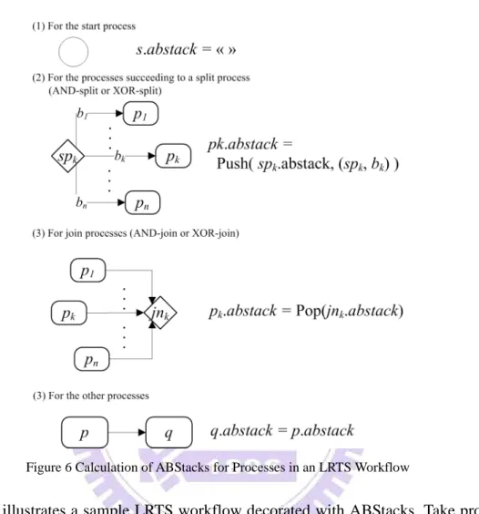
Figure 6 illustrates how push and pop functions work for the calculation of the ABStacks
corresponding to the processes in an LRTS workflow.
Figure 6 Calculation of ABStacks for Processes in an LRTS Workflow
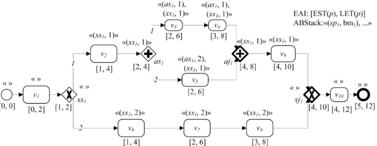
Figure 7 illustrates a sample LRTS workflow decorated with ABStacks. Take process v5
for example. The items (as1, 2), and (xs1, 1) in the ABStack of v4 shows that v4 resides on #2
branch split from the AND-split process as1 and #1 branch split from the XOR-split process xs1.
The order of (as1, 2) and (xs1, 1) indicates that the parallel structure started from as1 is nestedly
Figure 7 A Sample TS workflow with ABStacks and EAIs
Besides, the structural items (as1, 1) and (as1, 2) in the ABStacks of v4 and v5
correspondingly indicate that v4 and v5 reside on different branches split from AND-split
process, as1. In other words, v4 and v5 are parallel. The parallelism or exclusiveness between
processes can be identified through comparing the ABStacks of the corresponding processes,
and Lemma 2 shows how ABStacks work for identification of structural relationships between
processes in an LRTS workflow.
Lemma 2
For an LRTS workflow w, and p, q∈Pw
(1) Parallel(p, q) holds if and only if
∃(sp, bm)∈p.abstack and (sp, bm’)∈q.abstack where sp∈Pw, sp.type == AS and
bm ≠ bm’.
(2) Exclusive(p, q) holds if and only if
∃(sp, bm)∈p.abstack and (sp, bm‘)∈q.abstack where sp∈Pw, sp.type == XS and
bm ≠ bm’.
Proof:
Consider the if-part of statement (1), according to Definition 6, if ∃(sp, bm)∈p.abstack
and (sp, bm’)∈q.abstack where sp∈Pw, sp.type == AS and bm ≠ bm’, there exists a process m
that bm == (sp, m), and m is either equivalent to p or Reachable(m, p) holds. Similarly, there exists another process n for q. bm ≠ bm’ indicates that m ≠ n, and p and q reside on different branches split from the AND-split process, sp. Thus Parallel(p, q) holds and the if part is shown correct.
As for the only-if-part, if Parallel(p, q) == true, p and q reside on different branches of a parallel structure. Let sp be the AND-split process starting the parallel structure, and jn be the
AND-join process terminating it. The nodes in the path from sp to p are totally different from those in the path from sp to q. Besides sp and jn, two distinct paths, <sp, …, p, …, jn> and <sp, …, q, …, jn>, exist. Therefore, there exists a process m that (sp, m)∈Fw and either m is
equivalent to p or Reachable(m, p) == true. Similarly, there also exists such a process n for q.
m and n can not be the same process because they reside on different branches split from sp,
and thus, BM(sp, m) ≠ BM(sp, n). According to Definition 6, (sp, BM(sp, m)) is included in
p.abstack, and (sp, BM(sp, n)) is included in q.abstack. The only-if part of statement (1) of
the lemma is proved.
Part (2) can be proved similarly and the proof is omitted here. With the paragraphs above, Lemma 2 is shown correct.□
2.4.3 Analysis of Twisted Temporal and Structural Relationships between Processes in LRTS
workflow
In a TS workflow, the temporal and structural relationships between processes are twisted.
This section firstly shows how to identify the temporal property between processes.
Figure 8 The Temporal Relationships between Time Intervals [39]
A time interval is duration of a segment of time. In [39], Allen defines seven reasoning
relationships between time intervals. Figure 8 illustrates the temporal relationships adopted in
definition of time intervals and the temporal relationships between time intervals adopted in
this dissertation.
Definition 7 (Time Intervals)
A time interval ti = [S(ti), E(ti)] indicates a duration from the time point S(ti) to E(ti), E(ti)≥S(ti).
A time point tp can be represented as a time interval [tp, tp], and ctime is the time point indicating the current time.
For any two time intervals ti1 and ti2,
ti1 is before ti2, notated as ti1pTIti2, if and only if E(ti1)≤S(ti2).
ti1 is after ti2, notated as ti1fTIti2, if and only if ti2 is before ti1.
ti1 overlaps ti2, notated as ti1≈TIti2, if and only if
MIN({E(ti1), E(ti2)}) – MAX({S(ti1), S(ti2)}) > 0
ti2 contains ti1, notated as ti2⊇TIti1, if and only if S(ti2)≤S(ti1) and E(ti2)≥E(ti1).
In Definition 7, two utility functions MAX and MIN are invoked. Function MAX returns
the element with the maximum value among the parameter set, and function MIN returns the
minimal one.
In [23] and [40], Joshi et al use not only individual time intervals but also the periodic
temporal expressions to describe the temporal constraints in roles for temporal RBAC model.
For example, the expression “the night time duty is activated 6pm to 11pm every Wednesday
and Friday” indicates that the permissions for night time duty are activated during certain
repeated time durations. The periodic temporal expressions can be viewed as a combination of
multiple time intervals, and are grouped as a time description as following definition.
Definition 8 (Time Descriptions)
A time description td is a set of time intervals. For any two time intervals tiz and tiy
in td, tix and tiy are exclusive. On the other hand, for any two non-empty time
description tda and tdb, tda contains tdb notated as tda⊇TDtdb if and only if
Figure 9 Calculation of EAIs in an LRTS Workflow [34][37]
In [34] and [37], the minimum and maximum working durations are used to estimate the
active duration of a process corresponding to the start of workflow. The Estimated Active
Interval (EAI) of a process is a time interval indicating when the process can be initialized and
when it should be terminated. In this dissertation, the Estimated Active Interval of a process p,
notated as EAI(p) is defined as following:
Definition 9 (Estimated Active Interval) For a TS workflow w and a process p∈Pw,
EAI(p) = [EST(p), LET(p)], and corresponding to when w starts: EST(p) indicates the earliest time that p can be initialized. LET(p) indicates the latest time that p must terminate.
With the assumption that the EST and LET of the start process of a TS workflow are zero,
the methodology described in [34] and [37] is adopted to calculate the EAIs of processes in an
LRTS workflow as Figure 9 illustrates.
With Lemma 1 and Lemma 2, whether two processes in an LRTS workflow are
exclusive, parallel, or reachable from one to the other is identified with corresponding
the corresponding EAIs, and the following lemmas show how EAIs can be adopted in
analysis of LRTS workflow.
Lemma 3
For an LRTS workflow w, p and q∈Pw, q.type == ACT,
if Reachable(p, q), LET(p) < LET(q) Proof:
Reachable(p, q) represents that the path <p, m1, m2, …, mn, q> exists. Now we prove the
lemma with mathematical induction. For n = 0, (p, q)∈Fw, since q.type = ACT, D(q) > 0 and
LET(q) = LET(p) + D(q). LET(p) < LET(q) holds. Hypothesis: The lemma holds when n < k.
For n = k, LET(q) = LET(mk) + D(q) and LET(mk) < LET(q). According to the
construction rule of TS workflow, mk.type ≠ S, E, and mk.type∈{AS, XS, AJ, XJ, ACT}. The
following conditions should be discussed:
For any 1≤i≤k, if there exists an mi where mi.type = ACT, according to the hypothesis,
LET(p) < LET(mi) and LET(mi) < LET(q). Therefore, LET(p) < LET(q). Otherwise, for any
1≤i≤k, mi.type∈{AS, XS, AJ, XJ}, according to the EAI calculation methods, for any (u, mi)
∈Fw, LET(u)≤LET(mi). Since there exists a path from p to mi, LET(p)≤LET(mi). On the
other hand, according to the hypothesis, LET(mi) < LET(q). Therefore, LET(p) < LET(q).
With statements above, we know the lemma holds for n = k, and on the basis of mathematical induction, Lemma 3 is proved. □
Lemma 4
For an LRTS workflow w, p and q∈Pw, p.type == q.type == ACT,
if Parrallel(p, q) == Exclusive(p, q) == false, and LET(p) < LET(q), Reachable(p, q) == true.
Lemma 4 can be shown correct with Lemma 1 and the construction rule of LRTS
workflow. Lemma 4 describes that if two activity processes in an LRTS workflow are not
mutually parallel or exclusive, the process with larger LET is reachable from the process with
smaller LET. From Lemma 1, we know that in an LRTS workflow, two processes are either
parallel, exclusive, or reachable from one to the other. Therefore, Lemma 4 can be re-stated as
Lemma 5 that if two activity processes in an LRTS workflow are reachable from one to the
Lemma 5
For an LRTS workflow w, p, q∈Pw, p.type == q.type == ACT,
If (Reachable(p, q)⊕Reachable(q, p)) == true, and LET(p) < LET(q), Reachable(p, q) == true.
On the other hand, two processes are concurrent if and only if they are structurally parallel
and overlapped in EAIs. On the basis of Lemma 5, a process is before another one if one of the
following statements holds, (1) the latter is structurally reachable from the former, and (2) they
are structurally parallel and the EAI of the former is before the EAI of the latter. The definition
of the structural and temporal relationships in LRTS workflow is formally described as
following.
Definition 10 (Structural and Temporal Relationships in LRTS workflow) For an LRTS workflow w,
Concurrent: Pw×Pw⇒{true, false}
Concurrent(p, q) == true if and only if
( Parallel(p, q)∧EAI(p)≈TIEAI(q) ) == true.
Before: Pw×Pw⇒{true, false}
Before(p, q) == true if and only if
( Reachable(p, q)∨( Parallel(p, q)∧EAI(p)pTIEAI(q) ) ) == true.
After: Pw×Pw⇒{true, false}
Chapter 3. A Delegation Framework for WfMS based on
Task-Role based Access Control and TS workflow
Tasks represent the basic logical steps of business processes, and roles combining users
with similar responsibility together are the core components for access control management in
modern WfMS. With both tasks and roles as core concept, we introduce a delegation
mechanism for WfMS coordinated with TRBAC. In section 3.1, TRBAC and the issues related
to delegation in WfMS are sketched. The task and role models adopted in this dissertation are
described in section 3.2, and our delegation framework for WfMS and TRBAC is depicted in
section 3.3. In section 3.4, a case study is made, and the related works are discussed and
compared with our methodology in section 3.5.
3.1 Background
3.1.1 Task-Role based Access Control Model
Based on RBAC96 [15][16], TRBAC model [17] illustrated in Figure 10 works for
modern enterprise environments in which tasks are the fundamental units of business processes.
TRBAC model binds permissions on tasks and groups users operating the same tasks into roles.
Rather than accessing business objects directly [15][16], users accomplish their works through
tasks in which permissions are properly defined and protected. Restricting the access rights of
business objects on tasks facilitates permission management and reduces the risks of
inappropriate permission authority made by users. In TRBAC [17], tasks are classified into four
classes according to whether the task participates in a business process and whether the task is
inherited by the ancestor job. The classes of tasks in TRBAC model are illustrated in Table 1.
Table 1 Classes of Tasks in TRBAC Model [17]
Non-inheritable Inheritable Passive access P (private) S (supervision)
Active access W (workflow) A (approval) 3.1.2 Delegation Approaches in RBAC and TRBAC
Delegation is to authorize subjects like access rights or works between users or roles, and
is often built based on access control models. The user (or role) authorizing the subject is the
delegator, and the one who receives it is the delegatee. In RBAC [15][16], permissions to
business objects, like documents or devices, etc. are bound with roles. RBDM0 [19] provides a
flexible way for granting and revoking permissions between roles. RBDM1 [20], an extension
of RBDM0 [19], is more realistic since it organizes roles with hierarchy. Both techniques are
focused on delegation of roles among human users through identifying can-delegation
relationships between roles.
In [21], the essence of this delegation model is that a user delegates a particular right to
another user, and delegation of partial permissions is allowed. Osborn separates users in
organization, role hierarchies, and relationships among privileges into different graph models in
role. In [18], Crampton gives a further discussion about both granting and transferring access
rights between roles. When access rights are granted from the delegator to the delegatee, the
delegated access rights are available for both the delegator and the delegatee [18]. On the other
hand, if the access rights are transferred, only the delegatee holds the access rights after the
delegation [18]. Besides, Crampton considers both can-delegate and can-receive relationships,
and introduces the concept of administrative scope to improve the efficiencies in delegation
controlling [18].
Besides, tasks, the basic logic units of business processes, should also be considered in
delegation. In [18], Crampton addresses the issues like upward delegation and authorization of
appropriate permissions for delegation to adopt RBAC-based delegation mechanism in
task-based WfMS. Bammigatti associates tasks into permission management and develops a
new model for using RBAC in workflow system [42]. In TAC model [43], the permissions
possessed by roles and required by tasks are described separately, and the assignment of tasks to
roles is thus constrained. With such constraints, a protocol enabling delegation of task instances
from users to roles is established [43].
TRBAC [17] binds the permissions with tasks, and the tasks with roles. With the roles
assigned to users, users access business objects and accomplish their duties through tasks.
Therefore, authorization of permissions is not necessary for delegation of tasks and task
instances in TRBAC. In our previous work [24], a delegation framework for TRBAC has been
initially established without considering the temporal issues. Zhang et al. develops a delegation
model for time constraints-based TRBAC [44]. However, Zhang reduces TRBAC model as
TRBACM model in which permissions and tasks are separately bound with roles. In [44], users
delegate permissions together with tasks to accomplish their works, and the methodology
3.1.3 Separation of Duty
Separation of Duty (SOD) is a security principle which requires multiple users to be
responsible for the completion of a work [45]. Since delegation transfers permissions and tasks
among users, the delegation approaches also follows the SOD policy of the corresponding
access control system. In RBDM1 [16], Ferraiolo defines SOD as “For a particular set of
transactions, no single individual is allowed to execute all the transactions within the set.”
Botha discusses SOD in workflow environments both statically and dynamically [46]. In
Botha’s study, four possible conflicts, conflicting roles, conflicting permissions, conflicting
users, and conflicting tasks, are described, and the corresponding methods for the conflicts are
developed.
TRBAC [17] offers SOD policy at both task and instance level, and defines that some tasks
are mutually-exclusive to each other. In task level SOD, for the roles played by a user, none of
the tasks assigned to the roles are mutually-exclusive. In instance level SOD, the policy is
effective for the tasks belonging to the same workflow instance. The task instances instantiated
from the mutually-exclusive tasks in a workflow instance can not be executed by the same user
[17]. In this dissertation, we follow the SOD policy established in TRBAC when delegation.
3.2 Task and Role Model
Tasks are the basic components describing pieces of works in logical steps within a
workflow [1], and are modeled as activity processes in TS workflow model. Permissions are
the rules describing the admission in accessing business objects such as documents or
computation resources. In this dissertation, individual permissions are bound with tasks on the
basis of TRBAC. Besides, it is assumed that only the tasks related to enactment of workflows
can be delegated during run-time, and therefore, only “Workflow” and “Approval” are
Definition 11 (Task)
For a TS workflow w, Tw = {t | t∈Pw, t.type == ACT} is the set of tasks in w.
Let T be the set of all the tasks managed by WfMS,
Tw⊆T, ∀t∈T, the following properties are additionally modeled:
Pt is the set of permissions to business objects bound on t.
Rt is the set of roles assigned to t.
t.class∈{Workflow, Approval} is the class of t.
During run-time, TS workflow instances are instantiated from a TS workflow, and the
tasks in the TS workflow are also instantiated as Task Instances. Task instances are the basic
units for daily duties. When a task instance is going to be executed, the system offers the
instance to a role in accordance with the corresponding TS workflow. Then, the instance is
allocated to the work list of one of the users playing the offered role. The user executes the
instances in his work list, and submits the instance whenever it is complete. A task instance is
suspended once the responsible user becomes unavailable for a certain time, and is resumed
from suspension when the responsible user is again available. A task instance is failed if it is not
completed in its active interval, and is discarded if it is not executed until the end of the TS
workflow instance. The active interval of a task instance is obtained from the EAI of its source
task and the starting time of the TS workflow instance, and indicates when it can be started and
the corresponding deadline. TS workflow instance and task instances are modeled as following.
Definition 12 (TS workflow Instance and Task Instance) A TS workflow instance wi = (w, Iwi, st).
w is the TS workflow instantiating wi
Iwi is the set of the task instances instantiated from the tasks in Tw.
Let I be the set of all the task instances managed by WfMS. Iwi⊆I, ∀i∈Iwi, i = (wi, tk, ar, s, eu, ai).
tk∈Twi.w is the task instantiating i.
ar∈Rtk is the role i offered.
s∈{Initiated, Discarded, Offered, Allocated, Completed, Suspended, Failed} is the status of i.
eu is the user executing the task instance.
ai = [wi.st + EST(tk), wi.st + LET(tk.eai)] is the active interval of i. st is the time point wi being initialized.
Users are the participants of business processes. A user may play multiple roles for various
businesses, and a role can be played by multiple users also. During run-time, users execute task
instances in their work list to accomplish their daily duties. The status of a user is normally
available and is transited to unavailable when he/she is not available for work. A user is
formally modeled as following.
Definition 13 (User)
Let U be the set of all the users managed by WfMS. ∀u∈U, u = (Ru, WL, cs).
Ru is the set of roles played by u.
WL = { i | i∈I, i.eu = u, i.s∈{Allocated, Completed, Suspended, Failed} } is the work list of u.
cs∈{Available, Unavailable} is the current status of u.
Roles represent the collections of users with common responsibilities [15][16]. In this
dissertation, a role is modeled as a collection of the users responsible for the same tasks with
certain timing constraints. The definition roles are formally described as follows.
Definition 14 (Role)
Let R be the set of all the roles managed by WfMS. ∀r∈R, r = (Ur, Tr, etd).
Ur is the set of users playing r.
Tr is the set of tasks assigned to r.
etd is a time description indicating when r is active.
Roles are organized with the role hierarchy. The role hierarchy indicates inheritance
relationships and partial orders between roles to reflect the organization lines of authority or
responsibility [15]. In this dissertation, the role hierarchy is modeled with directed acyclic
graph (DAG) like in [15], [47], and [48]. Among the role hierarchy, the roles in higher positions
possess larger authority, and the connected roles are more coherent than disconnected ones
[15][47][48]. The number of edges between two connected roles in the role hierarchy is defined
as their distance. The roles closer in distance are related more tightly than roles farther. The role
in the following definition.
Definition 15 (The Role Hierarchy) The role hierarchy RH⊆R×R.
∀(r1, r2)∈RH, (r1, r2) shows a partial order that all inheritable tasks assigned to
r1 can also be assigned to r2.
∀r, r’∈R, r’frh r holds if there exists (r, r1), .., (rk, r’)∈RH*.
RH is acyclic, and if r’frh r holds, rfrh r’ does not.
DisRH() shows the distance between two roles in the role hierarchy: (1) DisRH(r, r) = 0,
(2) if r’frh r, DisRH(r, r’) = -(k+1) and DisRH(r’, r) = k+1,
(3) DisRH(r, r’) is undefined while neither r’frh r nor rfrh r’ holds.
3.3 Delegation Framework for WfMS on TRBAC
3.3.1 The properties of Delegation
A delegation is primarily composed of a delegator, a delegatee and a delegating subject. In
TRBAC, since the permissions are bound with tasks, the task instances are delegated between
users during run-time. For each delegation, the delegator, the delegatee, the delegated task
instance, and the delegation duration are recorded in a delegation record. In this dissertation, the
duration is constrained not exceeding the active interval of the delegated task instance. Our
framework allows multi-level delegation [19][21], and a task instance might be delegated
several times. For each delegated task instance, a delegation record keeps tracking its status no
matter how many times it is delegated. All the delegators who once delegated the task instance
are put into the historical delegator list in the corresponding delegation record.
Besides, we assume that the maximal times that a task instance can be delegated are
constrained by an enterprise policy named the Maximal Levels of Delegation (MLD). MLD is a
non-negative integer. If MLD is equal to 1, multi-level-delegation is forbidden. With above
features, the format of a delegation record is defined in Definition 16. When a delegation occurs,
Definition 16 (Delegation Record)
Let D be the set of all the delegation records managed by WfMS.
∀d∈D, d = (di, dr, de, dur, HDRL).
di is the delegated task instance, and ∀d’∈D, if d’≠d, d’.di≠d.di. dr∈U is the original delegator.
de∈U, is the current delegatee.
dur is a time interval indicating during when d is effective, and di.ai⊇TIdur.
HDRL = {u1, u2, …, uk} is the historical delegator list. u1 == dr, and
∀um∈HDRL, m<k, um delegated di to um+1, and uk delegated di to de.
|HDRL|≤MLD.
Definition 17 (Delegation Records in Task Instances)
For any task instance i, if i is delegated, i.dr∈D, i.dr.di == i; otherwise, i.dr == Ø. Algorithm 1 describes how a task instance is delegated in our framework.
Algorithm 1 Delegation Algorithm - DA Input: the delegating task instance dti,
the delegatee u, and
the designated delegating duration ddur Pre-Condition: dti.ai⊇TIddur
DA {
01:if (dti.dr ≠ Ø) {
02: if( |dti.dr.HDRL|+1 > MLD )
03: EXCEPTION( MAX_DELEGATION_LEVEL_REACHED );
04: else {
05: add dti.eu to dti.dr.HDRL; 06: dti.dr.dur = ddur;
07: dti.dr.de = u; 08: }
09:} else {
10: dti.dr = (dti, dti.eu, u, ddur, {dti.eu}); 11: add dti.dr to D;
12:}
13:remove dti from dti.eu.WL; 14:add dti to u.WL;
15:dti.eu = u;
The system invokes Algorithm 1 when delegating a task instance to the designated
delegatee. At line 1, the algorithm checks whether the input task instance has been delegated. If
so, the algorithms checks the size of historical delegator list of the task instance at line 2 to
assure that the delegation does not violate the restriction held by MLD. According to the input
parameter, the delegation record is updated from line 5 to 7. Otherwise, the task instance is
delegated for the first time. A new delegation record is created and attached to dti at line 10 and
11. After the delegation record is well updated or created, the task instance is transferred from
the delegator’s work list to the delegatee’s from line 13 to 15
3.3.2 Delegatee Decision
Algorithm 1 does not concern whether a delegatee is appropriate for delegation or not. In
multi-level-delegation, if a task instance is delegated to one of the delegators who once
delegated the task instance, a delegation loop occurs. Delegation loop causes redundancy in
business and should be avoided [49]. Algorithm 2 is constructed to remove users inducing
delegation loop from the candidate users.
Algorithm 2 Removing Users Causing Delegation Loop - RUDL Input: the candidate user set CUS, and
the target task instance ti Pre-Condition: CUS⊆U User Set RUDL { 01:if (ti.dr ≠ Ø)
02: CUS = CUS \ ( ti.dr.HDRL ); 03:return CUS;
}
Taking a set of users and a task instance as the input parameters, Algorithm 2 eliminates
users causing delegation loop from the input user set. Each delegator user who once delegated
the instance is recorded in the historical delegator list of the delegation record. After removing

![Figure 8 The Temporal Relationships between Time Intervals [39]](https://thumb-ap.123doks.com/thumbv2/9libinfo/8016833.160664/28.892.149.722.503.973/figure-temporal-relationships-time-intervals.webp)
![Figure 9 Calculation of EAIs in an LRTS Workflow [34][37]](https://thumb-ap.123doks.com/thumbv2/9libinfo/8016833.160664/30.892.224.717.119.489/figure-calculation-eais-lrts-workflow.webp)
![Figure 10 The TRBAC Model [17]](https://thumb-ap.123doks.com/thumbv2/9libinfo/8016833.160664/33.892.154.784.504.1110/figure-the-trbac-model.webp)
