國
立
交
通
大
學
多媒體工程研究所
碩
士
論
文
以 視 覺 為 基 礎 之 視 障 輔 助 導 引 系 統
A Vision-based Navigation System for Visually Impaired People
研 究 生:張筱苑
指導教授:陳永昇 教授
以視覺為基礎之視障輔助導引系統
A Vision-based Navigation System for Visually Impaired People
研 究 生:張筱苑 Student:Xiao-Yuan Chang
指導教授:陳永昇 Advisor:Yong-Sheng Chen
國 立 交 通 大 學
多 媒 體 工 程 研 究 所
碩 士 論 文
A ThesisSubmitted to Institute of Multimedia and Engineering College of Computer Science
National Chiao Tung University in partial Fulfillment of the Requirements
for the Degree of Master
in
Computer Science
January 2011
Hsinchu, Taiwan, Republic of China
致
致
致謝
謝
謝
首先,我要感謝指導老師陳永昇教授,老師的研究態度與為人處 事,都是我想學習的楷模,謝謝老師這些日子來用心的指導我研究以 及論文寫作,令我受益匪淺。感謝BSP實驗室提供一個良好的學習環 境,我很喜歡大家熱愛討論分享,互相關心幫忙的歡樂氣氛。感謝監 控組的學長詠成、發哥、sheep與學弟妹乙宛跟旭龍,你們適時的給予 建議與討論,使我收穫良多。兩年多的研究生活點滴歷歷在目,感謝 交大讓我在這裡成長茁壯,使我在各方面都更加精進。非常感謝柏志 一路以來的陪伴,在我遭遇挫折能鼓勵我,並且時常與我一起討論和 研究問題。感謝我的父母家人,謝謝你們對我的不吝付出以及關心, 非常感謝你們。最後,謝謝所有曾經幫助過我的人,讓我能夠順利完 成此篇論文。中
中
中文
文
文摘
摘
摘要
要
要
我們致力於發展一套以電腦視覺方法為基礎之視障輔助導引系統, 系統的目的是提供視障朋友們一個行走至目的地的導航資訊,包含 要走多少距離以及要轉多少角度。我們系統提供以下功能:語音輸 入辨識介面和導航指引。導航指引包括規畫路徑,提供點對點的導 引,以及行走方向監控。 在系統的實作方法方面,我們事先建立包 含定點的地理位置、地圖、環場圖的資料庫。接著利用GPS測量使用 者最初所在的位置,並藉由語音辨識得知使用者想到達的目的地,利 用Dijkstra的演算法,規劃出一條最短路徑。我們系統提供點對點的導 引資訊,包含到下一個定點距離還要走多遠,以及要轉的角度資訊。 我們使用GPS測量到的座標以及TWD97座標系統去做距離計算,並利 用SURF的演算法去做影像的比對,最後算出要轉的角度。我們並利用 手機上的電子羅盤跟GPS來監控使用者行走的方向,若有偏離則會發 出警告給使用者。結果顯示,以電腦視覺方法為基礎的視障輔助導引 系統具有較穩定的效能。我們希望這個系統對視障朋友來說,在日常 生活中能有所助益。Abstract
This work proposes a vision-based navigation system for visually im-paired. This system provides the following functions: speech interface and navigation guidance including path planning, point-to-point guidance, and path monitoring. We use the following method to implement the system. First, we construct a panoramic database at a set of specific locations. Next, we use the Dijkstra’s algorithm to calculate the shortest path according to the current position and the destination of the user. The point-to-point guidance contains the remaining distance computed from the GPS locations, and the turning degree computed by image matching method, the SURF algorithm. Finally, we use the digital compass and GPS to monitor the facing direction of the user. The results show that the proposed vision-based navigation sys-tem is more stable then digital compass. We hope our syssys-tem can improve the daily lives for visually impaired people.
Contents
致 致 致謝謝謝 v 中 中 中文文文摘摘摘要要要 vii Abstract ix 1 Introduction 1 1.1 Background . . . 21.2 Survey of navigation system for visually impaired . . . 2
1.3 Thesis organization . . . 4
2 Proposed Vision-based Navigation System 5 2.1 System overview . . . 6
2.1.1 Functions of the proposed system . . . 7
2.1.2 Usage procedure for the proposed system . . . 8
2.2 System development platform . . . 10
2.2.1 Hardware for the proposed system . . . 10
2.2.2 Software for the proposed system . . . 10
3 Method 15 3.1 Introduction to navigation method . . . 16
3.2 Panoramic database construction . . . 17
3.3 Path planning . . . 18
3.4 Image matching . . . 21
3.5 Distance and orientation estimation . . . 22
3.5.1 Distance estimation . . . 22
3.5.2 Calculation of turning degree . . . 23
3.5.3 Orientation calibration . . . 24
4 Experimental Results 27 4.1 The domain of the panoramic database and testing data . . . 28
4.2 Results for vision-based navigation system and system Performance . . . 29
4.2.1 Accuracy of image matching . . . 29
4.2.2 The demonstration of vision-Based navigation system . . . 31
4.3 System performance . . . 34
5 Conclusions 41 5.1 Discussions . . . 42 5.2 Conclusions . . . 43 Bibliography 45
List of Figures
1.1 The population and the proportion of visually-impaired . . . 2
1.2 The UCSB Personal Guidance System. (Figure source: [6]) . . . 3
1.3 Drishti: outdoor mobile user(left) and indoor mobile user(right). (Figure source: [9]) . . . 3
1.4 Indoor Wayfinding.(Figure source: [3]) . . . 4
2.1 The overview of the proposed vision-based navigation system . . . 6
2.2 The usage procedure of the proposed system . . . 9
2.3 The mobile phone: HTC desire . . . 10
2.4 The Architecture of Android. (Figure source: [1]) . . . 11
2.5 SQLite classes in Android . . . 12
2.6 The interface of developing a program in Eclipse . . . 13
3.1 The example for using speech input (Figure source: [2]) . . . 16
3.2 The situations of path monitoring . . . 18
3.3 The equipment for taking pictures to generate panoramic images . . . 19
3.4 The example of generating a panoramic image . . . 19
3.5 The diagram of graph in the map . . . 20
3.6 The calculation of the matching center point . . . 23
3.7 The calculating process of turning degree. . . 24
3.8 The two different GPS position 1 and 2. . . 25
3.9 The calibration of GPS and compass. . . 25
4.1 The corresponding panoramic images in the database in the map. . . 28
4.2 The region of the test data for our experiment. . . 29
4.3 The testing data for region A. . . 30
4.4 The testing data for region B. . . 31
4.5 The testing data for region C. . . 32
4.6 The image matching result by SURF algorithm. . . 32
4.7 The example of wrong mapping. . . 33
4.9 The demonstration of the proposed system. . . 34
4.10 The system demo result . . . 35
4.11 The system demo result . . . 36
4.12 The system demo result . . . 37
4.13 The variance of GPS. . . 38
4.14 The variance of using Compass . . . 38
4.15 The matching result for the proposed system. . . 39
4.16 The matching result for the proposed system. . . 40
5.1 The example of non-static region and illumination change. (a)Cars (b)Moving people and cars (c)Trees (d)Illumination change. . . 42
List of Tables
3.1 The transforming result for WGS84 and TWD97 datum of positions 1 and 2. 23 4.1 The accuracy for different region A, B, and C. . . 31 4.2 The image matching time for each panoramic image. . . 38 4.3 The comparison between the proposed system and the digital compass. . . 40
Chapter 1
Introduction
1.1
Background
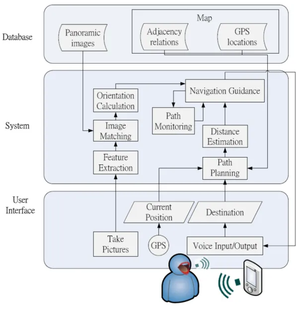
According to Statistics Department under the Ministry of the Interior, there are ap-proximately 56 thousand visually impaired people in 2009 in Taiwan. As shown in the chart in Figure 1.1, the number and proportion of the population of visually impaired are increasing every year. Therefore, it is important to strengthen the independence of this community.
Figure 1.1: The red and green lines indicate the number and the proportion of the visually impaired in Taiwan, respectively.
While walking in an unfamiliar environment, the visually impaired must rely on some kind of assisted facilities, such as guide dogs and white canes. However, these facilities have some limitations, such as high costs or heavy weights. Therefore, we aim to develop a navigation system which can guide the visually impaired to their final destinations. We plan to implement this system on mobile phones because of their universality and portability. In addition to the GPS and digital compass on the mobile phone, we plan to develop a vision-based method to provide the guidance to the visually impaired.
1.2
Survey of navigation system for visually impaired
There are many researches on navigation systems. In general, navigation system for visually impaired can be divided into three categories: indoor [11], outdoor [12] [5], and indoor and outdoor environments [6] [9]. We focus on outdoor environments which can
be separated into two parts: micro navigation and macro navigation.
Micro navigation technologies provide assistance through immediate environment. Among various kinds of Electronic Travel Aids (ETAs), obstacle avoidance systems have been designed to assist visually impaired travellers for micro navigation, such as ultra-sonic obstacle avoiders [7] and Laser Cane [8]. Macro navigation technologies provide assistance through the distant environment. Global Positioning Systems (GPS) and Ge-ographical Information Systems (GIS) have been used to develop macro navigation. For examples, UCSB Personal Guidance System [6] project has been focused on designing the user interface and the GIS component from 1985. As shown in Figure 1.2, one person is walking with the assistance from their original system developed in 1993.
Figure 1.2: The UCSB Personal Guidance System. (Figure source: [6])
Functioning in both indoor and outdoor environments, Drishti [9] system provides users with vocal notifications to avoid obstacles(Figure 1.3).
Figure 1.3: Drishti: outdoor mobile user(left) and indoor mobile user(right). (Figure source: [9])
Another system, ”Indoor Wayfinding” [3], was proposed by Liu et al and can pro-vide users with point-to-point guidances(Figure 1.4). When the user arrives at a specific location, the system will continue to provide the guidance to the next point.
Figure 1.4: Indoor Wayfinding.(Figure source: [3])
1.3
Thesis organization
The remainder of this thesis is as follows. We describe the system overview and plat-form of vision-based navigation system in Chapter 2. Chapters 3 and 4 show the method we developed in our system and the experiment results, respectively. Finally, Chapter 5 presents our conclusions.
Chapter 2
Proposed Vision-based Navigation
System
2.1
System overview
In this work, we propose a system which can provide visually impaired people naviga-tion guidances toward their destinanaviga-tions. The overview of the proposed system is shown in Figure 2.1.
Figure 2.1: The overview of the proposed vision-based navigation system
While walking in an unfamiliar place, our system will get the GPS locations and tell visually impaired people where they are. Futhermore, they can input their destination via voice, and our system will provide navigation guidances while walking toward their goals. The navigation guidances contain path planning, point-to-point guidance, orienta-tion calculaorienta-tion, and path monitoring. For the path planning and point-to-point guidance, our system constructs a database which consisting a map and panoramic images. The Map contains GPS locations, adjacency relations for a set of positions, called stations in
this work. Our system will compute a shortest path according to the current position and the goal of the user, and tell users how far to walk to next position in the shortest path. In the orientation calculation, users can take pictures with their mobile phones, and the system will match the taken images with the panoramic images in the database. In the path monitoring, our system can track the movements of users and give notification when users reach to a station or the destination. If the user deviates from the planned path, our system will give warnings and suggestions to the user. The navigation guidances are all based on voice inputs and outputs for visually impaired people. The following shows the details about functions and operations of the system.
2.1.1
Functions of the proposed system
Vision-based navigation system provides the following functions: speech interface, navigation guidances including path planning, point-to-point guidance, distance estima-tion, orientation calculaestima-tion, and path monitoring.
Speech interface Speech interface is appropriate for visually impaired people to op-erate the mobile phones as well as the proposed vision-based navigation system. Speech recognition and speech notification are supported in our system. We use voice recognition to understand the requests from users and voice notification to let users know the replies, the warnings, and the results. Therefore, the system is easy to use for visually impaired people.
Navigation guidance The navigation guidance of our system contains five part: path planning, point-to-point guidance, distance estimation, orientation calculation, and path monitoring.
In the path planning, our system can calculate the shortest path in the map of the database from the current position to the destination requested by the user. The shortest path includes the starting position, several stations along the path, the destination, and pathways connecting each pair of neighbor stations. Then the user can follow the planned path to start traveling toward the goal.
Unlike most of guidance systems designed for normal people, our system focuses on helping visually-impaired people. As the result, we propose point-to-point guidance as the guiding manner. In the point-to-point guidance, we only guide user to the nearest station instead of the remaining path to the destination, because it is easier for visually-impaired people to follow. The further guiding information will be provided when they reach the next station.
In the procedure of the distance estimation, vision-based navigation system can track the position of the user by GPS sensor. According to the information of the stations and the pathways in the database, our system can estimate the distance between current position and the next station in the shortest path. Hence, the user can be notified the remaining distance to the next station.
In the orientation calculation, the user can take a forward-facing picture by the mobile phone, said the query image, then vision-based navigation system will process the image to calculate the facing orientation of the user. Our system first extracts the features from the query image and matches the query image with the panoramic images in the database. Then it calculates the image matching ratio of the panoramic image as the facing direction of the user. Next, our system computes the direction from the current position to the next station. By comparing this direction with the facing direction of the user, our system can guide the user how to change the facing direction toward the next station.
In the path monitoring, vision-based navigation system tracks the movements of users and detects the current position of the user. If the user deviates from the planned path, the system will give warnings. If the user arrives at each accurate station or destination, our system will give notification to the user.
2.1.2
Usage procedure for the proposed system
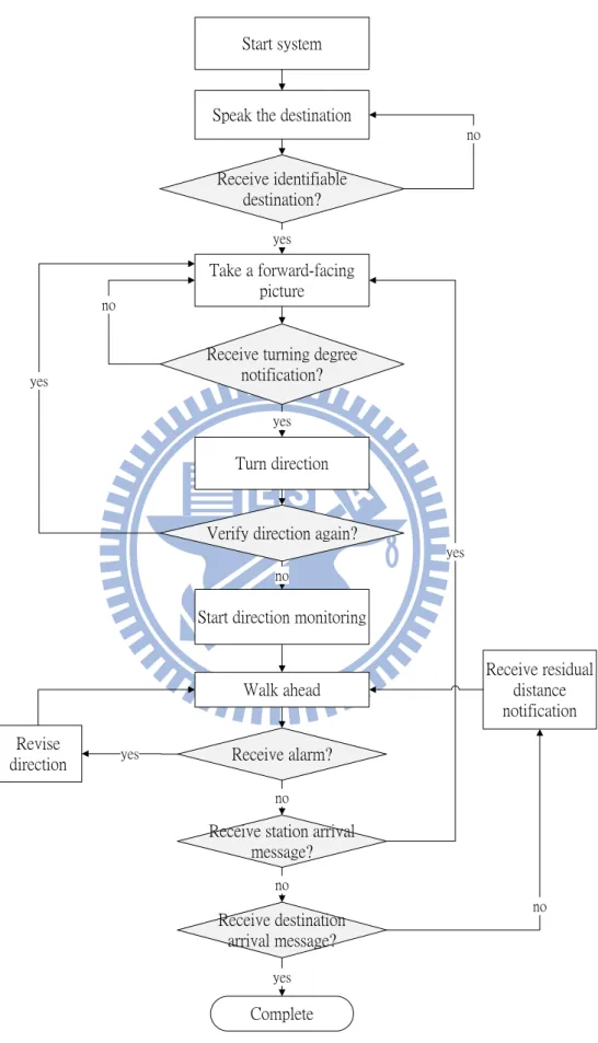
The flowchart of the system shown in Figure 2.2 describes the usage of procedure for our system. In the flowchart, the instructions which the user needs to follow are shown in rectangle boxes, and the replies of the system are shown in the decision boxes.
At the beginning, the user starts the vision-based navigation system and the system records the current position by GPS/AGPS. Therefore our system can record the initial position of the user.
Second, press the volume down button to start voice recognition. The user can speak out his/her destination to vision-based navigation system. If the user receives correct destination from the system, then goes to the next step. Otherwise, the user can repeat his destination via voice.
Third, press the volume down button to take a forward-facing picture. If the user receives the turning degree notification from the system, then turns direction. Else press the same button to take a forward-facing picture again.
Fourth, after turning to the direction, the user can verify the direction again. Press the volume up button to take a forward-facing picture and get the accurate turning degree.
Fifth, press the volume down button to start direction monitoring and walk ahead. If the user receives alarm, it means the user deviates from the path. Then the user needs to revise his/her direction by rotating horizontally until the alarm is disappeared.
Start system
Speak the destination
Take a forward-facing picture
Revise
direction Receive alarm?
Receive station arrival message? Receive destination arrival message? Complete yes no no no yes
Start direction monitoring Receive identifiable
destination?
no
yes
Receive turning degree notification?
no
yes
Turn direction
Verify direction again?
yes no Walk ahead yes Receive residual distance notification
Next, if the user does not receive the station arrival message, then go the next step. Else, press the volume down button to start taking a forward-facing picture iteratively.
Final, if the user does not receive the destination arrival message, then the system shows residual distance notification via voice. Else, arrive at the destination, and the navigation guidance is complete.
2.2
System development platform
2.2.1
Hardware for the proposed system
The hardware we use is the HTC desire mobile phone shown in Figure 2.3. The fol-lowing list the detailed specifications:
Figure 2.3: The mobile phone: HTC desire
• Model name: HTC desire • CPU processing speed: 1 GHz
• Platform: Android 2.2 with HTC Sense • Storage: ROM: 512 MB, RAM: 576 MB • Camera: five mega pixel color camera • Sensors: GPS, digital compass, G-Sensor
2.2.2
Software for the proposed system
The operating system of the proposed vision-based navigation system is based on droid. The following describes the definition, the features, and the architecture of An-droid. SQLite database supported by Android is also used in our system. We also intro-duce Eclipse, which is a software developed environment of programming on PC.
Introduction to Android
Android is a development platform created for novel smart phone. It has complete software stack released by Google, and can be run on mobile devices of different brands. Because Android has various functions and open source software, it is widespread rapidly. Android includes an operating system, middleware, and key applications. The An-droid SDK provides the tools and APIs for applications development on the AnAn-droid plat-form using the Java programming language. The SDK is supported for three development platform, Windows, Linux, and Mac.
The most important feature of Android is that Android has a rich development en-vironment. It provides a device emulator, debugging tools, memory and performance profiling, and a plugin for the Eclipse IDE.
We choose Android SDK version 2.2 as our programming platform, because it has better performance, more efficient management, and better stability than earlier version. Architecture of Android
The following diagram shown in Figure 2.4 is the architecture of Android and the com-ponents of the Android operating system. The architecture contains five parts: applica-tions, application framework, libraries, Android runtime, and linux kernel.
Figure 2.4: The Architecture of Android. (Figure source: [1])
Android applications includes an email client, SMS, calender, map, browser, contacts, and others. All of application are written in JAVA language. The application framework
of Android is designed for providing an open development platform. Developers have full access to reuse the components easily by accessing the same framework APIs.
Android includes a set of C/C++ libraries used by various components of the system. Hence, it benefits developers through the Android application framework, such as using C standard library, media framework, graphics libraries, SQLite, and others.
Android runtime contains core libraries and Dalvik virtual machine. The core libraries provides most useful functions in the core libraries of Java language. Each Android ap-plication can run its own process in its own Dalvik virtual machine.
Every Android application runs in its own process, with its own Dalvik virtual ma-chine. Dalvik is designed for running multiple virtual machines efficiently. The Dalvik virtual machine supports some functionality such as threading and low-level memory management because it is based on the Linux kernel version 2.6. More details can be found at the website http://developer.android.com/index.html.
SQLite
SQLite contains SQL compiler, core, backend, and accessories. Since SQLite supports for using SQL commands, an application could use it to manage its own private database. Some of classes are shown in Figure 2.5. We use SQLite command to create, save, and query the database in our system. The advantages of SQLite in Android are easy to use for developers and better performance.
Figure 2.5: SQLite classes in Android
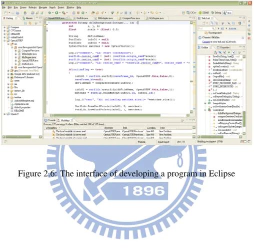
Eclipse
Eclipse is an open source IDE whose projects are responsible for extending develop-ment platform. We use the Android Developdevelop-ment Tools (ADT) plugin for Eclipse for
developing our system. It is easier and faster for us to create and debug Android appli-cations . While developing and debugging the program, we use the DDMS tool to take screenshots, set breakpoints, and view the execution of process from Eclipse. Eclipse also provides an Android code editor to write valid XML files for Android. We can export the project into a signed APK to share to others. Figure 2.6 shows the interface of developing a program in Eclipse.
Chapter 3
Method
3.1
Introduction to navigation method
The following describes the method of overall navigation.
Speech input Speech input provides another way to use mobile phones and is easy-to-use for visually impaired. We integrate speech input and speech recognition on the proposed system via the Android SDK 2.1. As shown in Figure 3.1, it is an example for using speech input to transform a SMS message in Google’s Voice Search application.
Figure 3.1: The example for using speech input (Figure source: [2])
Database construction When human beings are in an unfamiliar place, they memorize compact information about the place. So they can recognize it when they step in next time. Similarly, machines can recognize different places by constructing database with useful information of these places. We have constructed the database of vision-based navigation system, which includes information of a particular region of map. These information con-tain name of stations, a map, GPS locations, adjacency relations, and panoramic images. The more details are described in Section 3.2.
Path planning Since we have constructed the database in the map, the user can input his destination T. Also, the system has known his original position S via GPS sensor, so we can plan a path from T to S. This path is decided by shortest path algorithm. Within the algorithm, S, T, stations and pathways in our map are considered as a ”graph”. The more details are described in Section 3.3.
Point-to-point guidance In point-to-point guidance , our system needs to know the ori-entation and the distance between neighbor positions. That is, the system can guide users what are the distance and the orientation toward the next position. Our system calculates
the distance by GPS sensor on the phone. And our system relies on the compared re-sult with panoramic database to compute the orientation toward the next position. The method of image matching algorithm is described in Section 3.4. Then the system can guide users what are the distance and the orientation toward the next position. Details about the distance and orientation estimation will be described in Section 3.5.
Path monitoring Since the direction is important for visually impaired, we focus on monitoring deviation angle and give alarms to the user if he/she deviates from the planned path. First, we use digital compass sensor on the mobile phone to detect the facing di-rection of the user. Our system sets the degree dlock and the degree drange after starting
the path monitoring process. Our system measures the digital compass degree and checks whether it is out of the range of dlock ± drange. If the user is walking out of the range,
he/she will receive the alarm. At that time, the user needs to turn to the specific direction until the alarm disappears.
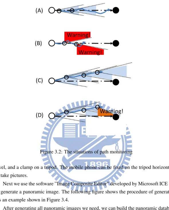
We discuss several situations of the movements of the user which is shown in Fig-ure 3.2. The bigger white and black circles mean the starting position and destination, respectively. The smaller white circle is the specific stations along the path and the light blue triangle region represents the error tolerance of the orientation of the user. The blue crooked arrow represents the movements of the user. First, we do not have to give warn-ings to the user because he/she is walking in the region (Figure 3.2(A)). Second, if the user is walking out of the range, the system gives the user a warning (Figure 3.2(B)). Third, if the user is deviating from the planned path gradually, our system can not detect the situation by digital compass (Figure 3.2(C)). Hence, we also detect the deviation by GPS sensor. That is, if both the deviation of digital compass and GPS are out of the specific range (here, we define ±10 degree for digital compass, ±5 meters for GPS), our system will assume the user deviates from the correct pathway and issue a warning immediately (Figure 3.2(D)).
3.2
Panoramic database construction
It is very important for visually-impaired people to know the exact orientation while walking on a road. If they loss sense of direction, it is easy to deviate from the planned path. In order to provide correct orientation, we want to use the characteristic of panorama. A panorama is a wide-angle view or representation of a physical space. Here, the view angle of a panoramic image is 360 degrees in our system.
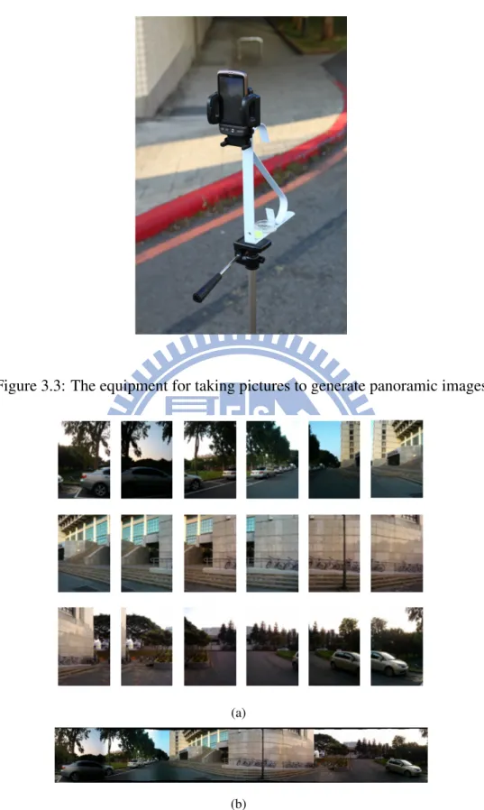
As a pre-processing, we take 18 overlapping pictures for every 20 degrees on a fixed position. The equipment we use is shown in Figure 3.3. We mounted a compass, a spirit
Figure 3.2: The situations of path monitoring
level, and a clamp on a tripod. The mobile phone can be fixed on the tripod horizontally to take pictures.
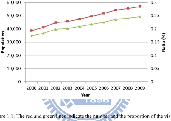
Next we use the software ”Image Composite Editor” developed by Microsoft ICE [10] to generate a panoramic image. The following figure shows the procedure of generating. As an example shown in Figure 3.4.
After generating all panoramic images we need, we can build the panoramic database. We generate each panoramic image on every specific station in our map. And we record the information of index number, name of station, corresponding GPS coordinates, and panoramic image for each station.
3.3
Path planning
We use the definition of graph to define the map. In computer science, a graph is an abstract data structure that is meant to implement the graph concept from mathematics. A graph data structure consists mainly of a finite set of ordered pairs, called edges, of certain entities called nodes or vertices. A graph data structure may also associate to each edge with some edge value, such as weight, cost, capacity, length.
Figure 3.3: The equipment for taking pictures to generate panoramic images
(a)
(b)
Figure 3.4: The example of generating a panoramic image. (a) The overlapping pic-tures which are taken for every 20 degrees horizontally on a fixed position. (b) The generating result of a panoramic image.
It has two kinds of graphs: directed and undirected. A directed graph G is a pair (V, E). The set V is called the vertex set of G, and its elements are vertices or nodes. The set E is called the edge set of G, and its elements are edges.
In an undirected graph G = (V, E), the edge set E consists of unordered pairs of vertices, rather than ordered pairs. That is, an edge is a set u, v, where u, v ∈ V and u 6= v. In an undirected graph, self-loops are forbidden, and so every edge consists of exactly two distinct vertices.
Figure 3.5 is the map of our system. It can be considered as a representation of a
Figure 3.5: The diagram of graph in the map
undirected graph on the vertex set {v1, v2, ..., v14}. Vertices such as v1, v2are represented
by blue circles in the figure, and it can be regard as stations of our system. Edges such as (v1, v2), (v7, v13) are represented by red lines, and it can be regard as pathways of our
system. We also define edge value w(v1, v2) by referencing the distance between edges,
it means that the longer distance implies larger value.
Assume that the user want to start from station v6to station v10. In order to plan a path
which has shortest walking distance, we use the Dijkstra algorithm to decide shortest path in the map. The following is the Dijkstra’s algorithm.
DIJKSTRA(G, W, S)
INITIALIZE-SINGLE-SOURCE(G, S) S ← ∅
Q ← V [G] while Q 6= ∅
do u ← EXT RACT − M IN (Q) S ← S ∪ Q
for each vertex v ∈ Adj[u] do RELAX(u, v, w)
Dijkstra’s algorithm solves the single-source shortest-paths problem on a weighted, directed graph G = (V, E) for the case in which all edge weights are nonnegative. We assume that w(u, v) ≥ 0 for each edge (u, v) ∈ E. With a good implementation, the running time of Dijkstra’s algorithm is lower than that of the Bellman-Ford algorithm.
Dijkstra’s algorithm maintains a set S of vertices whose final shortest-path weights from the source s have already been determined. The algorithm repeatedly selects the vertex u ∈ V − S with the minimum shortest-path estimate, adds u to S, and relaxes all edges leaving u. In the following implementation, we use a min-priority queue Q of vertices, keyed by their d values.
3.4
Image matching
How to find correct point correspondences between two images is important in com-puter vision applications, such as camera calibration, image registration, object recogni-tion, and object tracking. In order to achieve the goal, we use the SURF (Speeded-Up Robust Features) algorithm [4].
Inspired by SIFT descriptor, the SURF algorithm was first presented by Bay et al. [4]. SURF improves the currently used scale and rotation invariant interest point or keypoint detector and descriptor. SURF can be divided into three main steps. First, find interest point in the image. Second, describe every interest point by a feature vector. Finally, match the descriptor vector between different images. The authors of SURF claim that because using several new techniques, the standard version of SURF is several times faster than SIFT and is more robust than SIFT. The followings describe the details of SURF algorithm.
Interest point detection SURF uses a Fast-Hessian Detector to detect interest points or keypoints. In other words, the metric to select the location and the scale points is decided by the determinant of the Hessian. For the calculating step, SURF uses an approximate second order Gaussian derivative using box filters which increases the performance. As a result, the runtime in experiments of the keypoint detector and descriptor detection are 354ms, 391ms, and 1036ms for SURF, SURF-128, and SIFT, respectively.
Interest point description The SURF descriptor is inspired by the SIFT descriptor and they both focus on the spatial distribution of the intensity around the interest point neigh-borhood. It is based on sums of approximated 2D Haar wavelet responses, requiring two steps to construct the SURF descriptor. The first step is finding orientation based on the information around the sub-region near the interest point. Next, a square region is gener-ated and aligned to the selected orientation, and the SURF descriptor is genergener-ated.
Matching In the matching process, SURF keypoints are computed for each image and stored. The approximate distances of the descriptors are computed and sorted using the inner products between unit vectors. A match is accepted if its distance, represented by the ratio of vector angles, is within the distance ratio of 0.95. SURF also uses the sign of Laplacian for fast indexing for matching. The Laplacian can distinguish interest point is bright on dark background or vice versa. Therefore, SURF only compares interest points if they have the same contrast. This feature allows for fast matching.
3.5
Distance and orientation estimation
In this section, we will describe the method we use to estimate distances and orientation in vision-based navigation system.
3.5.1
Distance estimation
In geometry, a coordinate system is a system which uses one or more numbers, or co-ordinates, to uniquely determine the position of a point or other geometric element. A position is composed of datum and format. There are three kinds of datum of coordinate system used in Taiwan: TWD 67 (Taiwan Datum 1967), TWD97 (Taiwan Datum 1997), and WGS84 (World Geodetic System) datum. TWD67 and TWD97 are designed for Tai-wan map, and WGS84 is used in GPS. And the format has two kinds: longitude/latitude, 2-degree transverse Mercator. Because TWD97 is similar to WGS84, and the format of WGS84 is longitude/latitude, we want to transform WGS84 longitude/latitude to TWD97 2-degree transverse Mercator. This can help us to calculate distance and orientations. There is an example shown in table 3.1. We transform WGS84 longitude/latitude to TWD97 datum in meters. Hence, we can estimate the distance between position 1 and 2 is 139 meters.
WGS84 (degree) TWD97 (meter) longitude latitude x y
Position 1 120.99524 24.79488 249518.73 2743056.48 Position 2 120.9962 24.79579 249615.80 2743157.27
Table 3.1: The transforming result for WGS84 and TWD97 datum of positions 1 and 2.
3.5.2
Calculation of turning degree
For the purpose of calculating orientation , we have constructed the panoramic database. Orientation calculation involves four steps:
1. The user takes a forward-facing picture, as the query image. Our system matches the query image with panoramic images in database, and then finds the best match-ing result which has the maximum correspondmatch-ing points.
Figure 3.6: The calculation of the matching center point
2. We assume that the center line of query image is the facing direction of the user, and we know the center point xc in the query image. The next step is to find the
corresponding center point x0c in the panoramic image by using the least squares method. In the following Equation( 3.1) and Equation( 3.2), n is the total number of corresponding points, xi and x0i are the corresponding points in the query image
and the panoramic image respectively (See Figure 3.6). min n X i=1 |(xi− xc) − (x0i− x 0 c)|2 (3.1) x0c= Pn i=1x0n− Pn i=1xn+ n × xc n (3.2)
3. We assume that the degree of panoramic images is 360 degree, and the degree of the leftmost side is defined as Oref, which means the reference of orientation. More
details about the determination of Oref can be found in Section 3.5.3. If we want
to know the facing direction of the user Of acing, we need to calculate the mapping
ratio between x0c and the width of the panoramic image. Then we multiply the ratio by 360. Finally, Of acing is the sum of Oref and the above value (See the
Equation( 3.3)).
Of acing = Oref +
x0c W idthpanorama
× 360 (3.3) 4. We define Dturningas the degree needed to turn to the direction toward next station.
Dturningis the difference between Of acingand Ons, Onsis the direction toward next
station (See Figure 3.7 and Equation( 3.4)). If Onsis bigger than Of acing, the user
might turns to the right, else turns to the left.
Dturning = |Of acing− Ons| (3.4)
Figure 3.7: The calculating process of turning degree.
3.5.3
Orientation calibration
For deciding the reference of panoramic image, we need to calibrate the compass de-gree. We measure GPS longitude and latitude of two positions in a large lawn. As men-tioned previously in Section 3.5.1, the GPS error becomes negligible because of the 139-meter distance between the two position 1 and 2 (Figure 3.8).
Figure 3.8: The two different GPS position 1 and 2.
The degree of the direction between these two positions in GPS coordinate system is 224◦, whereas the compass degree is 236◦. We can obtain that the reference degree of panoramic image is -12 (Figure 3.9).
Chapter 4
4.1
The domain of the panoramic database and testing
data
The result of the corresponding panoramic images in the map is shown in Figure 4.1. The range of the map is in National Chiao Tung University, around Microelectronics and Information Systems Research Building (MISRB), Student Activity Center (SAC), Nano and Microelectronics Research Building (NMRB), and Female Student Dormitory 2(FSD2). Each panoramic image is corresponding to the specific station pointed by the blue arrow pointed to. We record the panoramic image, GPS locations, and adjacency relations for each station in the database.
Figure 4.2: The region of the test data for our experiment.
The range of the testing data of vision-based navigation system is divided into three regions: (A) Microelectronics and Information Systems Research Building, (B) Student Activity Center to Nano and Microelectronics Research Building, and (C) Female Student Dormitory 2 (See Figure 4.2). We took pictures at the positions including stations and non-stations, and about 15-25 pictures for each position. The number of testing data are 193, 178, 75 for region A, B, C, respectively (Figure 4.3, Figure 4.4, and Figure 4.5).
4.2
Results for vision-based navigation system and
sys-tem Performance
4.2.1
Accuracy of image matching
Figure 4.6 shows one snapshot of the interface of vision-based navigation system. The screenshot shows the image matching result between the query image and the database image by SURF algorithm. The query image is the smaller image on the top of the screen,
Figure 4.3: The testing data for region A.
and the matching image in database is the larger image on the bottom of the screen. The red line in query image means the center of the image which can be regarded as the facing direction of the user. The red line in database image can be regarded as the mapping line corresponding to the red line in the query image. The green circle means SURF descriptor, and the yellow line connects each pair of mapping SURF descriptor in the query and the database image.
We have observed that the matching results are usually wrong if the number of match-ing points is less than 2. As shown in Figure 4.7, the above is the query image near MISRB, while the bottom is the panoramic image near Female Dormitory in the database. The red circles are the matching points found in the query image and the panoramic im-age in our system. Hence, we examine imim-age matching results by two principles. First, the number of matching points is greater then or equal to 2. Second, all of the matching points are correct mapping. The image matching results are considered as correct if they achieve the above two principles.
Figure 4.4: The testing data for region B.
image matching is 170. Hence, the image matching accuracy in our system is 69.39% (Figure 4.8). According to Section 4.1, we separate the testing region into three parts: region A, B, and C for different geographical environments. The corresponding accuracy for region A, B, and C are 55.56%, 75.93%, and 80.85%, respectively (Table 4.1). More detail can be found in Section 5.1.
Region Accuracy A 55.56% B 75.93% C 80.85% Total 69.39%
Table 4.1: The accuracy for different region A, B, and C.
4.2.2
The demonstration of vision-Based navigation system
The demonstration of our system are shown in the following figures. As shown in Figure 4.9(a), the user starts the system. In Figure 4.9(b), it is the snapshot of our system.
Figure 4.5: The testing data for region C.
Figure 4.6: The image matching result by SURF algorithm.
The information in the top of screen includes (left to right): name of system, digital compass degree of mobile phone, computing degree of the system, degree of user to turn. The user can consequently capture the environment image as the background on the screen
Figure 4.7: The example of wrong mapping.
Figure 4.8: The number of matching points for each image
of the mobile phone. The system can notify messages to the user through message box and voice.
As shown in Figure 4.10(a), our system asks the request of the user in Mandarin. In Figure 4.10(b), our system starts the speech recognition. If the recognition fails, our system asks the user to speak out the request again. In Figure 4.10(c), the system tells the speech recognition result and shows on the screen meanwhile if the recognition succeeds. As shown in Figure 4.11(a), the user is asked to take a forward-facing picture. In Figure 4.11(b), our system shows the message about image matching by SURF algorithm and orientation calculation. In Figure 4.11(c), our system shows the image matching
(a)
(b)
Figure 4.9: The demonstration of starting system. (a) Initialization. (b) System inter-face.
result and guides the user to turn direction.
As shown in Figure 4.12(a), while the user is walking, our system will track the user’s orientation. If deviating, our system will give beep warnings. In Figure 4.12(b), if the user reaches to a station or destination, our system will give a voice notification and our system shows the remaining distance on the screen every five seconds.
4.3
System performance
The proposed system is implemented in Java language, compiled by Eclipse and ex-ecutable on Android platform. The Android NDK and Google APIs are also applied to
(a)
(b)
(c)
Figure 4.10: The demonstration of speech recognition. (a) Speech ask. (b) Speech recognition. (c) Speech match success.
(a)
(b)
(c)
Figure 4.11: The following demonstration of computing the direction. (a) Taking a forward-facing picture. (b) Image matching processing. (f) Speech guidance to turn direction.
(a)
(b)
Figure 4.12: The following demonstration of the path monitoring and notification. (a) Path monitoring. (b) The notification of station, destination , and the remaining distance.
our system. The system performance is recorded by timer which counts the processing time of matching images on the mobile phone in log files. We construct the proposed vision-based navigation system on the mobile phone with 1 GHz CPU, 576 megabytes ram, and five mega pixel color image. The resolution of each query image is 320 × 240, and 1440 × 244 for the panoramic image in the database. The image matching time for each panoramic image is shown in Table 4.2. The off-line means only counting the image matching time, and the on-line means counting the image matching time and running the system meanwhile.
Matching Time
Off-line 4 ∼ 5 seconds On-line 8 ∼ 10 seconds
Table 4.2: The image matching time for each panoramic image.
4.4
Stability
The most important advantage in our system is robust stability. Figure 4.13 shows the variance of GPS in the same position at different times.
Figure 4.13: The variance of GPS.
Figure 4.14: The variance of using Compass
As shown in Figure 4.14, the variance of using compass. Also we put mobile phone stable as far as possible in our hand while walking, it still has big variance. However,
our system provides more robust and stable results by using computer vision method as shown in Figure 4.15. The red line means the matching line of the facing direction. We compute the standard deviation, and the average, and the variance of computing facing degree between the proposed system and digital compass, as shown in Figure 4.16 and Table 4.3. The standard deviation of the proposed system is lower than digital compass.
Figure 4.16: The matching result for the proposed system.
VBNS Compass STD. 1.98 4.08 Average 44.19 39.09
Chapter 5
Conclusions
5.1
Discussions
Issues for matching accuracy As mentioned previously in Section 4.2.1, the accuracy in region A, B, and C are: A < B < C. We observe that the geographical environment in region A is more complicated than B and C. The pathway in region A has two intersection, only near one building (MISRB), illumination change, and many non-static region such as cars, moving people and trees (Figure 5.1).
The above reasons cause the difficulties of recognition. The region B is a straight road, and has more buildings along the path. Hence, it is easier to match the database. The reason for high accuracy of region C is the distinctiveness of FSD2, therefore it has the highest accuracy.
Figure 5.1: The example of non-static region and illumination change. (a)Cars (b)Moving people and cars (c)Trees (d)Illumination change.
Causes of inaccuracy In our system, we have previously established in the panoramic database, and the starting position and destination of the user must near stations in the panoramic database. Causes of inaccuracy: GPS, calibration, and human factors.
5.2
Conclusions
In this work, we have proposed a vision-based navigation system for visually impaired people using computer vision method. In initialization, we construct the database which includes GPS information, map, and panoramic images. Then our system provides a friendly user interface to support speech input and output. Our system first record the GPS information of the user. According to the destination of user, we plan a shortest path. The most important need for visually impaired people is the information of orientation. We use computer vision methods, SURF algorithm and least square method, to calculate the orientation which the user needs to turn. Besides, we provides the distance information for the user to know how far to reach each station and destination. On path monitoring, we give issue an alarm if the user’s orientation is over 10 degrees. The user needs to turn back to the correct orientation until the alarm silences. Finally, our system will notify the user when they arrive each station or the destination. The advantage of our system is stable and robust. Although the accuracy is not high, we provide the chances to take a picture again when the user needs to calculate his orientation. In the future, we want to expend the region of the database and to improve the matching accuracy. We hope our system can improve the daily lives for visually impaired people.
Bibliography
[1] The architecture of androidar. Website. http://developer.android.com/ guide/basics/what-is-android.html.
[2] Speech input. Website. http://developer.android.com/resources/ articles/speech-input.html.
[3] H. H. Alan L. Liu, H. Kautz, G. Borriello, P. A. Brown, M. Harniss, and K. Johnson. Indoor wayfinding: Developing a functional interface for individuals with cognitive impairments. In Proceedings of Computers Accessibility, ASSETS, pages 95–102, 2006. .
[4] H. Bay, A. Ess, T. Tuytelaars, and L. V. Gool. Surf: Speeded up robust features. In Computer Vision and Image Understanding (CVIU), volume 110, pages 346–359, 2008.
[5] M. G. Dodson AH, Moore T. A navigation system for the blind pedestrian. In GNSS 99, page 513–518, 1999. .
[6] R. G. Golledge, R. L. Klatzky, J. M. Loomis, J. Speigle, and J. Tietz. A geographical information system for a gps based personal guidance system. In Int J Geograph Inform Sci, page 727–749, 1998. .
[7] B. JA. A review of mobility aids and means of assessment. In In: Warren DH, Strelow ER (eds) Electronic spatial sensing for the blind. Martinus Nijho, page 13–27, 1985. .
[8] K. L. Air sonar with acoustical display of spatial information. In Busnel RG, Fish JF (eds) Animal sonar system. Plenum, New York, page 769–816, 1980. .
[9] S. H. Lisa Ran and S. Moore. Drishti: An integrated indoor/outdoor blind naviga-tion system and service. In Proceeings of the Second IEEE Annual Conference on Pervasive Compuing and Communications (PerCom.04), pages 23–30, 2004. .
[10] Microsoft. Image composite editor. Website. http://research. microsoft.com/en-us/um/redmond/groups/ivm/ICE/.
[11] E. E. Sabelman, C. G. Burgar, G. E. Curtis, G. Goodrich, D. L. Jaffe, J. L. McKinley, M. V. der Loos, and L. G. Apple. Personal navigation and wayfinding for individuals with a range of disabilities. In Project report: Device development and evaluation, 1994. http://guide.stanford.edu/Publications/dev3.html. [12] T. Strothotte, S. Fritz, R. Michel, A. Raab, H. Petrie, V. Johnson, L. Reichert, and
A. Schalt. Development of dialogue systems for the mobility aid for blind people: initial design and usability testing. In ASSETS ’96, page 139–144, 1996. .
![Figure 1.3: Drishti: outdoor mobile user(left) and indoor mobile user(right). (Figure source: [9])](https://thumb-ap.123doks.com/thumbv2/9libinfo/8129993.166206/19.892.258.634.812.1085/figure-drishti-outdoor-mobile-indoor-mobile-figure-source.webp)
![Figure 1.4: Indoor Wayfinding.(Figure source: [3])](https://thumb-ap.123doks.com/thumbv2/9libinfo/8129993.166206/20.892.152.708.223.758/figure-indoor-wayfinding-figure-source.webp)
![Figure 2.4: The Architecture of Android. (Figure source: [1])](https://thumb-ap.123doks.com/thumbv2/9libinfo/8129993.166206/27.892.181.712.660.1042/figure-architecture-android-figure-source.webp)
![Figure 3.1: The example for using speech input (Figure source: [2])](https://thumb-ap.123doks.com/thumbv2/9libinfo/8129993.166206/32.892.172.713.359.728/figure-example-using-speech-input-figure-source.webp)