Secondary electron emission characteristics of oxide electrodes in flat electron
emission lamp
Chang-Lin Chiang, , Hui-Kai Zeng, Chia-Hung Li, Jung-Yu Li, , Shih-Pu Chen, Yi-Ping Lin, Tai-Chiung Hsieh, and Jenh-Yih Juang,
Citation: AIP Advances 6, 015317 (2016); doi: 10.1063/1.4941317 View online: http://dx.doi.org/10.1063/1.4941317
View Table of Contents: http://aip.scitation.org/toc/adv/6/1 Published by the American Institute of Physics
Secondary electron emission characteristics of oxide
electrodes in flat electron emission lamp
Chang-Lin Chiang,1,2,aHui-Kai Zeng,3Chia-Hung Li,1,2Jung-Yu Li,1,b
Shih-Pu Chen,1Yi-Ping Lin,1Tai-Chiung Hsieh,2and Jenh-Yih Juang2,c 1Green Energy and Environment Research Laboratories, Industrial Technology Research
Institute, 195, Sec. 4, Chung Hsing Road, Chutung 310, Taiwan
2Department of Electrophysics, National Chiao Tung University, 1001 Ta Hsueh Road,
Hsinchu 300, Taiwan
3Department of Electronic Engineering, Chung Yuan Christian University,
200 Chung Pei Road, Chung Li 320, Taiwan
(Received 29 October 2015; accepted 18 January 2016; published online 29 January 2016)
The present study concerns with the secondary electron emission coefficient, γ, of the cathode materials used in the newly developed flat electron emission lamp (FEEL) devices, which essentially integrates the concept of using cathode for fluorescent lamp and anode for cathode ray tube (CRT) to obtain uniform planar lighting. Three different cathode materials, namely fluorine-doped tin oxide (FTO), aluminum oxide coated FTO (Al2O3/FTO) and magnesium oxide coated FTO (MgO/FTO) were
pre-pared to investigate how the variations of γ and working gases influence the perfor-mance of FEEL devices, especially in lowering the breakdown voltage and pressure of the working gases. The results indicate that the MgO/FTO bilayer cathode exhib-ited a relatively larger effective secondary electron emission coefficient, resulting in significant reduction of breakdown voltage to about 3kV and allowing the device to be operated at the lower pressure to generate the higher lighting efficiency. C 2016
Au-thor(s). All article content, except where otherwise noted, is licensed under a Creative Commons Attribution (CC BY) license (http://creativecommons.org/licenses/by/4.0/). [http://dx.doi.org/10.1063/1.4941317]
I. INTRODUCTION
Owing to the increasing concerns of environmental sustainability globally, obtaining the mercury-free lighting has been one of the hotly pursued issues worldwide. To this respect, a recently devel-oped flat electron emission lamp (FEEL) represents a potential technology capable of providing a mercury-free planar light source with high-uniformity.1The basic concept of FEEL is to utilize the
energetic electrons emitted from the cathode to excite the cathodoluminescent phosphors coated on the anode and give rise to the desired luminance. However, unlike the traditional field emission configuration frequently used in display technologies,2–5FEEL devices utilize the gas glow discharge to generate secondary electrons and hence can overcome the drawbacks of point-like radiations resulting from field emission schemes for a much more uniform planar lighting.6,7Previous studies1,6,7
indicated that, in order to obtain effective gas ionization and secondary electron emissions, FEEL devices were largely operated at the left hand side of the minimum of the Paschen curve, which describes the relation between the breakdown voltage for glow discharge and the parameter pd. Where p and d denote the working pressure of the discharged gas and the distance between the cathode and anode of the device, respectively. In general, the left hand-side of the Paschen curve represents an environment very sensitive to gas pressure with relatively higher breakdown voltage and kinetic energy and, hence, is relatively seldom explored in more commercialized lighting devices
aElectronic mail:[email protected] bElectronic mail:[email protected] cElectronic mail:[email protected]
015317-2 Chiang et al. AIP Advances 6, 015317 (2016)
such as cold cathode fluorescent lamps (CCFLs),2 plasma display panel (PDPs),3 field emission
displays (FEDs)4as well as gas discharge lamps (GDLs)5Therefore, in order to gain more insights
on the unique physical properties associated with the harsh working environments and to improve the performance of FEEL devices, such as to lower the operation voltage and to enhance the luminance, more investigations are necessary. In particular, since the gas discharge prevailing in the present FEEL devices is mainly dominated by two factors, namely the operation pressure of the working gas and the cathode material used in the device. Therefore, how to obtain enough numbers and kinetic energy of the electrons with reduced operation voltage has become one of the critical issues for improving the lighting efficiency.
Previously, fluorine-doped tin oxide (FTO) had been used as the cathode electrode of the FEEL devices due to its transparent and conductive characteristics. Nevertheless, the requirement of rela-tively higher discharge voltage and shorter lifetime, presumably resulting from lower secondary electron emission coefficient ion-bombardment damage, have hindered the realization of the FEEL devices for practical use. Hence, developing protective layers capable of lowering the required discharge voltage and providing more robust endurance to ion-bombardment is necessary. It has been established that, in addition to the gas species and the operating pressure, the secondary electron yield of cathode is closely related to the discharge voltage.8–10For instance, the breakdown
voltage in PDP was found to reduce significantly if the ion-induced secondary electron emission of the cathode was increased.11,12Thus, choosing materials with higher secondary electron emission coefficient should be beneficial to lower the discharge voltage and hence reduce the device power consumption. Moreover, previous studies had indicated that using MgO as the cathode of ac PDPs not only gave rise to advantages of low firing temperature and good durability,13,14but also could
serve as a stable protective layer overlying on the glass dielectric electrode.15,16On the other hand,
due to its high hardness, high abrasive resistance, good thermal and chemical stability, and high optical transparency Al2O3 has become a choice of packaging material for electronics and optics
industry.17,18 It is thus a potential cathode material for the present FEEL devices. In this study, we investigated the effects of cathode material on the luminescence of FEEL device by systemati-cally comparing the influences of using three different cathode materials, namely FTO, MgO/FTO, Al2O3/FTO, on the device performances, while keeping the same phosphors-coated FTO as the
anode. In particular, the effects on breakdown voltage and associated gas discharge characteristics will be addressed.
II. EXPERIMENTALS
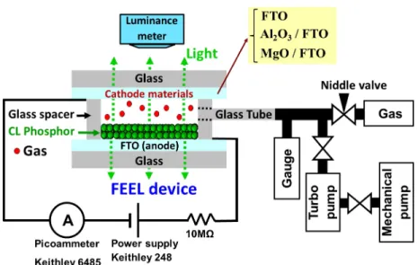
The FEEL devices investigated in this study were constructed with two FTO coated glasses separated by a 10mm spacing, as depicted schematically in Fig.1. On the anode surface, a defined area of 30*30 mm2was spin-coated with the P22-GN4 phosphors (Nichia, Ltd)/polyethylene oxide
(PEO) slurry followed by a heat treatment at 450◦C for 1 h. On the other hand, three different
materials were used for the cathode electrodes, namely the pristine FTO-coated glass substrate, the bilayer Al2O3/FTO and MgO/FTO coated glass substrates. The MgO layers were deposited by
RF-sputtering operating at a power of 2000 W with mixed gases of Ar+ O2. A metallic Mg target was
used and the flow rate of Ar and O2were 150 sccm and 4 sccm, respectively. The Al2O3layer was
deposited by DC-sputtering using an Al metal target. The input power was 1500 W and the flow rate of Ar and O2were 150 sccm and 30 sccm, respectively. The thickness of both MgO and Al2O3was
about 50 nm each. A glass tube was connected to the FEEL device and vacuum system for evacuat-ing and adjustevacuat-ing nitrogen pressure in the space of the devices. The electrode and spacer were sealed by glass glue with infused 99.999%-pure nitrogen, argon, or neon as the working gas. The pressure of the working gases was monitored by a vacuum gauge attached to pumping system and was kept at a set constant value during the entire course of measurement. The pressure of the working gas inside the FEEL devices was varied between 0.04 torr and 40 torr by adjusting the gas flow rate.
The two electrodes of the FEEL device were connected to a DC voltage power supply (Keith-ley 248) and a picoammeter (Keith(Keith-ley 6485) to trigger the discharge and analyze the associated current-voltage characteristics and the Paschen curves. A 10 MΩ resistor was connected in series with FEEL device to limit and stabilize the discharge currents. The luminance meter, multi-function
FIG. 1. The schematics of the FEEL device structure and the experimental setup for measuring the lighting and discharge properties.
color analyzer (Ruyico Tech.), was situated at the top of the transparent cathode for capturing the luminescence properties of the devices.
Kruithof19pointed out that the values of secondary electron emission coefficient can be very sensitive to the surface conditions of the electrodes. Therefore, in all experiments plasma treatment was carried to clean the electrode surface prior to discharge measurements. The pre-treatment was carried out by nitrogen plasma at 0.15 torr with an operating voltage of 3kV for 10 min.
III. RESULTS AND DISCUSSIONS
Figure 2 shows the current-voltage characteristics (IVCs) of FEEL devices with the three different cathode materials, namely FTO, MgO/FTO and Al2O3/FTO. It is noted that, except for
the cathode material, all the conditions for the FEEL devices were the same and the pressure of the operating gas (nitrogen in this case) was kept at a certain constant value (e.g. 0.11 torr) during the entire course of measurement. In general, a typical IVC of the discharge type device would contain the common features corresponding to the following physical processes, namely background ioni-zation, electron multiplication leading to the breakdown voltage of the Townsend discharge, voltage drop, the normal discharge, the abnormal discharge.20,21 Starting from the regime of background ionization, the current is arisen from ionization of gas molecules induced by ultraviolet, cosmic radiation and radioactivity, thus the initial current is very small (∼10−9A). As the electric field is increased, although the number of ions and electrons are both increased, the increased effective recombination coefficient also promotes the neutralization between the two. Therefore, the total number of charged particles does not increase significantly in this regime and the current remains relatively small. With further increase in applied voltage, the multiplication process becomes more and more frequent and the electron emission from the cathode starts to engage. In this stage, in addition to an avalanche-like increase in current (from nA to µA), Crowe22 pointed out that the
slope of the IVC also appears to be negative at the breakdown. It is apparent from Fig.2that the breakdown voltage (Vb) is very much dependent on the cathode material used. Namely Vbfor FTO,
Al2O3/FTO, and MgO/FTO cathodes are 4330V, 1520V, and 920V, respectively.
The apparent negative resistance appearing immediately after breakdown is a classical char-acteristic of dc gas discharge. The electrons giving rise to the avalanche-like current increase are mainly from two sources: gas ionization described by the Townsend’s first ionization coefficient and electrons emitted from cathode material due to the bombardment of energetic ions represented
015317-4 Chiang et al. AIP Advances 6, 015317 (2016)
FIG. 2. The current-voltage characteristics of FEEL devices at the operation of 0.11 torr nitrogen for FTO, Al2O3/FTO, and
MgO/FTO thin film as the cathode electrodes.
by the secondary electron emission coefficient, γ. Both α and γ are playing decisive roles for determining the breakdown voltage of gas discharge through the Paschen expression:20,23,24
Vb=
C pd
ln[Apd/ ln(1 + 1/γ)]. (1)
Where A and C represent the phenomenological constants closely related to the Townsend’s first ionization coefficient α, γ represents the secondary electron emission coefficient of cathode, pis the gas pressure inside the discharge space, and d is the distance between the two electrodes. Thus, by analyzing the relation between Vb and pd, also known as the Paschen curve, one can
investigate how the gas species and cathode materials affect the performance of the device in a more quantitative manner.
Figure3shows the Paschen curves for FEEL devices operating with the same gas but different cathode materials (Fig. 3(a)) and that operating with different gases but with the same cathode material (Fig. 3(b)). In order to obtain a more comprehensive picture, the gas pressure has been covered nearly three orders of magnitude (pd= 0.10-40 torr-cm). It is apparent that Vbis much more
sensitive to the cathode material on the left hand side of the Paschen curve minimum, suggesting
FIG. 3. (a) Breakdown voltages measurement at three different cathode materials (FTO, Al2O3/FTO, and MgO/FTO). Each
cathode material is compared at the same pressure * distance product. (b) Breakdown voltages measurement at three different working gases (nitrogen, argon, and neon). Each working gas is compared at the same pressure*distance product.
that, at lower gas pressures, the electron emission from the cathode may become the dominant process for the glow discharge behavior. In particular, the incorporation of a 50 nm-thick oxide layer on the cathode appears to have significantly lowered the breakdown voltage with MgO being more effective than Al2O3. It is also interesting to observe that beyond the Paschen curve minimum
to-ward the higher pd values Vbbehaves essentially the same for all three different cathodes, indicating
that the electron emission from the cathode is less influential to glow discharge prevailing in this regime. On the other hand, with different working gases, namely N2, Ar, and Ne, the breakdown
behavior becomes more sensitive to the gas species in the higher pd regime (Fig. 3(b)). As can be seen from Fig. 3(b), the slope of the Paschen curves on the right hand side of the minimum appears to be much smaller than that on the low pd regime. In particular, for Ar and Ne gases, the breakdown voltage remains at a relatively low value over a wide range of pressures, presumably due to the differences in the first ionization coefficient (α). Indeed, as indicated by Roth,20the
phenome-nological constants A and C in the expression representing the Townsend first ionization coefficient for N2, Ar, and Ne gases are 1060 ion-pairs/m-torr and 34200 V/m-torr, 1200 ion-pairs/m-torr and
20000 V/m-torr, and 400 ion-pairs/m-torr and 10000 V/m-torr, respectively.
In order to obtain a more quantitative measure of the secondary electron emission coefficients for the cathodes used in this study, the data shown in Fig.3(a)were analyzed by using expression (1). By differentiating the Paschen’s expression with respect to pd, the slope of Paschen curve at certain pd value is given by:
d(Vb)
d(pd) =
c[ln(ln(1+1/γ)Apd ) − 1]
[ln(ln(1+1/γ)Apd )]2
. (2)
Right at the minimum of the Paschen curve, where the derivative of expression (2) should be zero and following relations can be obtained:20,23,24
ln[ A(pd)min . ln(1 + 1/γ)] = 1. (3) and (pd)min .= e Aln(1 + 1 γ ). (4)
By plugging in (pd)min≈ 1.1 torr-cm for all three cases, the obtained γ values for FTO,
Al2O3/FTO, and MgO/FTO cathodes are 0.0067, 0.0088, and 0.0114, respectively. It has been show
that electron yield, both by ion- and photo-induced processes is strongly influenced by the band gap and electron affinity of the material.25,26 While the former is important to breakdown voltage, the
latter is more relevant to the secondary electron emission. The materials that have lower electron affinities are potentially having a higher electron emission yield. The electron affinity for MgO and Al2O3are 0.8 eV and 1.0 eV, respectively.26 It is apparent that our results are consistent with this
general trend. These values, although can explain the tendency of reducing the breakdown voltage by the incorporation of the Al2O3and MgO layers on the surface of the cathode, nevertheless, are
somewhat too small to account for substantial reduction of breakdown voltage in the low pressure regime. In particular, comparing to the values of 0.040∼0.099 reported for MgO by focused ion beam system with Ne+ions of ∼1010ions/cm3,27the values are about a factor of 4∼10 smaller. The
differences may have resulted from the measuring conditions used and/or the ion species that were used to induce the secondary electrons.15Moreover, the values were obtained based on one single
condition and, thus, may not reflect the actual situations over the entire range of operating pressures. Alternatively, one can also use expression (1) to calculate the coefficient γ at every operation condition directly. Figure 4 displays the results for a total of 15 FEEL devices operated with ni-trogen gas of various pressures. Apparently, the value of γ is indeed very much dependent on the parameter E/p, where E and p are the effective field and pressure inside the glow discharge space, respectively. It is also interesting to observe that for each set of samples the data are more or less falling into the same curve, indicating that the characteristics are genuine and are reflecting the response of cathode to the incoming ions. We note that in the calculation the values of constants
015317-6 Chiang et al. AIP Advances 6, 015317 (2016)
FIG. 4. Effective secondary electron emission coefficient (γeff.) of FTO, Al2O3/FTO, and MgO/FTO thin film as cathode
electrodes for nitrogen.
Aand C being used are 1060 ion-pairs/m-torr and 34200 V/m-torr, respectively. These values are valid only when the parameter E/p is within the range of C/25 E/p 5 3C,20 as indicated by the shaded area shown in Fig. 4. Nevertheless, the results, at least for MgO, are in much better agreement with the abovementioned values obtained from focus ion beam measurements.27It is also worth mentioning that the results displayed on the lower E/p values (i.e. left to the minimum) are almost the same for all three different cathode materials, which apparently is not reflecting the real situations, because it is in the gas ionization dominant regime.
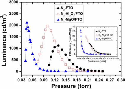
Next we will discuss how the “effective” γ values affect the performance of the FEEL devices. Previously, it has been demonstrated that in order to obtain adequate electron kinetic energy to
FIG. 5. The lighting characteristics and efficiency of FEEL device with FTO, Al2O3/FTO, and MgO/FTO thin film as cathode
excite the phosphors on the anode, the FEEL devices were most operating in the pd range of 0.09-0.2 torr-cm with a typical operation voltage of ∼1000 V.1,6,7Figure5shows the luminance as
a function of operating gas pressure for FEEL devices with the three different cathode materials in the pressure range of 0.04-0.25 torr. Significant lighting luminance enhancement from ∼880 cd/m2
for FEEL with the FTO cathode to over ∼2000 cd/m2for that with MgO/FTO cathode is evident.
The efficiency as a function of pressure is also displayed in the inset of Fig. 5 for comparison. The lighting efficiency is around 10-11 Lm/W for device with FTO as cathode electrode, which can be enhanced up to 23-27 Lm/W by coating a layer of MgO on FTO. Based on Fig.4, the γ values at E/p ∼ 10000 V/torr-cm for FTO, Al2O3/FTO, and MgO/FTO are 0.193, 0.263, and 0.396,
respectively. It is apparent that the larger γ values can effectively reduce both the working gas pressure, which in turn reduces the collisions between the electrons and gas ions and preserves the kinetic energy of electrons necessitated for exciting phosphors at the anode. It is also noted that FEEL devices with both MgO/FTO and Al2O3/FTO as cathode materials exhibited an enhancement
in device lifetime by about 4 times, presumably due to the reduction of breakdown voltages.
IV. CONCLUSIONS
In conclusion, by systematically analyzing the current-voltage characteristics and associated Paschen curves of a series of flat electron emission lamp (FEEL) devices with three different cathode materials (MgO/FTO, Al2O3/FTO, FTO), an experimental method for determining the
secondary electron emission coefficient (γ) as a function of reduced electric filed was demonstrated. It is observed that, while using the Paschen curve minimum to calculate γ is more convenient, the values obtained were about an order of magnitude smaller than those reported by using standard focus ion beam measurement systems. On the other hand, by calculating the each point of the Paschen curve gave a much better account for the effective γ values for real operation conditions. Our results show that, under the typical operation conditions of FEEL devices, the γ values for FTO, Al2O3/FTO, and MgO/FTO are 0.193, 0.263, and 0.396, respectively. The larger γ value obtained
for MgO consistently accounts for both the significant reduction in breakdown voltage and marked enhancement in lighting efficacy and device lifetime.
ACKNOWLEDGMENTS
The authors would like to acknowledge the support from the Energy Fund of Ministry of Eco-nomics Affairs, Taiwan. The authors would also like to acknowledge the support from the Energy Foundation. JYJ is supported in part by Ministry of Science and Technology, Taiwan under grant: MOST 103-2112-M009-015-MY3 and MOE ATU program operated at NCTU.
1J. Y. Li, S. P. Chen, C. H. Li, Y. P. Lin, Y. I. Chou, M. C. Liu, P. H. Wang, H. K. Zeng, T. C. Hsieh, and J. Y. Juang,Appl.
Phys. Lett.94, 091501 (2008).
2Y. C. Choi, J. W. Lee, S. K. Lee, M. S. Kang, C. S. Lee, K. W. Jung, J. H. Lim, J. W. Moon, M. I. Hwang, I. H. Kim, Y. H.
Kim, B. G. Lee, H. R. Seon, S. J. Lee, J. H. Park, Y. C. Kim, and H. S. Kim,Nanotechnology19, 235306 (2008).
3L. F. Weber,IEEE Trans. Plasma Sci.34, 268 (2006).
4W. B. Choi, D. S. Chung, J. H. Kang, H. Y. Kim, Y. W. Jin, I. T. Han, Y. H. Lee, J. E. Jung, N. S. Lee, G. S. Park, and J. M.
Kim,Appl. Phys. Lett.94, 3129 (1999).
5Y. Yoshida, A. Ishizuka, and H. Makishima,Mater. Chem. Phys.40, 267 (1995).
6J. Y. Li, M. C. Liu, Y. P. Lin, S. P. Chen, T. C. Hsieh, P. H. Wang, C. L. Chiang, M. S. Jeng, L. L. Lee, H. K. Zeng, and J.
Y. Juang, in Cathodoluminescence, edited by Naoki Yamamoto (InTech, Croatia, 2012), p. 305.
7C. H. Li, M. C. Liu, C. L. Chiang, J. Y. Li, S. P. Chen, T. C. Hsieh, Y. I. Chou, Y. P. Lin, P. H. Wang, M. S. Chun, H. K.
Zeng, and J. Y. Juang,Opt. Express19, A51 (2011).
8O. Sahni and C. Lanza,J. Appl. Phys.47, 1337 (1976).
9M. Ishimoto, S. Hidaka, K. Betsui, and T. Shinoda, in SID international symposium digest of technical papers (Society
for Information Display, San Jose, 1999), pp. 552-555.
10H. S. Uhm, E. H. Choi, and J. Y. Lim,Appl. Phys. Lett.80, 737 (2002).
11H. Uchiike, K. Miura, N. Nakayama, T. Shinoda, and Y. Fukushima,IEEE Trans. Electron Dev.23, 1211 (1976). 12H. S. Uhm, E. H. Choi, and G. S. Cho,Appl. Phys. Lett.78, 592 (2001).
13T. Urade, T. Iemori, M. Osawa, N. Nakayama, and I. Morita,IEEE Trans. Electron Dev.23, 313 (1976). 14N. J. Chou and O. Sahni,IEEE Trans. Electron Dev.25, 60 (1978).
015317-8 Chiang et al. AIP Advances 6, 015317 (2016)
15J. Y. Lim, J. S. Oh, B. D. Ko, J. W. Cho, S. O. Kang, and G. Cho,J. Appl. Phys.94, 764 (2003). 16B. W. Byrum, Jr.,IEEE Trans. Electron Dev.22, 685 (1975).
17F. Fietzke, K. Goedicke, and W. Hempel,Surf. Coatings Technol.86-87, 657 (1996).
18R. Cueff, G. Baud, M. Benmalek, J. P. Besse, J. R. Butruille, H. M. Dunlop, and M. Jacquet,Thin Solid Films270, 230
(1995).
19A. A. Kruithof,Physica (Amsterdam)7, 519 (1940).
20J. R. Roth, Industrial Plasma Engineering-Volume1, Principle (Institute of Physics Publishing, London, 1995), p. 275. 21A. von Engel, Ionized Gases (Oxford University Press, New York, 1965), p. 222.
22R. W. Crowe, J. K. Bragg, and V. G. Thomas,Phys. Rev.96, 10 (1954). 23A. von Engel, Ionized Gases (Oxford University Press, New York, 1965), p. 193.
24M. M. Pejovic, G. S. Ristic, and J. P. Karamarkovic,J. Phys. D: Appl. Phys.35, R91 (2002).
25T. J. Vink, A. R. Balkenende, R. G. F. A. Verbeek, H. A. M. van Hal, and S. T. de Zwart,Appl. Phys. Lett.80, 2216 (2002). 26R. C. Alig and S. Bloom,J. Appl. Phys.49, 3476 (1978).