1
國立交通大學
材料科學與工程研究所
博士論文
沉積在金屬氧化物載體上之鉑金屬奈米粒對甲醇氧化反
應之電催化特性研究
Electrocatalytic activity of Pt nanoparticles supported on
metal oxides toward methanol oxidation
研 究 生:陳重守
指導教授:潘扶民 教授
2
沉積在金屬氧化物載體上之鉑金屬奈米粒對甲醇氧化反應之電
催化特性研究
Electrocatalytic activity of Pt nanoparticles supported on metal
oxides toward methanol oxidation
研 究 生:陳重守 Student: Chung-Shou Chen 指導教授:潘扶民 教授 Advisor: Fu-Ming Pan
國立交通大學
材料科學與工程研究所
博士論文
A Thesis
Submitted to Department of Materials Science and Engineering
College of Engineering
National Chiao Tung University
In partial Fulfillment of the Requirements
for the Degree of Doctor of Philosophy
In Materials Science and Engineering
July 2011
Hsinchu, Taiwan, Republic of China
I
沉積在金屬氧化物載體上之鉑金屬奈米粒對甲醇氧化反應之電催化特性
研究
研究生:陳重守 指導教授:潘扶民 教授 國立交通大學 材料科學與工程學系博士班摘要
本研究製備多孔性二氧化鈦、氧化鈀奈米薄片及類卡斯特形貌之氧化鎳薄膜做為 鉑金屬奈米粒之載體,並探討鉑奈米粒對甲醇氧化反應之電催化特性,此三種氧化物 薄膜具有高表面積可提供較多的表面沉積鉑奈米粒子,進而使鉑催化劑有較高的電化 學活性表面積(ESA),循環伏安及一氧化碳脫附實驗指出此三種氧化物載體有效提升 鉑奈米粒對甲醇氧化反應之催化活性及抗一氧化碳毒化的能力。 我們利用水熱法製備多孔性二氧化鈦作為鉑金屬奈米粒載體探討甲醇氧化反應之 電催化研究,5-7 奈米大小的鉑金屬粒以脈衝電鍍法均勻地電鍍在經由 600o C 真空退 火之多孔性二氧化鈦載體,鉑/二氧化鈦電極在循環伏安及一氧化碳脫附實驗中展現對 甲醇氧化優異的電催化特性及抗一氧化碳毒化能力,我們歸因此優異的電催化活性為 鉑奈米粒與氧化物之間的協同效應所造成,鉑金屬與二氧化鈦載體間電荷交互作用將 改變鉑表面的一氧化碳吸附性質,並經由雙官能基機制進而加速吸附在鉑表面的一氧 化碳之氧化,並增加鉑催化甲醇氧化的能力。 氧化鈀奈米薄片經由反應性濺鍍沉積在碳布上,接著以脈衝電鍍法沉積鉑奈米粒 製備鉑/氧化鈀電極,我們發現在酸性環境中之循環伏安量測,氧化鈀奈米薄片之電化 學行為與金屬鈀相似,這是氧化鈀表面在循環伏安量測過程中還原成金屬鈀薄膜之故, 因此金屬鈀/氧化鈀的氧化還原行為將影響氧化鈀在循環伏安量測中對甲醇氧化的電II 催化特性,我們提出一組化學反應機制流程圖用以解釋氧化鈀在酸性溶液中對甲醇氧 化反應之現象。此外因為鈀金屬容易溶解於酸性電解液中,因此氧化鈀之奈米薄片形 貌在酸性溶液中將會嚴重崩解,但我們發現,將鉑奈米粒沉積於氧化鈀表面將有效減 緩氧化鈀之奈米薄片形貌崩解於酸性電解液中。 粗糙表面的鎳薄膜擁有類卡斯特之形貌,可提供高表面積經由脈衝電鍍法讓鉑奈 米粒沉積,在鹼性環境下,鉑/鎳電極在循環伏安中在展現優異的甲醇氧化反應及抗一 氧化碳毒化特性,循環伏安過程中氧化鎳載體可在表面形成氫氧化鎳,這將有助於鉑 金屬經由雙官能基機制提升抗一氧化碳的能力,Langmuir-Hishelwood 及 Eley-Rideal 機制分別用來解釋氫氧基吸附於氧化鎳載體及氫氧離子在鹼性溶液中如何增加鉑金屬 抗毒化能力,XPS 分析指出鉑奈米粒與鎳載體間的電荷轉移,此電荷交互作用將改變 鉑表面的一氧化碳吸附性質,有助於一氧化碳被氫氧基氧化之反應,此氫氧基由鎳載 體或鹼性電解液中獲得並吸附在鉑奈米粒周圍。 鉑/二氧化鈦,鉑/氧化鈀,鉑/鎳此三種電極有優異的甲醇氧化之電催化特性,我 們將此優異之電催化效率歸因於優異的一氧化碳容忍度及高電化學活性表面積,發生 在鉑奈米粒與三種金屬氧化物之間的電荷交互作用與雙官能基機制發揮了協同效應, 顯著提升鉑奈米粒抗一氧化碳毒化能力,進而增進對甲醇氧化反應之電催化活性。 關鍵詞: 直接甲醇燃料電池;甲醇氧化反應;抗一氧化碳毒化;鉑奈米粒;雙官能基 機制;電荷效應;孔洞性二氧化鈦;氧化鈀;鎳
III
Electrocatalytic activity of Pt nanoparticles supported on metal oxides reactions toward methanol oxidation
Student: Chung-Shou Chen Adviser: Fu-Ming Pan
Departement of Materials Science and Engineering National Chiao Tung University
Abstract
Pt nanoparticles were prepared on nanostructured metal oxides as the electrocatalyst for methanol oxidation reaction (MOR) in this study. Pt nanoparticles were pulse-electrodeposited on the metal oxides, which included nanoporous TiO2 thin film, PdO
nanoflake thin film and karst-like NiO thin film. Because of the large loading area on these support and the well-dispersed Pt nanoparticles, these Pt-metal oxide electrodes had a large electrochemical active surface area (ESA). Cyclic voltammetry (CV) and CO stripping measurements showed that the Pt/TiO2, Pt/PdO and Pt/karst-Ni electrode had a
high electrocatalytic activity toward methanol oxidation and an excellent CO tolerance compared with the blanket Pt electrode.
Porous TiO2 thin films were prepared on the Si substrate by hydrothermal method, and
used as the Pt electrocatalyst support for methanol oxidation study. Well-dispersed Pt nanoparticles with a size of 5-7 nm were pulse-electrodepotied on the porous TiO2 support,
which was mainly composed of the anatase phase after an annealing at 600oC in vacuum. Cyclic voltammetry (CV) and CO stripping measurements showed that the Pt/TiO2
electrode had a high electrocatalytic activity toward methanol oxidation and an excellent CO tolerance. The excellent electrocatalytic performance of the electrode is ascribed to the synergistic effect of Pt nanoparticles and the porous TiO2 support on CO oxidation.
IV
The strong electronic interaction between Pt and the TiO2 support may modify CO
chemisorption properties on Pt nanoparticles, thereby facilitating CO oxidation on Pt nanoparticles via the bi-functional mechanism and thus improving the electrocatalytic activity of the Pt catalyst toward methanol oxidation.
PdO nanoflake thin films on carbon cloths were prepared by reactive sputtering deposition, and pulse-electrodeposited Pt nanoparticles on the PdO thin films. In acidic electrolytes, the PdO nanoflake thin film has a cyclic voltamperometric (CV) behavior similar to a metallic Pd electrode because of the formation of a metallic Pd surface layer on the PdO thin film under the CV experimental condition. The methanol oxidation reaction (MOR) on the PdO thin film exhibits a CV feature that is closely related to the Pd/PdO redox reaction. We proposed a reaction mechanism scheme for the MOR on the PdO electrode in the acidic solution. The nanoflake morphology on the PdO electrode is seriously damaged during the CV test because of anodic dissolution of metal Pd in acid media. However, the nanoflake damage is greatly alleviated when Pt nanoparticles are electrodeposited on the PdO nanoflake thin film. Negative charges transfer from the PdO support to the Pt nanoparticles according to XPS analysis.
The rugged Ni thin films has a karst-like morphology, which provides a large surface area for electrodeposited Pt nanoparticles. Cyclic voltammetry measurements showed that the Pt/karst-Ni electrode had a high electrocatalytic activity toward MOR and CO tolerance in the KOH electrolyte. Ni(OH)2 formed on the Ni support during the potential scan can
enhance CO tolerance of Pt nanoparticles via the bi-functional mechanism. The Langmuir-Hishelwood and the Eley-Rideal mechanisms are used to elucidate the role of OH surface groups on the Ni support and OH- ions in the electrolyte, respectively, in the enhancement of the CO tolerance. XPS analysis indicates that negative charges transfer from the Ni support to Pt nanoparticles. The electronic interaction may modify adsorption properties of CO adspecies on the Pt catalyst; the modification allows easy CO
V
electro-oxidation by OH species surrounding the Pt nanoparticles, either from the Ni support or from the alkaline solution.
The Pt/TiO2, Pt/PdO and Pt/karst-Ni electrodes have a high electrocatalytic activity
toward MOR, and the good electrocatalytic performance of the three electrodes are ascribed to the high CO tolerance and the large ESA. The synergistic effect of the bi-functional mechanism and the electronic interaction makes the Pt/TiO2, Pt/PdO and Pt/karst-Ni
electrodes a good catalytic electrode for MOR.
Keywords:DMFCs;Methanol oxidation reaction;CO tolerance;Pt nanoparticles; Bi-functional mechanism;Electronic effect;Porous TiO2;PdO;Ni
VI
Acknowledgement
博士求學生涯就像一抹漫長而美麗的軌跡,一段充滿驚奇的旅程,誰也不知道下 一步會走到哪裡,卻也像經歷一場驚心動魄的噩夢,夢中刀光劍影,危機四伏,旅程 總有到站的一天,噩夢總有驚醒的一刻,筆者回首這些年來的點點滴滴,實在無法以 三言兩語形容,這些奇幻旅程,那些打拼的歲月,在我人生的記事本裡記錄下一頁又 一頁精采而動人的回憶。 旅程中也曾遇到瓶頸,遭遇挫折,一度就要放棄了,但 有 許 多 生 命 總 是 鼓 勵 我 , 陪 伴 我 度 過 這 條 漫 長 而 荊 棘 的 道 路 , 歲月的流失,代表論 文 完 成 , 但 這 本 論 文 不 只 是 筆 者 所 撰 寫 的,而 是 與 許 多 生 命 一 同 完 成。筆 者 由 衷 的 感 謝 指 導 教 授 潘 扶 民 老 師,老 師 除 了 在 研 究 及 課 業 上 悉 心 教 導,為 人 處 事 方 面 對 學 生 的 諄 諄 教 誨,學 生 謹 記 在 心, 僅 致 以 最 誠 摯 的 謝 意,感 謝 交 大 材 料 系 許 鉦 宗 教 授、吳 樸 偉 教 授、徐 雍 鎣 教 授,長 庚 化 材 系 林 修 正 教 授,清 大 核 工 所 葉 宗 洸 教 授 等 口 試 委 員 的 蒞 臨 指 導,給 予 許 多 寶 貴 意 見,學 生 獲 益 匪 淺,也 使 論 文 臻 於 至 善。 感 謝 北 科 大 魏 正 琪 教 授 , 有 您 的 啟 蒙 與 支 持 ,我 才 得 以 攻 讀 博 士 學 位 。 感 謝 學 長 德 銘、志 豪、建 融、 智 傑 對 實 驗 的 協 助,學 弟 妹 宥 浦、東 原、功 銘、昱 儒、冠 榮、宜 芳、泰 銓、靜 雯、瑞 易、全 雯、秀 瑛、怡 萱、振 洋、逸 群 、 心 怡、 政 利 、 博 翔、 世 昌、 阿 強 、 德 翰、 心 弘、世 杰 ,謝 謝 你 們 的 陪 伴,讓 我 的 博 士 生 涯 多 采 多 姿,謝 謝 欣 蓉、均 晏,我 們 一 起 完 成 許 多 惱 人 的 研 究,謝 謝 子 中、育 淇、雲 閔,傳 授 我 許 多 實 驗 技 巧 ,謝 謝 韋 達、修 誠、仁 甫, 我 們 互 相 砥 礪 成 長,畢 業 後 相 約 再 相 聚,感 謝 國 科 會、交 大 貴 儀、交 大 奈 米 中 心、 NDL 提 供 獎 助 學 金 及 實 驗 設 備,特 別 感 謝 交 大 貴 儀 黃 秀 吟 小 姐、NDL 許 瓊 姿 博 士 、 清 大 貴 儀 余 宜 真 小 姐、北 醫 王 淑 慧 小 姐、清 材 廖 容 蔚 同 學,有 你 們 的 協 助,許 多 實 驗 才 得 以 順 利 進 行。謝 謝 幼 育 幫 我 修 改 英 文,謝 謝 女 友 曄 琦,陪 伴 我 度 過 這 漫 長 的 歲 月 。 感 謝 父 親、母 親、姑 姑、弟 弟,有 你 們 的 支 持,我 才 得 以 順 利 拿 到 博 士 學 位,僅 將 此 論 文 獻 給 我 最 摯 愛 的 家 人 及 天 上 的 爺 爺、奶 奶、外 婆,願 主 與 你 們 同 在 。 最 後 , 僅 以 聖 經 的 話 語 , 獻 給 我 恩 師 潘 扶 民 教 授 。 「 你 把 你 的 舊 恩 給 我 做 盾 牌,你 的 右 手 扶 持 我,你 的 溫 和 使 我 為 大,你 使 我 腳 下 的 地 步 寬 闊 , 我 的 腳 未 曾 滑 跌 」 [詩 篇 18:35-36]。VII
Contents
摘要 ... I Abstract ... III Acknowledgement... VI Contents ... VII Table Caption ... IX Figure Caption ... X Chapter 1 Introduction ... 11.1 Introduction to fuel cells ... 1
1.2 Motivation ... 3
Chapter 2 Literature Review ... 6
2.1 Direct methanol fuel cells (DMFCs) ... 6
2.2 Direct methanol alkali fuel cells (DMAFCs) ... 8
2.3 Electrocatalytic methanol oxidation reaction ... 10
2.4 Anode materials of DMFCs ... 11
2.4.1 Pt-Ru nanoparticles on carbon nanotubes ... 12
2.4.2 Pt-Ru nanowire array electrodes ... 13
2.4.3 Sulfated ZrO2/MWCNT composited as supports of Pt catalysts ... 15
2.4.4 Preparation of Pt/CeO2-CNT through spontaneous adsorbing Pt nanoparticles onto CNTs ... 17
2.4.5 Pt nanoparticles on SnO2 nanowire-based electrodes ... 19
2.5 Adsorbed CO on Pt surface ... 21
2.6 Electrochemical behavior of Palladium electrode ... 22
2.7 Bi-functional mechanism... 24
2.7.1 Langmuir-Hinshelwood mechanism and Eley-Rideal mechanism ... 24
2.7.2 Surface electrochemistry of CO on Pt ... 25
2.8 Charge transfer between Pt particles and metal oxide support ... 26
Chapter 3 Experimantal ... 29
3.1 Experimental flowchart ... 29
3.2 Preparation of Pt nanoparticles deposited on porous TiO2 support ... 30
3.2.1 Preparation of the porous TiO2 support ... 30
3.2.2 Pulse electrodeposition of Pt nanoparticles on the TiO2 support ... 31
3.3 Preparation of Pt nanoparticles deposited on PdO nanoflake support ... 31
3.3.1 Preparation of the PdO nanoflake support ... 32
VIII
3.4 Preparation of Pt nanoparticles deposited on a karst-like Ni thin film ... 33
3.4.1 Preparation of the karst-Ni support ... 33
3.4.2 Pulse electrodeposition of Pt nanoparticles on the Ni support ... 33
3.5 Electrochemical measurements ... 34
3.5.1 Cyclic voltammetry (CV) measurement ... 34
3.5.2 CO stripping measurement ... 35
3.5.3 Chronoamperometric measurement ... 35
3.6 Materials Characterizations ... 35
3.6.1 Scanning electron microscopy (SEM) ... 35
3.6.2 Transmission electron microscopy (TEM) ... 35
3.6.3 X-ray diffractometry (XRD) ... 36
3.6.4 X-ray photoelectron spectroscopy (XPS) ... 36
3.6.5 Inductively coupled plasma mass spectroscopy (ICP-MS) ... 36
Chapter 4 Electrocatalytic activity of Pt nanoparticles deposited on porous TiO2 supports toward methanol oxidation ... 38
4.1 Introduction ... 38
4.2 Material characterizations ... 38
4.3 Electrochemical measurement ... 43
4.4 Summary ... 51
Chapter 5 Electrocatalytic oxidation of methanol on Pt nanoparticles loaded on a PdO nanoflake thin film in acidic solution ... 52
5.1 Introduction ... 52
5.2 Electrochemical study of the PdO nanoflake thin film ... 53
5.3 Electrocatalytic activity of the Pt/PdO electrode toward MOR ... 61
5.4 Summary ... 71
Chapter 6 Eletrocatalytic activity of Pt nanoparticles on a karst-like Ni Thin film toward methanol oxidation in alkaline solutions ... 73
6.1 Introduction ... 73
6.2 Material characterizations ... 73
6.3 Electrochemical measurements ... 78
6.4 Summary ... 89
Chapter 7 Conclusions and Future Works ... 91
7.1 Conclusions ... 91
7.2 Future works ... 93
References ... 95
IX
Table Caption
Table 1-1 Description of major fuel cell types ... 3 Table 5-1 The onset and peak potentials of the CO electro-oxidation reaction on the Pt/PdO,
the Pt/C, the blanket-Pt and the PdO electrodes. The electrochemical active surface area (ESA) derived from the CO stripping cyclic voltammograms is also listed. ... 64
X
Figure Caption
Figure 1-1 A simple H2-O2 fuel cell. ... 2
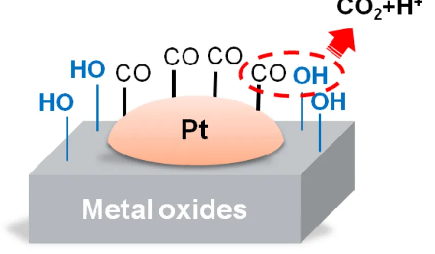
Figure 1-2 Schematic diagram illustrating the bi-functional mechanism of the Pt
nanoparticle and the metal oxide support on CO oxidation ... 4
Figure 2-2 Schematic illustration of DMFCs is shown. The MOR and ORR occur at the
anode and cathode, respectively. Electricity is made and utilized in the external circuit. ... 7
Figure 2-2 Schematic illustration of DMAFCs using alkaline system is shown. The MOR
and ORR occur at the anode and cathode, respectively. Electricity is made and utilized in the external circuit. ... 9
Figure 2-3 Schematic diagrams of the adsorption/ deprotonation process toward methanol
electro-oxidation on Pt showing the consecutive stripping of hydrogen atoms. 10
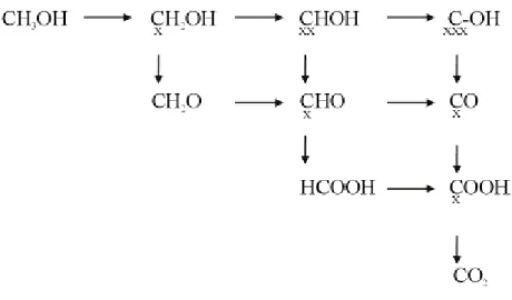
Figure 2-4 Reaction scheme for methanol oxidation showing all the possible reaction
products and possible reaction paths. ... 11
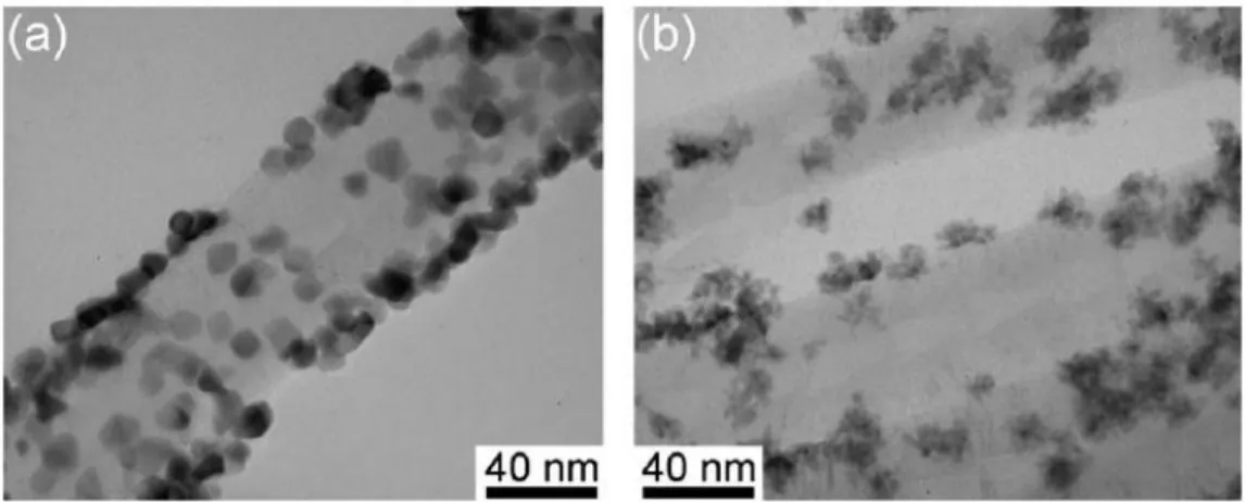
Figure 2-5 TEM images of (a) the Pt nanoparticles and (b) the Pt-Ru naoparticles decored
on CNTs. ... 12
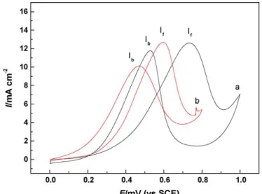
Figure 2-6 Cyclic Voltammograms of (A01) the Pt/CNTs electrode (A02) the Pt-Ru/CNTs
electrode at 20 mVs-1 in N2 saturated 0.5 M H2SO4 + 1 M CH3OH aqueous
solution. ... 13
Figure 2-7 TEM (a) and SEM (b) images of the Pt-Ru nanowire array electrode. ... 14 Figure 2-8 Cyclic voltammograms of methanol electro-oxidation for the Pt nanowire array
eletrode (a) and Pt-Ru nanowire array electrode (b) in the 0.5 M CH3OH + 0.5
M H2SO4 solution. The scan rate was 20 mVs-1. ... 14
Figure 2-9 Schematic diagrams of the novel catalysts ... 15 Figure 2-10 TEM and HRTEM images of Pt-S-ZrO2/MWCNT composites. ... 16
Figure 2-11 Chronoamperograms of various electrodes at 0.45 V in 1.0 M HClO4 + 1.0 M
CH3OH aqueous solution. ... 16
Figure 2-12 HRTEM image of CNT–CeO2/Pt catalyst. ... 17
Figure 2-13 CO stripping curves on Pt/CNTs and Pt/CeO2–CNTs recorded in 1 M HClO4.18
Figure 2-14 SEM and TEM micrographs of SnO2 NWs grown on carbon fibers of carbon
paper by thermal evaporation method. (a) SEM image showing full coverage of SnO2 NWs on fibers of carbon paper. (Inset) Fibers of bare carbon paper. (b)
TEM image showing individual SnO2 NWs. (c) TEM images showing Pt
nanoparticles electrochemically deposited onto SnO2 NWs (Inset) Pt
nanoparticles deposited onto a single SnO2 NW ... 19
Figure 2-15 CVs for methanol oxidation reaction in 1 M H2SO4 aqueous solution with 2 M
XI
30 wt % Pt/C electrode with 0.1 mg/cm2 Pt loading. Potential scan rate 50
mV/s. The current normailized on the basis of Pt loading. ... 20
Figure 2-16 CO stripping voltammetry for Pt catalyst ink electrode in 0.5 M H2SO4 for submono and saturation adlayers created by dosing of CO containing electrolyte for various periods of time. CO was dosed at 0.2 V and the scan rate was 50 mVs-1. ... 22
Figure 2-17 Cyclic voltammograms for Pd(poly) is in 0.5 M aqueous H2SO4 solution. The temperature was at 298 K and the scan rate is 50 mVs-1. The CV profiles exhibit the oxidation of Pd begins at 0.65 V vs. RHE and graduate onset of hydrogen absorption upon decrease of the potential limit from 0.4 to 0.16 V, with the process commencing at 0.3 V. ... 23
Figure 2-18 Schematic diagram illustrating the Langmuir-Hinshelwood mechanism and the Eley-Rideal mechanism. ... 24
Figure 2-19 Schematic diagram of the structure of the novel catalyst Pt-S-TiO2/CNT. ... 25
Figure 2-20 (a) Pt-4f core level XPS spectra of Pt nanoparticles supported on: (from top to bottom) TiO2, ZrO2, SiO2, CeO2. (b) Pt 4d5/2 from Pt/Al2O3. All spectra were measured after removal of the encapsulating polymer by annealing in air at 500 o C ... 27
Figure 3-1 Experimental flowchart for the fabrications and analyses of the Pt/porous TiO2, Pt/karst-Ni and Pt/PdO electrodes. ... 29
Figure 3-2 Experimental flowchart for the fabrications the Pt/TiO2 electrode. ... 30
Figure 3-3 Experimental flowchart for the fabrications the Pt/PdOelectrode. ... 31
Figure 3-4 Experimental flowchart for the fabrications the Pt/karst-Nielectrode. ... 33
Figure 4-1 SEM images for (a) the as prepared porous TiO2 thin film, (b) porous TiO2-3h thin film, (c) cross-section of the porous TiO2-3h thin film, (d) Pt nanoparticles deposited on the porous TiO2-3h thin film, (e) Pt particles deposited on the blanket TiO2 thin film, (f) Pt islands on the Ti substrate, and (g) blanket Pt thin film on the Ti substrate. ... 39
Figure 4-2 X-ray diffraction spectra of the porous TiO2 thin film annealed at various temperatures for one hour: (a) as-prepared, (b) 300oC, (c) 400oC (d) 500oC (e) 600oC and (f) 600oC for three hours. ... 41
Figure 4-3 (a) TEM and (b) HRTEM images of Pt nanoparticles on the TiO2-3h support. The lattice fringes labeled by A and B are due to the anatase (101) and the Pt(111) lattice planes, respectively. ... 42
Figure 4-4 CO stripping cyclic voltammograms of the Pt/TiO2-3h, Pt/TiO2-tf, Pt/Ti and blanket-Pt electrodes in a CO saturated 0.5 M H2SO4 solution. The scan rate was 20 mV s-1. ... 44
XII
electrodes in the 1 M CH3OH + 1 M H2SO4 solution. The scan rate was 20 mV
s-1. ... 45
Figure 4-6 Schematic diagram illustrating the synergistic effect of the Pt nanoparticle and
the anatase TiO2 support on CO oxidation on the Pt nanoparticle. ... 49
Figure 4-7 Chronoamperometry curves of the Pt/TiO2-3h, Pt/TiO2-tf, Pt/Ti and blanket-Pt
electrodes in the solution of 1 M CH3OH +1 M H2SO4 at room temperature
(~25 oC)for one hour. The oxidation potential was kept at 0.5 V vs. SCE. .. 50
Figure 5-1 SEM images of (a) the as-deposited PdO nanoflakes on a carbon fiber selected
from the carbon cloth shown in the inset; (b) a magnified SEM image of PdO nanoflakes deposited on the carbon fiber. ... 53
Figure 5-2 The Cyclic voltammogram of the PdO nanoflake thin film in the aqueous
solution of 0.5 M H2SO4. The scan rate was 20 mV s-1. ... 54
Figure 5-3 Pd (3d) XPS spectra of the PdO nanoflake thin film: (a) the as-deposited PdO
thin film; (b) the PdO thin film polarized at 0.1 V for 30 min in the 0.5 M H2SO4 solution; (c) the PdO thin film after one CV scan cycle; and (d) a
metallic Pd thin film deposited on the carbon cloth and cleaned with Ar sputtering for 400 sec. The dashed lines mark the binding energies of the Pd(0), Pd(II) and Pd(IV) states, which are referred to the literature. ... 56
Figure 5-4 The cyclic voltammogram of the PdO thin film in the aqueous solution of 1 M
CH3OH + 0.5 M H2SO4. The inset shows a CV curve with a scan range of
0.4 – 0.9 V at the tenth scan cycle. The scan rate was 20 mV s-1. ... 57
Figure 5-5 Schematic illustration of the electrochemical reaction steps for the PdO thin
film in the aqueous solution of 1 M CH3OH + 0.5 M H2SO4; (1) formation of a
metallic Pd surface layer on the PdO thin film at potentials below 0.33 V; (2) electro-oxidation of chemisorbed methanol starts around 0.33V accompanied with carbonaceous residue formation; (3) free Pd sites are oxidized at potentials above 0.45 V; (4) the MOR on the PdO thin film is completed at 0.8 V; (5) the carbonaceous adspecies are oxidized at potentials below 0.6 V in the reverse CV sweep; (6) the PdO reduction begins at ~0.45 V; (7) more methanol molecules are chemisorbed on the electrode; (8) hydrogen adsorption and desorption take place at potentials below 0 V. The dimension of the block representing the carbon residue denotes the amount of the poisoned sites. .... 58
Figure 5-6 SEM image of the PdO thin film after the pulse-electrodeposition of Pt
nanoparticles; (b) XRD spectrum of the Pt/PdO thin film shown in (a). ... 61
Figure 5-7 (a) The bright field TEM image of electrodeposited Pt nanoparticles on PdO
nanoflakes separated from the Pt/PdO electrode; (b) and (c) HRTEM images of a selected area on the edge of a nanoflake. ... 62
XIII
the aqueous solution of 1 M CH3OH + 0.5 M H2SO4. The CV curves shown in
the figure are for the fourth CV cycle. The scan rate was 20 mV s-1. ... 63
Figure 5-9 CO stripping CV curves for the Pt/PdO, the PdO thin film, the Pt/C and the
blanket Pt electrodes. The scan rate was 20 mV s-1. ... 65
Figure 5-10 (a) Pt 4f spectra of the Pt/PdO, the Pt/C and the blanket-Pt electrodes before
the electrochemical measurement; (b) the Pd 3d XPS spectrum of the
as-prepared Pt/PdO electrode. ... 67
Figure 5-11 Images of (a) the PdO nanoflake electrode and (b) the Pt/PdO electrode after
10 CV cycles in the solution of 1M CH3OH + 0.5 M H2SO4. ... 69
Figure 5-12 Chronoamperograms of the Pt/PdO electrode, the Pt/C, the blanket-Pt and the
PdO electrodes in the aqueous solution of 1 M CH3OH + 0.5 M H2SO4 at room
temperature (~25 oC) for 1 h. The oxidation potential was kept at 0.5 V vs. SCE. ... 70
Figure 6-1 SEM images of (a) the as-deposited metallic nickel thin film, (b) the
as-prepared karst-Ni thin film, (c) the karst-Ni thin film after the
pulse-electrodeposition of Pt nanoparticles, and (d) the blanket-Ni thin film with pulse-electrodeposited Pt particles. ... 74
Figure 6-2 TEM images of the karst-Ni thin film with electrodeposited Pt nanoparticles in
different magnifications (a), (b) and (c); HRTEM image of Pt nanoparticles on the karst-Ni support (d). ... 75
Figure 6-3 X-ray diffraction spectra of the as-deposited Ni thin film and the karst-Ni thin
film ... 76
Figure 6-4 Ni(2p) XPS spectra of the as-deposited Ni thin film, the as-prepared karst-Ni
thin film and a karst-Ni thin film after a 10-cycle CV scan in the aqueous solution of 1 M CH3OH + 1 M KOH. The dashed line marks the Ni 2p3/2
binding energy of metallic Ni. ... 77
Figure 6-5 Cyclic voltammogarms of methanol electro-oxidation for the Pt/karst-Ni, the
Pt/Ni and the blanket-Pt electrodes in the aqueous solution of 1 M CH3OH + 1
M KOH. The scan rate was 20 mVs-1. The current density is normalized to the sample surface area. ... 78
Figure 6-6 CO stripping cyclic voltammograms of the Pt/karst-Ni, the Pt/Ni and the
blanket-Pt electrodes in the CO saturated 1 M KOH solution. The scan rate was 20 mVs-1. The current density is normalized to the sample surface area. 80
Figure 6-7 The Pt 4f XPS spectra of the Pt/karst-Ni, the Pt/Ni and the blanket-Pt electrodes.
In the spectra of the two Ni-supported electrodes, the peak situated around 67.6 eV is due to the Ni 3p signal emitted from the Ni support. Curve fitting was carried out so that the Pt 4f7/2 binding energy for the two Ni-supported
XIV
Figure 6-8 Schematic illustration of the synergistic effect of the bi-functional mechanism
and the electronic effect for CO electro-oxidation on Pt nanoparticles adhered to the Ni support. The arrows represent negative charge transfer from the
Ni(OH)2 surface layer to the Pt nanoparticle. The gradually shaded color
indicates the degree of the induced electronic modification on the Pt nanoparticle as a result of the charge transfer. The thickness of the lines connecting CO adspecies with Pt nanoparticle represents the magnitude of the bond strength, which depends on the degree of the electronic modification and exposed surface lattice planes of the Pt nanoparticle. The reactions numbered by 1 and 2 denote CO oxidation by an OH adspecies via the L-H mechanism and by an OH- ion from the electrolyte via the E-R mechanism, respectively. The processes numbered by 3 represent that an OH surface group on the Ni(OH)2 surface layer reacts with an neighboring CO adspecies on the Pt
nanoparticle, or migrates to a free surface site (labeled by the star symbol) on the nanoparticle. The OH- ion numbered by 4 denotes the diffusion of the OH -ion toward a free surface site, which can be created by the removal of an
oxidized CO adspecies. ... 85
Figure 6-9 Ni 2p3/2 XPS spectrum of a karst-Ni thin film after a 10-cycle CV scan in the
aqueous solution of 1 M CH3OH + 1 M KOH. Curve fitting was carried out to
resolve the component peaks of metallic Ni, NiO, Ni(OH)2 and NiOOH. ... 86
Figure 6-10 Chronoamperometry curves of the Pt/karst-Ni, the Pt/Ni and the blanket-Pt
electrodes in the aqueous solution of 1 M CH3OH + 1 M KOH at room
temperature (~25 oC) for 1 h. The oxidation potential was kept at -0.3 vs. SCE. The inset shows the same chronoamperometric results but the y-axis label
“mass activity” is replaced by the current density normalized to the
electrochemical surface area. ... 88
Figure 7-1 Operation principle of photoelectrolysis cell based on TiO2/Nafion/Pt-CB
1
Chapter 1 Introduction
1.1 Introduction to fuel cells
Because of the expected shortage of fossil fuels and the urgent need of environment friendly energies, such as renewable energy resources, fuel cells receive extensive attention in recent decades. The working principle behind fuel cells strongly relies on chemical interactions between the fuels and the electrodes, and shares some common characteristics with primary batteries. Fuel cells are powerful energy sources combining numerous advantages of both conventional electricity generation engines and batteries, such as a long operation lifetime for the former and being clean and portable for the latter. Therefore, they are thought to be promising renewable energy resources to reduce the demand of traditional petrochemical energies, which will be eventually exhausted and are a major cause resulting in environmental pollution and the greenhouse effect.
In a simple fuel cell, the fuel electrochemical reaction is split into two half reactions: H2 ↹ 2H+ + 2e- (1-1)
2 1
O2 + 2H+ + 2e- ↹ H2O (1-2)
The electrons transferred from the fuel are forced to flow through an external circuit by spatially separating these reactions, thus constituting an electric current. Spatial separation is performed by utilizing an electrolyte, which is a medium that allows ions to flow but not electrons. A full fuel cell must have two electrodes separated by an electrolyte. The two electrochemical half reactions tale place in the two electrodes, respectively. In 1839, the first fuel cell, invented by William Grove, probably looked like an extremely simple H2-O2 fuel cell, as shown in fig. 1-1 [2]. This fuel cell consisted of
two electrodes dipped into an aqueous acid electrolyte, such as H2SO4 or HClO4. At the
2
(1-1). The electrons flow from anode to cathode through external circulation that connects the two electrodes. Furthermore, the H+ can flow through the electrolyte, but the electrons cannot. When the electrons reach the cathode electrode, they recombine with H+ and bubbling oxygen gas to produce water following Equation (1-2). The flowing electrons will provide power to the load, such as a light bulb, and the simple fuel cell will produce electricity.
Fuel cells are classified into five major types which are based on the kinds of the electrolyte: Phosphoric acid fuel cells (PAFC); Polymer electrolyte membrane fuel cell (PEMFC); Alkaline fuel cell (AFC); Molten carbonate fuel cell (MCFC); Solid oxide fuel cell (SOFC). They all operate at different temperature regimens, incorporate different materials, and often differ in their fuel tolerance and performance characteristics, as shown in table 1-1 [2]. PEMFCs utilize a thin polymer membrane where protons can be saturated as the electrolyte and platinum-based materials are the prevailing catalysts for cathode and anode. Pure hydrogen and oxygen are used as the fuel in anode and cathode electrode, respectively. However, liquid fuels such as methanol, ethanol or formic acid are also considered because difficulties in the aspeck of storage and transportation is the extreme
3
weakness of hydrogen. In addition, direct methanol fuel cells (DMFCs) use methanol of high energy density as the fuel, and methanol has been extensively considered as renewable power source and is an attractive candidate for low-power portable fuel cell applications. The advantages of DMFCs comparing with several kinds of fuel cells are the operation at low temperatures, easy fuel storage, and the reduced volume and weight in equipment. Even if there are many advantages, DMFCs used Pt as the catalysts in the practical commercialization is also impeded by many difficulties such as methanol crossover, the high cost of the Pt catalyst, the inaction of the oxygen reduction reaction and the low efficiency of the electroactivity of MOR due to CO poison.
Table 1-1 Description of major fuel cell types [2]
PEMFC PAFC AFC MCFC SOFC
Electrolyte Polymer membrane Liquid H3PO4 (immobilized) Liquid KOH (immobilized) Molten carbonate Ceramic Charge carrier H+ H+ OH- CO32- O 2-Operating temperature 80 oC 200 oC 60-220 oC 650 oC 600-1000 oC Catalyst Platinum Platinum Platinum Nickel Perovskites (ceramic) Cell
components
Carbon based
Carbon based Carbon based Stainless based Ceramic based Fuel compatibility H2, methanol H2 H2 H2, CH4 H2, CH4, CO
1.2 Motivation
As far as MOR is concerned, the most widely studied subject is how to enhance the electrocatalytic activity of anode with a minimized Pt loading. Researchers try to reduce the size and optimize the distribution of Pt nanoparticles to minimize the use of t he preious Pt catalyst and increase concurrently the electroactivity surface area (ESA) for methanol oxidation on the catalyst. Another major approach to improving the MOR electroactivity
4
is to increase the resistance of Pt catalysts against CO poisoning, which results from catalytic site blocking by carbonaceous byproducts due to incomplete methanol oxidation. On the other hand, to improve the CO tolerance, Pt-based binary or ternary alloys commonly used as catalyst in considerable studies, in particular Pt-Ru, are to enhance CO electro-oxidation via the bi-functional mechanism, which governs the electro-oxidation reaction of the carbonaceous byproducts with neighboring OH adspecies, and/or the so-called electronic effect [3-10]. A fast removal rate of the carbonaceous adspecies can continuously create free adsorption sites for methanol molecules, thus resulting in a high reaction rate of methanol electro-oxidation. The removal rate speedily of the carbonaceous adspecies can be continuously created the free adsorption sites for methanol molecule which results in the high reaction rate of methanol electro -oxidation. More transition metals and metal oxides as a promoter or the catalyst support are, more the CO tolerance of the Pt catalyst can be gained effectively which is based on a similar principle [3-22].
Figure 1-2 schematically illustrates the likely reaction steps of CO oxidation on the Pt nanoparticles via the bi-functional mechanism. Dissociative adsorption of water
Figure 1-2 Schematic diagram illustrating the bi-functional mechanism of the Pt nanoparticle and the metal
5
molecules on the metal oxide support creates OH surface groups. The groups adjacent to Pt nanoparticles may readily oxidize CO groups bonded on the Pt surface. In the thesis, we used TiO2, PdO and NiO nanostructured thin films as the support of Pt nanoparticles and
studied the effect of the oxide supports on the enhancement of the electrocatalytic activity of the Pt catalyst toward MOR [20, 23]. We ascribed the observed electroactivity enhancement to the synergism of the electronic effect and the bi-functional mechanism, which was a result in electronic and chemical interactions between the hydrous oxides and the Pt nanoparticles.
6
Chapter 2 Literature Review
2.1 Direct methanol fuel cells (DMFCs)
Direct methanol fuel cells (DMFCs) are very attractive for the mobile power source
application, such as automotive systems and portable electronics, in the past decade because they can be operated at low temperatures and have a high energy density and a long span-life. They are lightweight with a simple system design based on PEMFC technology, utilizing hydrogen as fuel. Nevertheless, while the DMFCs work, methanol is directly fed as fuel into the fuel cell systems without converting to hydrogen. It mainly resolves the difficulty and the danger in the aspect of storing and transporting of hydrogen. Besides, methanol can be produced easily in natural from solid (coal), liquid (crude oil) or gas (natural gas) and has a high energy density.
Although DMFCs possess many merits as a power source, practical commercialization still faces several fundamental materials challenges, such as degraded electroactivity of MOR due to CO poisoning, sluggish oxygen reduction reaction, methanol crossover and the high cost of the Pt catalyst. As far as the methanol oxidation reaction (MOR) is concerned, major challenges receiving particular attention are a higher electrocatalytic activity with a minimized Pt catalyst loading and a better resistance against the CO poisoning effect. The widely adopted method to improve the electrocatalytic mass activity of the precious Pt catalyst toward MOR is to reduced the size and optimize the distribution of Pt nanoparticles to minimize the use of the precious Pt catalyst and concurrently increase the electroactivity surface area (ESA) [11, 12, 24-28].
A schematic diagram of a DMFC is presented in Fig. 2.1. At the anode, methanol and water react to produce carbon dioxide, protons and electrons by the catalyst layer in equation (1). Platinum (Pt) or platinum alloy are usually utilized as catalytic material in
7
anode electrode. The protons produced at the anode will be through the polymer electrolyte membrane to the cathode and react with oxygen. Nafion® membranes by DuPont are the most investigated and employed as the polymer electrolyte membrance for PEMFCs or DMFCs. These membranes consist of a poly-tetrafluoroethylene (PTFE) based structure and have a high protons conductivity. At the cathode, Pt is also utilized as the catalyst; oxygen reacts on the electrodes with protons, which come from the anode, and form water as shown in equation (2). The oxygen reduction reaction (ORR) proceeds via certain steps in which molecular oxygen dissociates at the catalyst surface and recombines with protons (hydrogen ions) to form water [29]. The electrons, which is produced at the anode and receive at the cathode carry the free energy change of the oxidation and the reduction chemical reaction, and transport through the external circuit where the electricity is made and utilized [30]. A methanol/water liquid mixture diffusion takes place in the gas diffusion layer (GDL), which are usually carbon substrate (carbon paper or carbon cloth) and can uniformly disperse methanol in the anode and oxygen in the cathode. The MOR, ORR and overall reaction of DMFCs can be expressed by the following reactions: [29, 30]
Figure 2-1 Schematic illustration of DMFCs is shown. The MOR and ORR occur at the anode and cathode,
8 CH3OH + H2O → CO2 + 6H+ + 6e- anode reaction (2-1) 2 3 O2 + 6H+ + 6e- → 3H2O cathode reaction (2-2) CH3OH + H2O + 2 3 O2 → CO2 + 3H2O overall reaction (2-3)
2.2 Direct methanol alkali fuel cells (DMAFCs)
Although extensive study on DMFCs has been being carried out for several decades, practical commercialization of DMFCs still faces many challenges associated with materials and technical shortcomings, including high cost of Pt-based electrocatalysts, low electroactivity of methanol oxidation reaction (MOR), poor kinetics of oxygen reduction reaction (ORR), and methanol crossover [29, 31]. Among various attempts to improve electrochemical performance of DMFCs, the study on the improvement in the electrocatalytic activity of Pt toward MOR receives the most attention. One major approach to improving the MOR electroactivity is to increase the resistance of Pt catalysts against CO poisoning, which results from catalytic site blocking by carbonaceous byproducts due to incomplete methanol oxidation [29, 30, 32].
Pt is known to have a higher CO tolerance in alkaline media than in acidic media, and thus exhibit better electrocatalytic performance for methanol oxidation in alkaline electrolytes [33, 34]. The better CO tolerance in alkaline media is generally ascribed to the abundance of OH- ions in the electrolyte, which can effectively oxidize carbonaceous adspecies on the Pt catalyst via the Eley-Rideal (E-R) mechanism [35, 36]. Because the electrocatalytic activity of Pt toward MOR can be readily improved by using alkaline electrolytes, direct methanol alkali fuel cells (DMAFCs), which is an alkali analogue of DMFCs, have recently received much interest. Besides, compared with DMFCs, DMAFCs have a faster oxygen reduction kinetics [29, 37] and less methanol crossover [38].
9
DMAFCs operate using anion-exchange membranes, which provided a suitable ionic conductivity, as the electrolyte. A schematic of the electrochemical reaction and the process of transportation in the DMAFCs are shown in Fig 2-2. Because the process of the chemical reactions is in alkaline media, the MOR and ORR will be with slight differences in the alkaline media and acidic media. At the cathode, oxygen reacts with water and electrons, which are produced at the anode, and OH- ions will be produced. The OH- ions will migrate through the anion exchange membrane, such as Morgane® ADP hydroxide ion conducting membrane [38], from the cathode to the anode. At the anode, methanol reacts with OH- ions, which received from the cathode electrode or offered by KOH or NaOH electrolyte, and produce carbonates, water and electrons. The same process as DMFCs, the electrons transport through the external circuit from the anode to cathode carrying the electricity. The MOR, ORR and overall reaction of DMAFCs in alkaline system can be expressed by the following reactions: [38]
CH3OH + 8OH- → CO32- + 6H2O + 6e- anode reaction (2-4)
Figure 2-2 Schematic illustration of DMAFCs using alkaline system is shown. The MOR and ORR occur at the
10 2
3
O2 + 3H2O + 6e- → 6OH- cathode reaction (2-5)
CH3OH + 2OH- +
2 3
O2 → CO32- + 3H2O overall cell reaction (2-6)
2.3 Electrocatalytic methanol oxidation reaction
Only a few materials, such as Pt and Pd, are found to be capable of adsorbing and oxidizing methanol. Pt-based materials contribute a high enough activity and stability to be attractive as catalysts toward methanol electro-oxidation. The overall reaction mechanism for the methanol oxidation reaction is shown in reaction (2 -1). The methanol oxidation reaction proceeds on Pt based catalysts followed by several steps of deprotonation. Schematic diagrams of the adsorption/ deprotonation process on is shown in Figure 2-3 [29].
During the methanol oxidation, CO is formed on Pt surface. The CO species can block the surface of the catalyst, such as Pt or Pd, and obstruct the MOR. Therefore, to improve the CO tolerance, considerable studies used Pt-based binary or ternary alloys as the catalyst, in particular Pt-Ru to enhance CO electrro-oxidation. To facilitate CO removal by oxidation to CO2, it can be achieved by using oxygen containing species either
from the water in solution or hydroxide ions [29].
Figure 2-4 shown a scheme of the possible reactions for MOR and their products [29]. The possible reaction pathways and products are shown in the scheme. Each reaction step
Figure 2-3 Schematic diagrams of the adsorption/ deprotonation process toward methanol electro -oxidation on
11
denotes the transfer of one electron. Oxidation by adsorbed OH occurs in the perpendicular direction; stable compounds are located on the hypothenus; and dehydrogenation occurs in the direction from left to right. The schematic diagram illustrates that CO is an intermediate product during the methanol electro-oxidation.
2.4 Anode materials of DMFCs
Platinum has a superior electrocatalytic activity toward methanol oxidation reaction (MOR) and, therefore, Pt or Pt-based alloys are fundamentally the most preferred catalyst used in direct methanol fuel cells (DMFCs). On the other hand, to improve the CO tolerance, considerable studies used Pt based binary or ternary alloys, such as Pt-Ru, Pt-Ni and Pt-Pd, as the catalyst to enhance CO electro-oxidation via the bifunctional mechanism and/or the so called electronic effect [3-10]. Metal oxides, such as TiO2, CeO2, SnO2 and
RuO2, can also effectively improve the CO tolerance of the Pt catalyst when they used as a
promoter or the catalyst support based on a similar principle [13-15, 20-22, 39].
Figure 2-4 Reaction scheme for methanol oxidation showing all the possible reaction products and possible
12
2.4.1 Pt-Ru nanoparticles on carbon nanotubes
Carbon nanotubes (CNTs) are attractive very much for electrochemical and catalytic applications because their uniform structure, electronic properties, electrochemical stability in both acidic and alkaline media. In the past few years, Pt or Pt-Ru nanoparticles decorated on CNTs are extensively utilized as electrode materials for the anode of DMFCs. Tsai et al. introduced ethylene glycol (EG) as a reducing agent for potentiostatic electrodeposition of Pt or Pt-Ru on CNTs, which were directly grown on carbon cloth by thermal CVD [9]. EG contributes the dechlorination of Pt or Ru precursor salts and promotes the formation of Pt or Pt-Ru nanoparticles. It is also used to prevent the particles from agglomeration. Figure 2-3 exhibits the TEM micrographs of (a) the Pt nanoparticles and (b) the Pt-Ru nanopaarticles decored on CNTs. The mean particle size of the Pt/CNTs and the Pt-Ru/CNTs are 9.5 nm and 4.8 nm, respectively. The addition of EG favorably reduced the particle size of Pt and Pt-Ru catalysts and prevented them from the serious agglomerations.
The Cyclic voltammograms of (A01) the Pt/CNTs and (A02) the Pt-Ru/CNTs at 20 mVs-1 in N2 saturated 0.5 M H2SO4 + 1 M CH3OH were shown in Figure 2-4.
Pt-Ru/CNTs exhibited a relatively higher If/Ib ratio and mass activity than the Pt/CNTs.
13
For the Pt-Ru/CNTs electrode, the CO desorption peak current densities during the reverse scan (Ib) was lower than it of Pt/CNTs. It indicated that the presence of Ru indeed
enhances the CO tolerance on the Pt surface and the methanol oxidation reaction of the electrode.
2.4.2 Pt-Ru nanowire array electrodes
Zhao et al. prepared Pt and Pt-Ru nanowire array electrodes by DC electrodeposition of Pt and Ru into the pores of an anodic aluminum oxide (AAO) template on a Ti/Si substrate [8]. AAO films were grown on a Ti/Si substrate and used as a template to synthesize a high surface area and ordered nanowire array electrode for MOR. The electrochemical measurements were performed in an 0.5 M CH3OH + 0.5 M H2SO4
aqueous solution using the nanowire array as the working electrode. Figure 2-7 (a) shows a TEM image of the Pt-Ru nanowires and reveals that the nanowires obtained on the Ti/Si substrate are the regular size and the continuation. From SEM image (Figure 2.7 (b)), many clusters protrude from the Ti/Si substrate and provide a high surface area electrode. It also indicates that the nanowire array electrode has 10 cm2 of Pt area per cm2 of substrate electrode area, from the diameter and the length of the nanowires, and is higher than the
Figure 2-6 Cyclic Voltammograms of (A01) the Pt/CNTs electrode (A02) the Pt-Ru/CNTs electrode at 20 mVs-1
14
Pt-Ru black (2.1 cm2 Pt/ cm2).
The CV curves of methanol oxidation for the Pt (a) and the Pt-Ru (b) nanowire array electrode surface in a solution of 0.5 M CH3OH + 0.5 M H2SO4 were shown in figure 2-8.
For the Pt-Ru nanowire array electrode surface, the peak potential for methanol oxidation shifted negatively by over 130 mV compared with the Pt nanowire array electrode. The If/Ib ratio of 1.28 for Pt-Ru nanowire array electrode is also higher than that of Pt (1.08).
The negative shift of peak potential and the higher If/Ib ratio can be indicated the improved
CO tolerance of the Pt-Ru nanowire array electrode. The Pt-Ru nanowire array electrode
Figure 2-8 Cyclic voltammograms of methanol electro-oxidation for the Pt nanowire array eletrode (a) and
Pt-Ru nanowire array electrode (b) in the 0.5 M CH3OH + 0.5 M H2SO4 solution. The scan rate was 20 mVs-1.
15
also has a higher current density after 500s in the chronoamperograms measurement. That can be ascribed by the bi-functional mechanism in which the reaction occurs between strongly bound Pt3CO species and OH on the neighboring Ru sites.
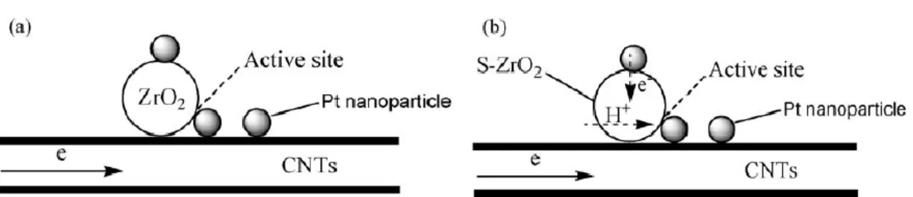
2.4.3 Sulfated ZrO
2/MWCNT composited as supports of Pt catalysts
Sulfated zirconia supported on multi-walled carbon nanotubes as new supports of Pt catalyst (Pt-S-ZrO2/ MWCNT) was synthesized, aiming at enhancing electron and proton
conductivity and also catalytic activity of Pt electrocatalyst in terms of larger concentrations of ionizable OH groups on surfaces [40]. Pt-S-ZrO2/MWCNT catalyst
show higher catalytic activity for methanol electro-oxidation compared with Pt catalyst on nonsulfated ZrO2/MWCNT support and commercial Pt/C (E-TEK). Sulfated ZrO2 is
superacid and good proton conductor, as support for Pt catalyst may increase the utilization of the Pt catalyst for methanol oxidation because of the proton conductivity shown as in Fig. 2-9. On the other hand, the oxidation of CO requires an adsorbed OH species adjacent to the adsorbed CO. The SO42- group on ZrO2 surface will increase the hydrophilic
properties of ZrO2 and the more dissociative hydroxyl of H2O absorbed on the solid
superacid than that non-sulfated ZrO2, thus sulfated ZrO2 can more easily transform COads
to CO2 by the hydroxyl on its surface according to the bi-functional mechanism, releasing
the active sites of Pt for further electrochemical reaction.
16
Figure 2-10 shows the typical TEM and HRTEM images of the Pt-S-ZrO2/ MWCNT
composites. It can be seen that the Pt and S-ZrO2 nanoparticles are relatively uniformly
distributed on the sidewalls of the MWCNTs. The HRTEM micrograph reveals that both Pt and S-ZrO2 nanoparticles attached on the sidewalls of the MWCNTs. Fig. 2-11 shows that
the pattern of current decay was different for each catalyst. For both the catalysts, the current decayed continuously even after 1 h, supposedly because of catalyst poisoning by
Figure 2-10 TEM and HRTEM images of Pt-S-ZrO2/MWCNT composites.
Figure 2-11 Chronoamperograms of various electrodes at 0.45 V in 1.0 M HClO4 + 1.0 M CH3OH aqueous
17
the chemisorbed carbonaceous species and the depletion of OH sites which are responsible for oxidation of CO. The Pt-S-ZrO2/ MWCNT was able to maintain the highest current
density throughout all the ranges up to 3600 s among all the catalysts. The catalytic activity of Pt-S-ZrO2/MWCNT catalysts was much higher than that of Pt-ZrO2/MWCNT
and Pt/C. This would be due to the strengthening of both the bi-functional mechanism and higher electron and proton conductivity of S-ZrO2/ MWCNT composites.
2.4.4 Preparation of Pt/CeO
2-CNT through spontaneous adsorbing Pt
nanoparticles onto CNTs
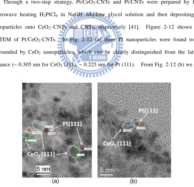
Through a two-step strategy, Pt/CeO2-CNTs and Pt/CNTs were prepared by first
microwave heating H2PtCl6 in NaOH ethylene glycol solution and then depositing Pt
nanoparticles onto CeO2–CNTs and CNTs, respectively [41]. Figure 2-12 shown the
HRTEM of Pt/CeO2-CNTs. In Fig. 2-12 (a) three Pt nanoparticles were found to be
surrounded by CeO2 nanoparticles, which can be clearly distinguished from the lattice
distance (~ 0.305 nm for CeO2 (111), ~ 0.225 nm for Pt (111). From Fig. 2-12 (b) we can
18
clearly see the Pt nanoparticles on sidewall of CeO2-CNTs adjacent to CeO2 particles.
Because CO electro-oxidation is viewed as a rate-determining step during methanol electro-oxidation, CeO2 would promote methanol electro-oxidation on Pt-based catalysts
according to the bi-functional mechanism. To verify the role of CeO2 in Pt/CeO2-CNTs,
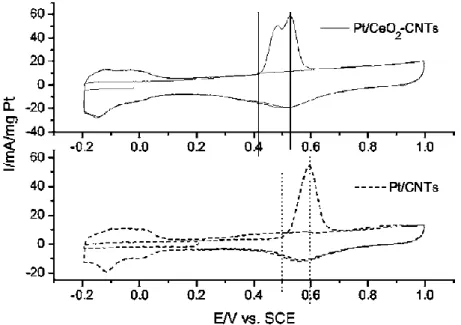
Wang et al. performed the potentiodynamic and potentiostatic electro-oxidation of CO adlayer on Pt, as shown in Fig. 2-13 [41]. The CO stripping on Pt/CeO2-CNTs starts at
0.41 V, 0.08 V lower than 0.49 V on Pt/CNTs. In addition, the peak potential of CO stripping lies at 0.52 V on Pt/CeO2-CNTs while lying at 0.6 V on Pt/CNTs. Such results
indicate that CO can be electro-oxidized more easily on Pt/CeO2-CNTs than on Pt/CNTs.
In Fig. 2-13, two peaks on Pt/CeO2–CNTs, possibly because that there are different contact
states between Pt and CeO2. The results in Fig. 2-13 indicate that CO can be
electro-oxidized on Pt/CeO2-CNTs more easily than on Pt/CNTs. This is possibly because
CeO2 can provide oxygen-containing group to electro-oxidize CO, the major intermediate
during methanol electro-oxidation. Therefore, CeO2 can be viewed as promising
cocatalyst for methanol electro-oxidation on Pt-based catalysts.
19
2.3.5 Pt nanoparticles on SnO
2nanowire-based electrodes
Because carbon nanotubes (CNTs) and nanofibers (CNFs) have unique properties, such as high surface area, good electronic conductivity, strong mechanical properties, and chemical stability, they have attracted great attention as promising catalyst supports. A number of research groups have demonstrated the advantages of using CNTs or CNFs as supports to better disperse Pt and its alloys for oxygen reduction and methanol oxidation reaction. In particular, the nanotube-based 3D electrode structure has shown very promising implications. Unlike CNTs, nanowires (NWs) can be made of various
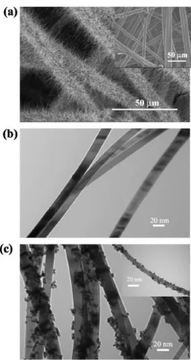
Figure 2-14 SEM and TEM micrographs of SnO2 NWs grown on carbon fibers of carbon paper by thermal
evaporation method. (a) SEM image showing full coverage of SnO2 NWs on fibers of carbon paper. (Inset)
Fibers of bare carbon paper. (b) TEM image showing individual SnO2 NWs. (c) TEM images showing Pt
nanoparticles electrochemically deposited onto SnO2 NWs (Inset) Pt nanoparticles deposited onto a single
20
compositions of materials and they have solid cores. NWs have demonstrated superior electrical, optical, mechanical, and thermal properties. Metal oxide NWs have unique advantages as supports for dispersing noble metal nanoparticles such as Pt for practical applications.
Saha et al. prepared the composite electrodes by electrochemical deposition of Pt nanoparticles onto the surface of SnO2 nanowires directly grown on the carbon fibers of a
carbon paper [22]. In the comparison to a standard Pt/C electrode, the nanowire-based electrode exhibited higher electrocatalytic activity both for oxygen reduction reaction and methanol oxidation reaction. Figure 2-14 shows the SEM and TEM images of the SnO2
NWs grown on a commercially available carbon paper backing used in fuel cell applications. As shown in fig. 2-14 (a), a thin layer of high-density SnO2 NWs completely
cover the surface of the carbon fibers in the carbon paper. Figure 2-14 (b) shows that the NWs have a straight-line morphology. Figure 2-14 (c) presents the TEM image of the Pt nanoparticles electrochemically deposited on the SnO2 NWs. The successful deposition of
Figure 2-15 CVs for methanol oxidation reaction in 1 M H2SO4 aqueous solution with 2 M MeOH at Pt/SnO2
NW. carbon paper with 0.12 mg/cm2 Pt loading and standard 30 wt % Pt/C electrode with 0.1 mg/cm2 Pt loading. Potential scan rate 50 mV/s. The current normailized on the basis of Pt loading.
21
Pt nanoparticles indicates a good electrical contact between the SnO2 NWs and the carbon
fibers. Furthermore, the electrochemical performance of the Pt/SnO2 NW/carbon paper electrode for methanol oxidation was also examined and the corresponding results are shown in Fig. 2-15. Compared with the Pt/C electrode, the oxidation peak current for the Pt/SnO2 NW/ carbon paper electrode is about 71.5 mA/mgPt, which is higher than that of
the Pt/C electrode, suggesting a higher utilization of Pt for methanol oxidation reaction. The significant improvement in catalytic activites of the Pt/SnO2 NW/carbon paper
composite electrode may be attributed to the following: (1) the unique 3D structure and electronic properties of SnO2 NWs, (2) strong interaction between Pt catalyst particles and
the SnO2 NW surface, (3) synergies resulting from the combined properties of Pt
nanoparticles and SnO2 NW supports, and (4) low impurities of SnO2 NW compared to
Vulcan carbon XC-72 which contains a significant amount of organosulfur impurities, which can poison the Pt metal.
2.5 Adsorbed CO on Pt surface
CO adlayers of different coverages were produced by a dosing preocedure and their electrooxidative removal was studied by Koponen et al [42]. Figure 2-16 shown that the CO stripping voltammetry for pure catalyst ink electrode in 0.5 M H2SO4 for submono and
saturation adlayers which is created by dosing of CO containing electrolyte for various periods of time. CO-oxidation processes present at 0.79 and 0.85-0.88 V. For CO on Pt(111), two main oxidation peaks are found, one minor and stationary at intermediate coverages, and one that shifts to the higher potential as a function of increasing CO coverage. The potential values of the stationary are 0.75 V and 0.83 - 0.88 V for the shifting peak. The stationary peak takes place at saturation coverage for the Pt(111) electrode. The stationary low potential peak may be contributed by (110) sites on the
22
crystallite; for saturated adlayers of CO on Pt(110) a single oxidation peak at 0.75 V is found. Another possibility may result from the oxidation of CO on edge sites on Pt (111) planes of the crystallite. The behavior of CO adsorbed on edge sites is similar to the CO present in loosely packed submonolayers on Pt(111) electrodes and this results oxidized at a lower potential.
2.6 Electrochemical behavior of Palladium electrode
Palladium presents high catalytic activity towards several electrochemical processes, such as the methanol oxidation reaction (MOR), hydrogen absorption and adsorption and the hydrogen evolution reaction (HER). The crucial difference characteristic between Pd and Pt is the capability of adsorbing the hydrogen [43]. The hydrogen absorption into Pd takes place in the potential range of the under potential deposition of hydrogen (UPD H). However, desorption of hydrogen occurs at potentials higher that the onset potential of HER. On the other hand, the potential range of hydrogen absorption and adsorption is depended on the different metallic alloys and should be carried out by CV measurement.
Figure 2-16 CO stripping voltammetry for Pt catalyst ink electrode in 0.5 M H2SO4 for submono and
saturation adlayers created by dosing of CO containing electrolyte for various periods of time. CO was dosed at 0.2 V and the scan rate was 50 mVs-1.
23
Hydrogen adsorptions also one of the factors influencing the shape of CV profiles. Grden et al. exhibited a typical CV profile of Pd(poly) electrode in aqueous H2SO4 [43].
Figure 2-17 reveals that the hydrogen absorption and adsorption take place at the same potential range and commence at ca. 0.3 V vs. RHE. It also exhibits that the oxidation of Pd occurs at ca. 0.65 V vs. RHE and the reduction of Pd oxide starts at ca. 0.85 V vs. RH E. In the case of Pd metal, the potential region of the metal oxidation and the oxide reduction is not the same, as shown in figure 2-17. The electrochemical behavior is the nature of the surface compound formed and then reduced. Its chemical composition and structure depend on the oxidation conditions. Palladium oxides are prevailing materials and act as catalysts in various electrochemical studies but sometimes also as inhibitors in some processes, such as oxygen reduction reaction (ORR). The electro-oxidation of Pd and reduction of Pd oxide lead to changes in the surface morphology because soluble Pd compounds or oxide may generate during the electro-dissolution of Pd.
Figure 2-17 Cyclic voltammograms for Pd(poly) is in 0.5 M aqueous H2SO4 solution. The temperature was
at 298 K and the scan rate is 50 mVs-1. The CV profiles exhibit the oxidation of Pd begins at 0.65 V vs. RHE and graduate onset of hydrogen absorption upon decrease of the potential limit from 0.4 to 0.16 V, with the process commencing at 0.3 V.
24
2.7 Bi-functional mechanism
2.7.1 Langmuir-Hinshelwood mechanism and Eley-Rideal mechanism
In the bi-functional mechanism model, hydroxyl surface groups can oxidize adjacent CO adspecies on the Pt catalyst, thereby avoiding CO poisoning. The reaction mechanism can be described by the Langmuir-Hinshelwood mechanism. In an Eley-Rideal surface reaction, the reaction product is formed by direct collision of a reactant species from the solution phase with an adspecies. In the case of CO electro-oxidation in the KOH solution, the carbonaceous adspecies on the Pt surface can be readily oxidized by the abundant OH -ions in the electrolyte [23]. The CO electro-oxidation reaction does not only lie in the surface concentration of OHad species and COad (L-H mechanism), but is strongly affected
between the COad and OH
-
ions from the electrolytes (E-R mechanism).
Poisoning of the Pt surface by CO-like species produced during methanol oxidation is the major reason for the low rate of reaction. In order to solve the problem, Pt-based alloys or Pt/metal oxide composites are employed as a catalyst to increase the MOR activity and CO tolerance of electrode, based on a bi-functional mechanism. Song et al.
Figure 2-18 Schematic diagram illustrating the Langmuir-Hinshelwood mechanism and the Eley-Rideal
25
synthesized a new carbon nanotube-supported sulfated TiO2 and Pt (Pt-S-TiO2/CNT) by
improved sol-gel and ethylene glycol reduction methods [44]. Careful structural design allowed the Pt nanoparticles to homogeneously disperse on a sulfated TiO2 layer, which
means that all of the Pt nanoparticles could be in direct contact with sulfated TiO2. This
special catalyst structure, as shown in Fig. 2-19, and the high proton conductivity of sulfated TiO2 increased the catalytic activity and CO tolerance of Pt for methanol
electro-oxidation. The CO stripping voltammograms showed that addition of sulfated TiO2 is more beneficial for CO electro-oxidation. This can be attributed to the presence of
more absorbed OH (OHad) on the S-TiO2/CNT electrode and the carefully designed
structure of Pt-S-TiO2/CNT electrode. These two factors are favorable for a bi-functional
mechanism (L-H mechanism).
2.7.2 Surface electrochemistry of CO on Pt
Although the nature and adsorption site occupancy of COad are strongly dependent on
the applied potential, the mechanism for COad oxidation on Pt (111) is independent of
electrode potential; e.g., COad reacts with oxygen containing species through either a
non-competitive or competitive Langmuir-Hinshelwood type reaction to form CO2. The
physical state of oxygen-containing species is still uncertain (bulk H2O, adsorbed H2O or
adsorbed OH). Markovic et al. have proposed that COad is oxidized by OHad, the latter
26
species resulting from oxidative water decomposition in acid solution or from OH -discharge in alkaline solution [45]:
COad + OHad = CO2 + H+ +e- (2-7)
Nevertheless, regardless of the true nature of the oxygen-containing species it was suggested that the kinetics of reaction do not depend only on the surface concentration of COad and OHad species, but are strongly affected by a delicate balance between the
coverage of and anions from electrolytes.
Recall that although the nature of COad changes with electrode potential, the
mechanism for COad oxidation on Pt (hkl) follows the L-H reaction mechanism in the entire
potential range [45]. Bergelin et al. suggested that in the preignition potential region COad
oxidation in CO free solution cannot proceed through the L-H mechanism, but rather through an Eley-Rideal mechanism, i.e. reaction between COad and “activated” water
molecules in the electrical double-layer [46]. Markovic et al. proposed that CO oxidation on Pt(111) will be considered to proceed through the L-H mechanism, in which the kinetics are strongly dependent on the delicate balance between the surface coverage of COad, OHad
and anions from supporting electrolytes [35].
2.8 Charge transfer between Pt particles and metal oxide support
Croy et al. presented the decomposition of methanol over Pt nanoparticles supported on a series of oxide powder [47]. The samples tested may be roughly grouped in two categories consisting of large and small Pt particles deposited on reducible (CeO2, TiO2)
and non-reducible (SiO2, ZrO2, Al2O3) support. Figure 2-20 shows XPS spectra of Pt
deposited on the different oxide powder supports measured after annealing at 500oC. In fig. 2-13 (a), the solid lines indicate the positions of the main core-level peaks of metallic Pt at 71.1 eV (4f7/2) and 74.3 eV (4f5/2), the dashed lines Pt2+ in PtO (73.3 and 76.6 eV), and
27
the dotted lines Pt4+ in PtO2 (75.0 and 78.8 eV). For the Pt/TiO2 sample, it is
predominantly metallic with the 4f7/2 appearing at ~ 70.5 eV. This corresponds to a
negative binding energy shift of ~ 0.6 eV with respect to the bulk value of 71.1 eV. Such negative energy shifts can be explained by charge transfer to the particle from the support due to delocalized electron distributions arising from oxygen vacancies, or small particles with a large number of surface atoms having reduced coordination number. The Pt/CeO2
sample appears highly oxidized (mainly Pt4+) and the higher binding energies indicate a string interaction between the CeO2 support and the Pt particles. The possible formation
Figure 2-20 (a) Pt-4f core level XPS spectra of Pt nanoparticles supported on: (from top to bottom) TiO2,
ZrO2, SiO2, CeO2. (b) Pt 4d5/2 from Pt/Al2O3. All spectra were measured after removal of the encapsulating
28
of Pt-Ce alloys might explain the anomalously large binding energies observed in the XPS data of these samples.
The XPS data indicate that for similarly sized particles that state of oxidation of Pt depends on the support. Because all samples underwent identical thermal treatments, the stability of Ptδ+ species can be affected by the choice of support. This suggest that for MeOH decomposition, or perhaps in general, for reactions not involving the dissociation of O2, the reducibility of the support plays a secondary role to the more important parameters
of particle size and oxidation state of Pt. The role of the support is that of a stabilizer, a provider of preferential/additional sites of interaction, and a mediator among the different oxides of Pt.
![Table 1-1 Description of major fuel cell types [2]](https://thumb-ap.123doks.com/thumbv2/9libinfo/8568366.188724/19.892.117.829.535.855/table-description-of-major-fuel-cell-types.webp)

![HPSH [ 氧化數平衡反應式係數 ]](data:image/gif;base64,R0lGODlhAQABAIAAAP///wAAACH5BAEAAAAALAAAAAABAAEAAAICRAEAOw==)