行政院國家科學委員會專題研究計畫 成果報告
滑軌式及具複合鏈六自由度等向性並聯式機器人之設計,分 析及製作
研究成果報告(精簡版)
計 畫 類 別 : 個別型
計 畫 編 號 : NSC 96-2221-E-011-110-
執 行 期 間 : 96 年 08 月 01 日至 97 年 07 月 31 日 執 行 單 位 : 國立臺灣科技大學機械工程系
計 畫 主 持 人 : 蔡高岳
計畫參與人員: 碩士班研究生-兼任助理人員:林益偉 碩士班研究生-兼任助理人員:陳逸儒 博士班研究生-兼任助理人員:李庭官
報 告 附 件 : 出席國際會議研究心得報告及發表論文
處 理 方 式 : 本計畫可公開查詢
中 華 民 國 97 年 08 月 08 日
行政院國家科學委員會專題研究計畫成果報告
滑軌式及具複合鏈六自由度等向性並聯式機器人之設計,分析及製作
計畫編號:NSC 96-2221-E-011-110-
執行期限:96 年8 月 1 日至 97 年 7 月 31 日
主持人:蔡高岳 國立台灣科技大學 共同主持人:
計畫參與人員:李庭官、陳逸儒、林益偉
國立台灣科技大學
中文摘要
以等向性產生器設計六自由度等向性機器人 不但易於使用而且為一非常有效率之方法,而 且一等向性產器可輕易的導出很多等向性串 聯或並聯式機器人。目前所使用之等向性產生 器具有一個由產生器上之參考點到達產生器 上六條直線之距離均相同之共同特性,因此由 這些產生器所得到之並聯機器人其參考點至 機器人上六根連桿之距離均相同,而串聯機器 人之參考點至六旋轉軸之距離亦相同。由於此 幾何限制使我們無法獲得更多更具實用性之 等向性設計。本計畫提出求得新等向性產生器 之方法,此方法所得到之產生器不受到上述之 幾何限制,而且此新方法容許我們設定工作參 考點之位置、機器人之大小以及形狀。計畫中 提出相當多個新式產生器並用來設計具實用 價值之傳統式以及非傳統式(滑軌式及具複合 鏈)之六自由度等向性並聯式機器人。
關鍵詞:六自由度並聯式機器人,最佳化設 計,操控性,等向性產生器
Abstract
Developing 6-DOF isotropic manipulators using isotropic generators is simple and efficient, and isotropic generators can be employed to develop serial, redundant, or parallel isotropic manipulators. An isotropic generator consists of a reference point and six straight lines. The existing generators, however, have one common geometric constraint: the reference point is equidistant from the six straight lines. Some practical isotropic designs might not be obtained
due to this constraint. This work proposes methods for developing new isotropic generators. The generators thus developed are not subject to the constraint, and the new methods allow us to specify the location of the tool center point, the size of the platform or the base, or the shape of isotropic parallel manipulators. Many new generators are presented to develop 6-DOF parallel manipulators with different shapes or different types of kinematic chains.
KEYWORDS: 6-DOF parallel manipulator;
optimum design; dexterity; isotropic generator.
1. INTRODUCTION
A manipulator can control equally well in all directions, and sensitivity in velocity and force analysis for an isotropic configuration is at a minimum. Therefore, isotropic manipulators are generally considered to be designs with optimum dexterity. How to develop different types of manipulators with optimal dexterity has been investigated by many researchers.1-9 The condition number of the Jacobian matrix, in general, is used as the dexterity measure for developing isotropic manipulators. The Jacobian matrix, however, is not dimensionally homogeneous for many types of manipulators.
Angeles presented the concept of natural length or characteristic length to obtain dimensionally homogeneous Jacobian for developing isotropic manipulators.10-11 The twist of the end-effector t and the joint velocity vector q& of 6-DOF
parallel manipulators can be related byA t B q& , = where A is the forward Jacobian matrix, and B is the inverse Jacobian matrix. The two dimensionally homogeneous Jacobians (developed using characteristic length) along with some isotropy conditions have been utilized for developing 6-DOF isotropic parallel manipulators.12-14 Klein and Miklos proposed the following isotropy conditions to get around the problem of dimensional homogeneity:15
(i) The first three rows of the Jacobian are equal in length and orthogonal.
(ii) The last three rows of the Jacobian are equal in length and orthogonal.
(iii) The two subspaces spanned by the first three rows and the last three rows of the Jacobian are orthogonal.
Nonlinear equations developed from these conditions were solved numerically to obtain some sets of six straight lines, and many combinations of 6R isotropic serial manipulators can be developed from one set of six straight lines. The origin of the reference frame is used as the tool center point (denoted by TCP hereafter), and the six straight lines define the six revolute axes of an isotropic serial manipulator. The six straight lines associated with the six revolute axes of an isotropic serial manipulator can also be employed to develop 6-DOF isotropic parallel manipulators. In this case, the jth straight line is associated with the unit screw that is reciprocal to all the passive screws on the jth kinematic chain. A reference point along with the six straight lines is called an isotropic generator.16 Many isotropic designs can be easily developed from an isotropic generator. Furthermore, isotropic generators can be employed to develop redundant manipulators or 6-DOF parallel manipulators with different shapes or different types of kinematic chains.17-19
This work proposes methods for developing new isotropic generators. Numerical methods are first employed to develop some isotropic generators. The characteristics of the obtained generators are studied and then utilized to
propose some special patterns of six straight lines that have similar relative positions with those of the obtained generators. Many new generators can be easily obtained by optimization methods using the related data of the proposed patterns of straight lines as the initial values. The new methods also allow us to specify the location of the TCP, the size of the platform or the base, or the shape of isotropic parallel manipulators. Isotropic Stewart-Gough parallel manipulators with the platform and the base represented by two planes are studied in detail. How to develop isotropic manipulators with different shapes or different types of kinematic chains is also investigated. Several numerical examples are provided for illustration.
2. CHARACTERISTICS OF ISOTROPIC GENERATORS
An isotropic generator consists of a reference point P and six straight lines L for i = 1, 2,…, 6. i Let H be the matrix with the
Plucker&& coordinates of the jth straight lines:
Lj ⎡ ⎤
= ⎢⎣ × ⎥⎦
j
j j
e
ρ e (1) as its jth column vector, where unit vector e j defines the direction of the jth straight line, and ρ is a vector from point P to a point on the j
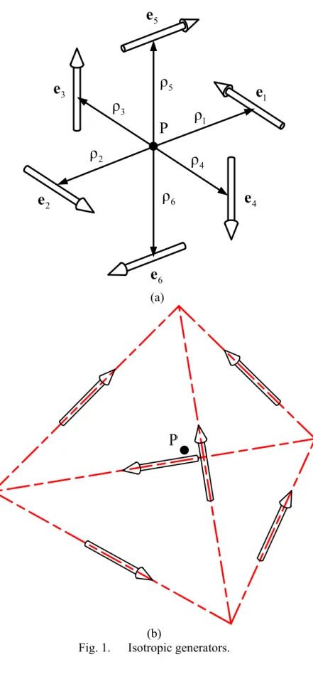
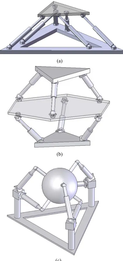
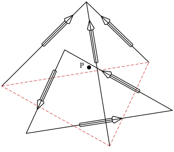
straight line. Then an isotropic generator can be obtained if matrix H satisfies the three isotropy conditions. Figure 1 shows two special generators that have been utilized to develop isotropic serial manipulators, redundant manipulators, or parallel manipulators with different shapes or different types of kinematic chains. The first and second designs in Fig. 2 are developed from the first generator. The two isotropic designs are obtained by placing the spherical joints at the intersecting points of the six straight lines of the generator with two parallel planes. In the second design, the two planes (representing the two fixed bases) are on
the opposite sides of point P (the TCP), and the platform is in the middle of the two fixed bases.
The design in Fig. 2c is obtained by placing six spherical joints at the midpoints of the six sides of the tetrahedron generator, and the remaining spherical joints are near the three intersecting points in the horizontal plane. The direction of jth prismatic joint is parallel to e . Therefore, j developing isotropic parallel manipulators using isotropic generators is simple and efficient.
However, many practical designs cannot be developed due to the geometric constraint of the existing isotropic generators. For example, the six spherical joints on the platform (or base) of the first design cannot be placed on a circle, and the TCP of the two remaining designs can only be at the geometric center of the platform. This section employs numerical methods to develop some new generators (that are not subject to the constraint) and studies their characteristics.
According to the obtained results, we present some special patterns of six straight lines that can be employed to develop much more generators.
The isotropic generators to be studied are obtained by a numerical method in which the relative data of redundant generators are used as the initial values to develop general 6-DOF generators. Redundant 6k or 6k+3 degree-of-freedom generators can be developed from existing special 6-DOF generators.17 In the numerical method, the Plucker&& coordinates of the ith straight line of a generator are expressed as functions of five variables
t
j j j j j j j j
cα βs sα βs cβ x y z
⎡ ⎤
= ⎣ ⎦
$j (2)
where angles αi andβi (the first two angles of Z-Y-Z Euler’s angles) define the direction of unit vector e , andj x y z represent the i, ,i i moment ρ e of the straight line. The j× j variables are subject to the constraint:
j j j j j j j j
x cα βs +y sα βs +z cβ = 0. Let
6 n×
M denote the matrix consisting of
the Plucker&& coordinates of the straight lines of an n-DOF generator. Then the steps involved in developing a 6-DOF generator from an n-DOF generator can be summarized as follows:
1. Obtain M6 n× with n = 6k or 6k+3.
2. Delete an arbitrary column fromM6 n× . Let n = n-1.
3. Determine α βj, j, , ,x y zj j j associated with the remaining columns and use them as the initial values to solve a system of nonlinear equations to obtain an n-DOF generator.
4. Exit if n = 6; otherwise go back to Step 2.
The residues of the nonlinear equations (developed from the isotropy conditions and the related constraints) with α βj, j, , ,x y zj j j as the initial values are very small, so the solutions can be easily obtained. Many new 6-DOF generators are developed using this approach. From the obtained results, we find that the six straight lines of the obtained generators can be divided into two sets of three straight lines, denoted as ( L , L ,L ) and (1 2 3 L , L ,L ), with similar 4 5 6 characteristics. Let d denote the distance from i point P to the ith straight line. Then the obtained generators satisfy the following two conditions:
1. • = • = •
= • = • = •
1 2 2 3 1 3
4 5 5 6 4 6
e e e e e e
e e e e e e (3) 2. d1=d2 = and d3 d4 =d5 = (4) d6 From the second condition, we can conclude that the new generators are different from those obtained by existing analytical methods.
3. DESIGN PARAMETERS AND THE OBJECTIVE FUNCTION
This section utilizes the two conditions in Eqs.
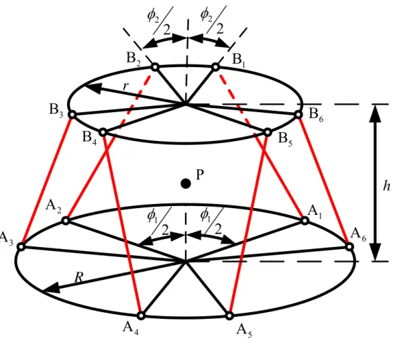
(3) and (4) to propose a special pattern of six straight lines for developing new isotropic generators. Figure 3 shows that the four circles in three horizontal planes with three points on each circle are 120o apart. Let L be the i straight line through points A andi B . Then i
the relative positions of the six straight lines L i (for i = 1, 2,…, 6) satisfy
• = • = • ,
1 2 2 3 1 3
e e e e e e e4•e5 = e5•e6 = e4•e6 , and the second condition in Eq. (4). With point P as the reference point and ρ =j PA , matrix H j can be expressed as functions of r r1, ,2 r r 3, ,4
2, ,3
θ θ θ4,h ,3 h , and the z-coordinate of point P. 4 For 6-DOF manipulators, the closeness to kinematic isotropy can be evaluated by a previously proposed normalized isotropy measure:20
1 3 3 3
1 1
o p
o p
σ σ μ σ σ
⎛ ⎞
=⎜⎜⎝ ∗ ∗Φ⎟⎟⎠ (5) with
2 3 1
1 2 ⎟
⎠
⎜ ⎞
⎝
⎛ +
−
=
Φ σ σ
where
3
σp ,σp1 smallest and largest singular values, respectively, of the 3×6submatrix Hp consisting of the first three rows of H
3
σo , σo1 smallest and largest singular values, respectively, of the 3×6submatrix Ho consisting of the last three rows of H
σ3, σ1 smallest and largest singular values, respectively, of H H% % in which p to H% and p H% o are the two matrices with orthonormal row vectors that span the same row spaces of Hp and Ho respectively
This measure is independent of size and physical units. Conditions 3
1 p
p
σ σ = 1, 3
1 o
o
σ σ = 1, and Φ = 1 (σ3 = σ1 = 0, which indicates that the two subspaces spanned by the row vectors of Hp and Ho, respectively, are orthogonal) are equivalent to the three isotropy conditions. The measure (which yields the optimum value of μ = 1 for an isotropic configuration) will be used as the objective function to develop isotropic generators.
4. ISOTROPIC GENERATORS
This section employs optimization methods to obtain new isotropic generators and utilizes them to develop some special 6-DOF isotropic parallel manipulators with SPS chains.
4.1 Generators with h3∗ > 0 h4
Many general isotropic Stewart-Gough parallel manipulators can be developed using isotropic generators. This section focuses on some special manipulators whose platform and base are represented by two planes, and the spherical joints are placed around a circle on each plane.
In this case, an isotropic design can be obtained by placing the spherical joints at A andi B , and i connecting them with the direction of each prismatic joint parallel to the related straight line for i = 1, 2, …, 6. The desired generators can be developed by letting R =r = r , r =1 2 r = r , 3 4 and h = h = 3 h . 4
Measure μ is independent of size and physical units, so some geometric constraints are needed to avoid obtaining many equivalent generators of different sizes. In this work, we fix the volume V (which represents the size of a manipulator) and the height h of the frustum of a right circular cone. In this case, radii R and r can be related as
( 2 2 2)12
r 1 12 h V 3 h R h R
2 h π π π
π ⎡ ⎤
= ⎢⎣ − − ⎥⎦ (6)
With V = 10000 and h = 10, we provide P z (the z-coordinate of point P) to optimize objective function μ , and some of the optimization results are listed in Table 1.
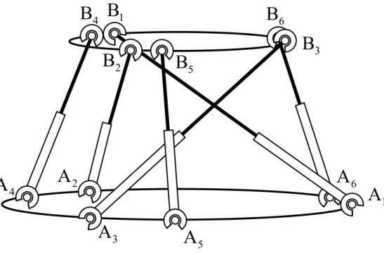
Figure 4 shows the isotropic design with P = z 15. The obtained manipulator, however, is not symmetric and is subject to link interactions.
Figure 5 shows a different pattern of straight lines for developing symmetric manipulators, where anglesφ1 and φ2 satisfy φ φ1+ 2 =120o. Many practical designs can be developed from
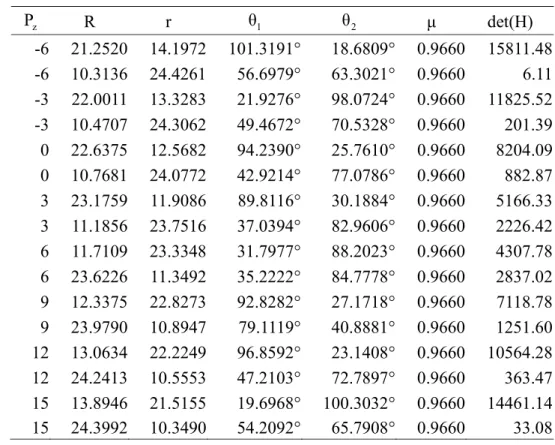
this pattern, but the optimum value of μ cannot reach unity. For a givenP , more than z one generators can be developed by optimization methods. In general, we can obtain one generator with r < R and one generator with r > R. A manipulator is equidistant from its neighboring singular points in an isotropic configuration, but the distance could be very small. For manipulators with equivalent sizes, the distance can be evaluated by the determinant of matrix H, and we prefer the design with a larger determinant. Some of the optimization results (with V = 10000 and h = 10) are provided in Table 2. Figure 6 shows the design with P = 15 and r < R. z
4.2 Generators with h3∗ < 0 h4
Special isotropic generators with R=r = r are 1 2 investigated. The generators can be employed to develop isotropic manipulators similar to the one shown in Fig. 2b. In theory, the manipulators can be developed using generators with h3∗ > 0. An isotropic design can be h4 developed by obtaining the three intersection points of straight lines AiBi for i = 1, 2, 3 (or 4, 5, 6) with a horizontal plane on the opposite side of the x-y plane and moving Bi to the corresponding intersection points. However, we cannot specify radii r and 3 r (of the two 4 circles on the opposite side of the x-y plane) using this approach. With h3∗ < 0 as the h4 constraint, an isotropic generator can be developed by providing P , R, z r , and 3 r . 4 Figure 7 shows an isotropic design with P = 2, z R = 10, r = 3 r = 5. A new isotropic design 4 with different h (or 3 h ) can be obtained by 4 finding three intersection points of the associated three straight lines with a new horizontal plane at different h (or 3 h ) and 4 moving Bi to the corresponding intersection points. The related r (or3 r ) will change in this 4
case.
4.3 Generators with h3 > and 0 h = 0 4
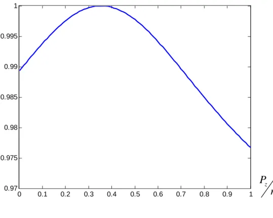
For h = 0, we can provide4 P and z r to develop 1 generators with three straight lines in a horizontal plane. The optimum values of μ for different ratios of z
1
P r are shown in Fig. 8. The closer z
1
P r is to 2
4 , the more μ are close to unity. Many generators can be developed fromPz 2r1
= 4 . The three straight lines that are not in the horizontal plane intersect at one point on the z-axis for generators withPz 2r1
= 4 . One of the generators is equivalent to the tetrahedron generator shown in Fig. 1b, and other generators can be developed by rotating the equilateral triangle in the horizontal plane (of the tetrahedron generator) about the z-axis by an angleθ. The generator with θ =60o is shown Fig. 9.
5. ISOTROPIC MANIPULATORS WITH PSS OR PRRS CHAINS
For the 6-DOF parallel manipulators with PSS or PRRS chains, the external wrench acting on the TCP can be related to actuator forces by
1 1 2
6
τ τ
τ
⎡ • ⎤
⎢ • ⎥
⎡ ⎤= ⎢ ⎥≡ ′
⎢ ⎥ ⎢ ⎥
⎣ ⎦ ⎢⎣ • ⎥⎦
1
2 2
6 6
u e u e
F H Hτ
C
u e
M (7) where
F, C resultant force and resultant moment, respectively, acting on the TCP.
u unit vector defining the direction of the jj th
prismatic joint.
τj jth actuator force.
The jth column of H (defined in Eq. (1)) represents the unit screw that is reciprocal to all the passive screws on the jth chain, and e j
defines the direction of the reciprocal screw. If
• 1
e u = 1 e2•u =…..= 2 e u = 6• 6 λ ≠ 0, then Eq. (7) can be rearranged as
⎡ ⎤=λ ≡ ′
⎢ ⎥⎣ ⎦
F H τ H τ
C (8) where τ denotes the vector of actuator forces. If H satisfies the isotropy conditions, then ′H also satisfies the conditions. Therefore, a 6-DOF isotropic parallel manipulator can be obtained if :(i) the TCP is at point P of a generator; (ii) the six straight lines associated with the six reciprocal screws are coincident with straight linesA B for i = 1, 2,.., 6 of the generator; and i i (iii) e u yields the same non-zero value for j j• j
= 1, 2,.., 6.
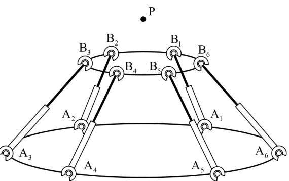
For Stewart-Gough manipulators, s u = 1 i• i for i = 1, 2,.., 6, so an isotropic design can be obtained by placing the tool center point at point P, and the two spherical joints of chain i on A i and B . A PSS chain with i e u = 1 is i• i equivalent to an SPS chain. Therefore, an isotropic design with PSS chains can be developed from an isotropic Stewart-Gough manipulator by replacing the SPS chains with PSS chains (with e u = 1 for i = 1, 2,.., 6). i• i Figure 10 shows an isotropic manipulator with six PSS chains developed from the design in Fig.
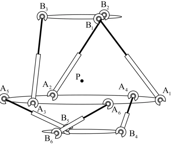
2c. A PRRS chain with twist angles α α1= 2= 0 has the property of e u =1, so an SPS chain i• i can also be replaced by a PRRS chain. Figure 11 shows another isotropic design developed from the design in Fig. 2c by replacing three SPS chains with three PRRS chains. The direction of each prismatic joint on a PRRS chain is parallel to the direction of the related straight line.
Isotropic manipulators with six PSS chains and e ui• ≠i 1 can be developed by choosing u through point i B such that vectors i u and i
i i
B A have the same angle between them for i = 1, 2,.., 6. However, only fractions of the actuator
joint rates/forces are transmitted to the mobile platform because e ui• ≠i 1. Higher degree of resolution for fine position and force control can be obtained for a smaller e ui• i , but smallere u also indicates that a manipulator i• i is closer to inverse kinematic singularity. Some practical designs require special alignments of the prismatic joints. For example, the six prismatic axes of a Hexaglide type manipulator are placed along three straight lines in a horizontal plane. Additional constraints can be added to obtain practical designs. Figure 12a shows a generator developed from h3= = 10 h4 with constraints e u1• 1 = e u2• 2 =…..=
6• 6
e u , where i i+3
i i+3
B B
= = B B
i i+3
u u for i = 1, 2, 3. An isotropic design (with e u = 0.8165 j• j for j = 1, 2,.., 6) developed from the generator is shown in Fig. 12b. Other isotropic parallel manipulators with different shapes or different types of kinematic chains can be developed using similar approaches.
6. CONCLUSION
This work presented methods for developing new isotropic generators. Some properties of isotropic generators were obtained and utilized to propose two special patterns of six straight lines. Many new generators were developed using the related data of the straight lines as the initial values in optimization methods. The obtained generators were employed to develop parallel manipulators with different shapes and different types of kinematic chains. In the future, the proposed methods can be extended to develop other classes of isotropic generators, or we can search for the isotropic design with optimum global dexterity.
Acknowledgments
This research work is supported by the National Science Council of the Republic of China under grant NSC96-2212-E011-110.
References
1. C. M. Gosselin and J. Angeles, The optimum kinematic design of a planar three-degree-of freedom manipulator, J Mech Trans Automat in Design, 110 (1988), pp. 35-41.
2. C. M. Gosselin and J. Angeles, The optimum kinematic design of a spherical three-degree-of freedom manipulator, J Mech Trans Automat in Design, 111 (1989), pp. 202-207.
3. J. Angeles and Lopez-Cajun, C. S, Kinematic isotropy and the conditioning index of serial robotic manipulators, Int. J.
Robot. Res., 11:(6) (1992), pp.560-571.
4. M. Kircanski, “Kinematic isotropy and optimal kinematic design of planar manipulators and a 3-DOF spatial manipulator,” Int J Robot Res., 15:(1) (1996), pp. 61-77.
5. K. H. Pittens, R. P. Podhorodeski, A family of Stewart platforms with optimal dexterity, J. of Robot. Sys., 10:(4) (1993), pp. 463-479.
6. R. S. Stoughton, T. Arai, A modified Stewart platform manipulator with improved dexterity, IEEE Transactions on Robotics and Automation 9:(2) (1993), pp. 166-173.
7. S. Bhattacharya, H. Hatwal, and A. Ghosh, On the optimum design of Stewart platform type parallel manipulators, Robotica, 13:(2) (1995), pp. 133-140.
8. Lee, J., J. Duffy, and K.H. Hunt, Practical quality index on the octahedral manipulator,” Int. J. Robot. Res., 17:(10) (1998), pp.1081-1090.
9. W. A. Khan, J. Angeles, The kinetostatic optimization of robotic manipulators: the inverse and the direct problems, ASME J.
Mech. Des., 128:(1) (2006), pp. 168-178.
10. J. Angeles, The design of isotropic
manipulator architectures in the presence of redundancies, Int. J. Robot. Res., 11:(3) (1992), pp.196-201.
11. J. Angeles, Fundamentals of robotic mechanical systems, Springer, New York, 2002.
12. K. E. Zanganeh and J. Angeles, Kinematic isotropy and the optimum design of parallel manipulators, Int. J. Robot. Res., 16:(2) (1997), pp.185-197.
13. A. Fattah, A. M. H. Ghasemi, Isotropic design of spatial parallel manipulators, Int. J.
Robot. Res., 21:(9) (2002) 811-824.
14. I. Fassi, G.. Legnani and D. Tosi, Geometrical conditions for the design of partial or full isotropic hexapods, J. of Robot.
Sys., 22:(10) (2005), pp. 507-518.
15. C. A. Klein and T. A. Miklos, Spatial robotic isotropy, Int. J. Robot. Res., 10:(4) (1991), pp. 426-437.
16. K. Y. Tsai and K. D. Huang, The design of isotropic 6-DOF parallel manipulators using isotropy generators, Mech. and Mach.
Theory, 38:(11) (2003), pp. 1199-1214.
17. K. Y. Tsai and Z. W. Wang, The design of redundant isotropic manipulators with special parameters, Robotica, 23(2005), pp.
231-237.
18. K. Y. Tsai and T. K. Lee, 6-DOF isotropic parallel manipulator with three PPSR or PRPS chains, 12th IFToMM Conference, Besancon (France), June 18-21, 2007.
19. K. Y. Tsai and T. K. Lee, 6-DOF parallel manipulators with better dexterity, rotatability or singularity-free workspace, submitted to Robotica.
20. K. Y. Tsai and S. R. Zhou, The optimum design of 6-DOF isotropic parallel Manipulators, J. of Robot. Sys., 22:(6) (2005), pp. 333-340.
Table 1. Related data of isotropic generators.
P z R r θ 2 θ 3 θ 4 μ
-6 13.5343 21.8256 -8.6370° 122.7523° -16.4399° 0.9943 -3 13.5343 21.8256 -27.3612° 7.1363° -154.3250° 0.9998 0 13.5330 21.8267 172.4301° 125.2982° 165.0647° 0.9975 3 13.5344 21.8256 37.5444° -8.5636° 155.6913° 0.9894 6 21.8233 13.5370 128.6413° 9.1850° 13.9310° 0.9862 9 21.8251 13.5349 -120.2600° -7.6919° 3.2630° 0.9952 12 21.8438 13.5130 -141.2876° -126.6289° -134.6234° 0.9998 15 21.8258 13.5341 149.3013° 124.7730° 141.8242° 0.9968
Table 2. Related data of symmetric generators.
P z R r θ 1 θ 2 μ det(H)
-6 21.2520 14.1972 101.3191° 18.6809° 0.9660 15811.48 -6 10.3136 24.4261 56.6979° 63.3021° 0.9660 6.11 -3 22.0011 13.3283 21.9276° 98.0724° 0.9660 11825.52 -3 10.4707 24.3062 49.4672° 70.5328° 0.9660 201.39 0 22.6375 12.5682 94.2390° 25.7610° 0.9660 8204.09 0 10.7681 24.0772 42.9214° 77.0786° 0.9660 882.87 3 23.1759 11.9086 89.8116° 30.1884° 0.9660 5166.33 3 11.1856 23.7516 37.0394° 82.9606° 0.9660 2226.42 6 11.7109 23.3348 31.7977° 88.2023° 0.9660 4307.78 6 23.6226 11.3492 35.2222° 84.7778° 0.9660 2837.02 9 12.3375 22.8273 92.8282° 27.1718° 0.9660 7118.78 9 23.9790 10.8947 79.1119° 40.8881° 0.9660 1251.60 12 13.0634 22.2249 96.8592° 23.1408° 0.9660 10564.28 12 24.2413 10.5553 47.2103° 72.7897° 0.9660 363.47 15 13.8946 21.5155 19.6968° 100.3032° 0.9660 14461.14 15 24.3992 10.3490 54.2092° 65.7908° 0.9660 33.08
e1
e2
P e3
e4
e5
e6
ρ6
ρ5
ρ4
ρ3
ρ1
ρ2
(a)
(b)
Fig. 1. Isotropic generators.
(a)
(b)
(c)
Fig. 2. Isotropic parallel manipulators with different shapes.
X Z
Y
r1 r2
r3
r4
h3
h4
θ2
θ3
θ4
P
A2
A3
A1
A4
A5
A6
B1
B2
B3
B4
B5
B6
Fig. 3. Parameters for developing isotropic generators.
A2
A3
A1
A4
A5
A6
B1
B2 B3
B4
B5
B6
P
Fig. 4. A 6-DOF isotropic parallel manipulator.
r
R
P h A2
A3
A1
A4 A5
A6
B1
B2
B3
B4 B5
B6 22
φ
12
φ 1
φ 2
2 2 φ
Fig. 5. Parameters for developing symmetric isotropic generators.
P B1
B2
B3 B6
B5
B4
A2
A3
A1
A4 A5 6
A
Fig. 6. A symmetric 6-DOF parallel manipulator.
B4
B5
B6
A2
A3
A1
A4
A5
A6
B1
B2
B3
P
Fig. 7. An isotropic design with the platform in the middle of two fixed bases.
1
Pz
r μ
0 0.1 0.2 0.3 0.4 0.5 0.6 0.7 0.8 0.9 1
0.97 0.975 0.98 0.985 0.99 0.995 1
Fig. 8. Optimum values of μ for different ratios of z
1
P r .
P
Fig. 9. An isotropic generator with three straight lines in a horizontal plane.
Fig. 10. An isotropic parallel manipulator with six PSS kinematic chains.
Fig. 11. An isotropic parallel manipulator with different types of kinematic chains.
P
6 3 A
5 A
2 A A
4 1 A A
B1
B2
B3
B5
B4
B6
(a)
(b)
Fig. 12. A Hexaglide type isotropic manipulator.
計畫成果自評:
此 成 果 已 寫 成 論 文 “A new class of isotropic generators for developing 6-DOF isotropic manipulators” 投稿至 Robotica 目前已被接受並 published on line.
國立台灣科技大學 機械工程系
計畫名稱:滑軌式具複合鏈六自由度等向性並聯式機器人之設計,分析及製作
主持人:蔡高岳 副教授
主旨:德國紐倫堡國際發明競賽參賽報告
參賽時間:2007 年 11 月 1 日至 2007 年 11 月 4 日
參賽作品:一種具切換模式之多功能訂書機
專利名稱:一種具切換模式之多功能訂書機及其切換方式
專利申請日:096114072
申請日期:民國 96 年 4 月 20 日
參展過程與心得:
10 月 30 日晚上 10 點從桃園中正機場出發,我們兩個從來沒有做過飛機,
心裡真是既期待又興奮,不過要到德國需要花上 13 個小時的時間,這麼漫長的
時間讓我們感到有些許的疲倦,只好閉目養神,想一想到時參展的時候要如何用
英語跟外國人溝通。
到德國法蘭克福機場後還要大約 3 個小時的車程才會到紐倫堡,整個團隊會
先到會場布置攤位,當我們看到會場時,規模之大讓我們大開眼界,雖然在 9
個會場,每個會場都有不同的參展主題,可以在多餘的時間參觀。在布置的時候
也看到我國許多的傑出發明家,有些還只是國中生而已,有的是老師、教授或是
社會人士、公司大老闆,甚至還遇到在工研院工作的學長,還有中山女中的校長,
甚麼人物都有,要能認識這些人大概也只有在這種機會才有可能遇到。
隔天正式開始參展,但是時差很難調整,真的很疲累,還好第一天參展的人
不會很多,所以比較輕鬆些。參展第二天,我們養足精神,很熱情的跟外國人介
紹我們的發明,當然有些人會認為我們的發明不實用,也會給我們一些很好建議,
有些人會覺得這是一件很棒的發明,每個人的感覺不同,這就好像在做市場調查
一樣,蒐集這些資訊可以了解市場的需求,可以對我們所設計的產品做些改良,
真是收穫良多。
參展第三天是最重要的一天,不能擅自離開攤位,因為大會評審會來評分,
有的評審不會主動表明身分,夾雜在參展的人群當中,所以很難知道誰是評審,
所以對每個來到攤位參觀的人,我們都很認真的解說我們所設計的發明,當然這
天也會有需多買家來找尋他們中意的發明,只要看上了就會提出價錢買專利,很
可惜我們的發明沒有這樣的機會,或許是在歐洲沒有這樣的式場要求吧。到了晚
上更是令人期待,所有的努力就看今晚了,因為那頒獎典禮的時刻,投影機投射
到布幕上,得獎名單就在那,主要分成四大類別,由於我們在學中,所以被分類
為青少年組,到了青少年組的得獎名單時,我們仔細聆聽並專注的看著投影幕上
會連個銅牌獎都沒有吧,過了些許時間突然有人叫我們上去頒獎,一時之間還沒
回神就上台了,當獎牌交到手上時才知道我們得了銀牌獎,那時真是高興致極了,
頒獎結束時,團長帶團慶功宴,大吃大喝慶祝一番。
參展第四天,人潮相當地多,由於前三天我們都固守攤位,沒辦法參觀別國
家的發明產品及別會場的展覽,因此我們輪流守攤位,到處去參觀拍照留念,當
然在此發明會場裡不能拍照的,所以就到外面拍拍會館的風貌或是附近的風景,
留做紀念。
結束這四天的展覽後,又到德國許多大城參訪,見識到德國不僅保有自己的
民俗文化,更創造出驚人的工業技術,期待台灣有一天也能擁有世界頂尖工業技
術的能力。
在參展時,有很多新奇古怪的發明,甚至會看到以前曾經想設計的東西,看
到別人的解決方法,對於我們的設計觀念有許多啟發,也深刻的體會到開發產品
時間的重要性,為提升自身的競爭力,應放眼國際,儼然現在的社會環境已成為
國際村,我們的競爭者遍部全球,若台灣團結起來,一定能共同打造美好的未來。
實體照片
參賽結果
獲得時的那一刻
得獎證明