Journal of Engineering Technology and Education, ISSN 1813-3851
Study on Optimization for Four Bar-Partially Compliant Mechanism
Shyh-Chour Huang*, Thanh-Phong DaoDepartment of Mechanical Engineering,
National Kaohsiung University of Applied Sciences Kaohsiung, Taiwan *E-mail: [email protected]
Abstract
This paper concentrates on the application of fuzzy logic based on Taguchi method (FLTM) for multiobjective optimization of the small-length flexural pivot (belongs to link 4) in partially four bar-compliant mechanisms. The input parameters such as the input torque and the crank angle of link 2 were optimized with considerations of the multiple performance measures as angular displacement and stress of the small-length flexural pivot. Angular displacement and stress of the small-length flexural pivot are two objective functions were formulated using pseudo-rigid-body model (PRBM) and principle of virtual work. The results found that the input torque at level 1 of 3 Nm and crank angular at level 1 of 100 degrees are favorable parameters for compliant flapper mechanism. Based on ANOVA, the results showed that input torque is the most significant with respond highest value of F test of 4.1752.
Keywords: Multi-response performance index, Fuzzy logic based on Taguchi method, Pseudo-rigid-body model
1. Introduction
Design and analysis of compliant mechanisms have interested in past decades due to their less expensive, lighter as compared to rigid-link mechanisms. The compliant mechanisms relies on the deflection of flexible members, thus their maximum deflection and minimum stress have been the important issues in designing flexible structures in recent years. In 2010, Tanık et al. [1] used the theory of the pseudo-rigid-body model (PRBM) to analyze compliant variable stroke mechanism. Khatait et al. [2] modified the stiffness of the flexural hinges to minimize driving torque. Midha et al. [3] utilized PRBM to analyze limit positions of compliant mechanism. Dado [4] studied large deflections of compliant mechanism using PRBM. In 2012, Hsiang et al. [5] studied the optimization of extrusion magnesium alloy bicycle carriers by using fuzzy logic based on Taguchi method (FLTM). According to Venanzi [6], the non-linear position analysis of planar compliant mechanisms was performed by using an iterative technique. A new method is proposed to easily establish simple and analyze using PRBM for a variety of beam-based compliant mechanisms performed by Pei [7]. The other study by Tsay [8] presented the design, fabrication and experiment of fully compliant bistable micro-mechanisms. Pucheta [9] presented a method is based on the solution of the initial and final unstrained positions for the design of bistable mechanisms. In 2011, Gupta et al. [10] presented the application of FLTM for multiple output optimization of high speed CNC turning.
In spite of the four-bar compliant mechanisms have been so far received a growth of interest in the robotic devices and the other growth of specific interest to humanoid robots where human-like manipulation skill is required as well because their size, weight, reliability, cost and applicability, etc. In order to analyze kinematics, dynamics, and optimize these compliant mechanisms, they have still been the complicated problems to researchers. In particular, the structure of the compliant mechanisms is very sensitive to dynamic actions like shock and
vibrations that occur during motion process. In order to move to desired positions the fatigue, the stress, and thus the displacement must be considered in design area simultaneously.
One of the challenges of compliant mechanism is to allow large enough deflections for the mechanism to perform its function while maintaining stresses below an allowable maximum stress. Therefore, the maximum displacement and minimum stress have been still interested tasks in recent years for many researchers. There are many optimization approaches used in engineering such as Taguchi method, fuzzy logic control, genetic algorithm, and neural network; among them, Taguchi method is not a complicate procedure but it can only optimize for single objective function. As a result, an attempt to develop approaches for optimization of multi-objective functions has researched so far, like FLTM, genetic algorithm based on fuzzy logic control, etc. One of the another reasons is that almost previous studies have not significantly investigated the optimization compliant mechanisms by using FLTM; they focused on the use of conventional procedures to optimize topology of mechanisms and more recently years some authors have optimized the various shapes of flexible segments to release the stress concentration along the flexible beams. As a result, the optimization of process parameters to maximize deflection of flexible segment and minimize its stress simultaneously was studied in this paper.
There have been many existed effective approaches such as the PRBM, the screw theory, the building-block based approach, the topological optimization, and the constraint-based design to analyze statics, kinematics and dynamics of the compliant mechanisms. Among them, the PRBM is a helpful tool and easy to use. So, the PRBM was applied in this paper.
In addition, the equations of multiobjective functions are formulated by using PRBM and the principle of virtual work; these have been easy tools to analyze the compliant mechanisms in past decades. In fuzzy-logic control algorithm, the membership functions setting is very important in order to achieve optimal parameter value, there are excessive number of experiments; therefore, this research exploited Taguchi method was adopted to decrease the number of experiments. Furthermore, the adjusting the weight of membership function is also significantly important to achieve optimal system.
This paper describes the main guidelines for analysis and optimization of four-bar partially compliant mechanism. It proposes a novel optimization method that is FLTM in order to maximize angular displacement and minimize stress simultaneously of small-length flexural pivot. This one can further uses in the other structures and engineering fields.
The rest of the paper is organized as follows. Section 2 analyzes four-bar partially compliant mechanism in order to formulate the multi-objective function equations. Section 3 describes the optimization of four-bar partially compliant mechanism. It will present Taguchi method with multiple performance characteristics and the way how to combine with the fuzzy logic controller in the optimization for angular displacement and the stress simultaneously. Also in Section 3, this paper will present the results and discussions of the paper. Final section will be the conclusion of this study.
2. Analysis of Four-Bar Partially Compliant Mechanism
In this stage, the paper will apply theory of PRBM and virtual work [11] to model and analyze flexible beams and segments. And then it will formulate the equations of multiobjective functions including angular displacement and stress for optimal process.
2.1 Modeling
In this paper, the compliant beams are made of polypropylene
(
E =200,000lb/in2)
due to its low density andhigh strength-to-modulus ratio. Polypropylene is ductile material and thus it is much less likely to result in catastrophic failure when yielded. The PRBM [11] was utilized to analyze the deflection and the stress of flexible segment in for-bar partially compliant mechanism. The mathematical models of the deflection and the stress of flexible segment were formulated as the following.
The partially compliant mechanism as shown in Fig. 1 is a four bar mechanism as a case of a Grashof mechanism known as triple couplers with input crank is link 2, remaining links are rockers. A functional binary, fixed-pinned flexible segment is link 3. The output rocker is link 4 that has one small-length flexural pivot. Deflected position gives in Fig. 2a. The PRBM is shown in Fig. 2b. Using Brushless DC Servo Motor to control flapper compliant mechanism with the following specifications (power: 200 to 4,000 Watts, torque: 2Nm to
Nm
115 ). The dimension of links as follows:
- Cross section of rigid links: Width of 0.8inand thickness of 0.2in.
- Ground link: r =1 3.02in. - Input crank: r =2 in.
- The long flexible segment: l =3 2.97in,width b =3 0.5in, thicknessh =3 0.04in.
- The output rocker: Rigid link of 3in,l =4 0.31in,b =4 0.6in,h =4 0.5in.
This study selected constant values of characteristic radius factor, γ=0.85and stiffness coefficient, 67
. 2 = Θ
K [11] result in a pseudo-rigid coupler with length r3=γl3=2.53in, r4=
(
2.91+l4/2)
=3.07in.The moments of inertial of the flexible segments are:
12 3 3 3 3 bh I = (1) 12 3 4 4 4 bh I = (2)
The flexible segments always remains initial state where 0 2=90
θ . The values of θ and 30 θ40can be calculated
by using the closed-form equations [11] as follows: The crank angle measured from
r
1isθ2′ :1 2 2 θ θ
θ′= + (3)
whereθ is the angle between horizontal direction with the line coupled from joint A to joint D. 1
The law of cosines may be used to determine the length of δ and the internal anglesβand
λ
as follows:(
)
1/2 2 2 1 2 2 2 1 2 cosθ
δ
= r +r − rr ′ (4) δ δ β 1 2 2 2 2 1 2 cos r r r a + − = (5)δ δ λ 4 2 3 2 2 4 2 cos r r r a + − = (6) δ δ α 3 2 4 2 2 3 2 cos r r r + − = (7)
Two possible values exist for each angle for a given θ The link angles are calculated as follows: 2.
For 0≤θ2′≤π
(
1)
3α
β
θ
θ
= − − (8)(
1)
4π
λ
β
θ
θ
= − − − (9) For π≤θ2′≤2π(
1)
3α
β
θ
θ
= + + (10)(
1)
4π
λ
β
θ
θ
= − + + (11)Fig. 2 a. Deflected position model, b. Pseudo-rigid body model 2.2 Reaction Forces at Pivot joints
Free body diagrams (Newtonian methods) [11] are used to determine equations of reaction forces at pivots for static equilibrium of each link. Free body diagrams of links are illustrated in Fig. 3.
Fig. 3 Free body diagram of links: a. Link 2, b. Link 3, c. Link 4 For link 2: 0 32 12x+F x = F (12) 0 32 12y +F y = F (13)
(
90)
cos(
90)
0 sin 2 32 2 2 2 32 × × − − × × − = −F rθ
F rθ
Tin y x (14) For link 3:0 43 23x +F x = F (15) 0 43 23y +F y = F (16) 0 sin cos 3 43 3 3 3 43 43+F ×r × θ −F ×r × θ = T y x (17) For link 4: 0 34 14x+F x = F (18) 0 34 14y+F y = F (19)
(
90)
cos(
90)
0 sin 4 34 4 4 4 34 34 14+T −F ×r × θ − −F ×r × θ − = T y x (20)At a pin joint, the forces on the connected links have equal magnitude but are in opposite directions: x x F F23 =− 32 (21) y y F F23 =− 32 (22) x x F F34 =− 43 (23) y y F F34 =− 43 (24)
The spring constants at pin joints due to the springs [11]: Due to fixed-pinned segment
3 34 = l EI K K γ Θ (25)
Due small-length flexural pivot
4 14 = l EI K (26)
The torques at pin joints due the as follows [11]: A PRBM with a linear torsional spring constant, Ki,
i i
K
T=− Ψ (27)
where Ψ is the Largrangian coordinate The torque at pin joints 1 and 2:
0
2 1
=
T
=
T
(28)The torque caused by the torsional spring modeling fixed-pinned segment:
(
) (
)
[
4 40 3 30]
3 3 34 34γ
θ
−θ
−θ
−θ
− = Ψ − = Θ l EI K K T (29)The torque caused by the torsional spring modeling the small-length flexural pivot:
(
)
(
4 40)
4 40 4 4 14 14Ψ
θ
θ
θ
−θ
− = − = − = l EI K T (30)Combining Eqs.15, 16, and 17 results in:
0
sin
cos
3 23 3 3 3 23 43−
F
×
r
×
θ
+
F
×
r
×
θ
=
T
y x (31)Combining Eqs.14, 21, and 22 results in:
(
90)
cos(
90)
0 sin 2 23 2 2 2 23 × × − + × × − = +F rθ
F rθ
Tin y x (32)From Eq.31 results in:
3 3 43 3 23 23 =F ×cotθ −r ×Tsinθ F x y (33) Substituting Eq.33 into Eq.32 results in:
(
)
(
)
(
)
[
sin 90 cot cos 90]
sin sin 90 cos 2 3 2 3 3 2 3 3 2 2 43 23 × × − + × − × × − − × × = θ θ θ θ θ θ r r r T r T F in y (34)
Substituting Eq.34 into Eq.33 results in
(
)
[
]
[
]
(
)
(
)
[
]
× − − × + − × × × × × − − × × = 3 3 43 2 3 2 3 3 2 3 3 3 2 2 4323 rT r rsincosθ sinθ θ9090T cotrθ sincosθ θcot90θ r Tsinθ
F in
Combining Eqs.17, 23, and 24 results in:
0
sin
cos
3 34 3 3 3 34 43−
F
×
r
×
θ
+
F
×
r
×
θ
=
T
y x (36)From Eq.36 results:
3 3 43 3 34 34 =F ×cotθ −r ×Tsinθ F x y (37)
Substituting Eq.37 into Eq.20 results in:
(
)
(
)
(
)
(
)
[
90 90]
90 4 3 4 3 4 3 4 4 3 3 34 3 334 =Tr ××rr××sinsinθθ sin+Tθ r−×sin+θcot+θr ××coscosθθ −−
F in
y (38)
Substituting Eq.38 into Eq.37 results in:
(
)
(
)
[
]
(
)
(
)
[
]
× − − × + − × × − × + × + × × = 3 3 43 4 3 4 3 4 3 3 4 4 3 3 34 3 334 T rr rsinsinθ θTsinrθ sin90θ cotr θcoscosθ θ9090cotθ r Tsinθ
F in
x (39)
2.3 Angular Displacement of Small-Length Flexural Pivot
Virtual work [11] was used to determine the deflection-force relationship. Based on PRBM and virtual work, the deflection-force relationship for flexible segment was determined.
Degrees of freedom of the mechanism:
(
1)
2 1 23n J J
F= − − − (40)
where
n
is number of links(
n=4)
1
J is lower pair
(
J1=4)
2
J is higher pair
(
J2=0)
Thus, this study calculated degree of freedom isF=1
The minimum number of Lagrangian coordinates required for a complete set is equal to the number of degrees of freedom of system. Because the mechanism has one degree of freedom, it will have one generalized coordinate. Choose θ2 as the generalized coordinate because it is the known input. Considering the system of this mechanism, there is only an input moment T that causes input angular displacement,in δθ2. A torque, T , caused 34
angular displacement, δθ4. Thus, total virtual work of this mechanism is [11]: 2 2 4 2 3 δθ δθ δθ δθ δθ δ + + = A B C w (41) Applying the principle of virtual work (δw=0) results in
0 2 4 2 3 + = + δθ δθ δθ δθ C B A (42) where: in T A = (43)
(
) (
)
[
4 40 3 30]
3 34=γ θ −θ − θ −θ − = Θ l EI K T B (44)(
) (
)
[
]
(
4 40)
4 30 3 40 4 3 14 34 γ θ θ θ θ θ −θ − − − − − = + =T T KΘ EIl EIl C (45)The kinematics coefficients are:
(
)
(
3 4)
3 2 4 2 2 3 sin sin θ θ θ θ δθ δθ − − = r r (46) The angular displacement of the small-length flexural pivot, δθ4, is derived from Eq.45 as follows:C A B 2 2 3 4 δθδθ δθ δθ + − = (47)
Substituting Eqs.42, 43, 44, 45and 46 into Eq.47 results in:
(
) (
)
[
]
(
(
)
)
(
) (
)
[
]
(
)
− + − − − + − − − − − = Θ Θ 40 4 4 30 3 40 4 3 2 4 3 2 2 4 3 30 3 40 4 3 4 sin sin θ θ θ θ θ θ γ δ θ θ θ θ θ θ θ θ γ δθ l EI l EI K T r r l EI K in (48)2.4 Maximum Stress of Small-Length Flexural Pivot
The maximum stress for a cantilever flexible beam occurs at the fixed end. The maximum stress may occur at the top or bottom of the beam, depending on the direction of the force. In this mechanism, a flexible beam has cross-section with the out-of-plane thickness, w and the in-of-plane thickness, h [11] as follows:
(
)
wh np wh npb pa top − + − = 6 2 σ (49)(
)
wh np wh npb pa bot − + =6 2 σ (50)There is no axial force and only has bending forces in this case. Thus, considering stress due bending force.
4 4 0.155 3.07cos cos 2 2 θ = + θ + + =l L l a (51) 4 4 3.07sin sin 2 θ = θ + = L l b (52)
(
)
2 34 34 wh bF aF x y top + − = σ (53)(
)
2 34 34 wh bF aF x y bot + = σ (54)The maximum stress at fixed-end of small-length flexural pivot is
(
)
[
[
(
(
)
(
(
)
)
]
)
]
[
(
(
)
(
(
)
)
)
]
2 4 3 4 3 4 3 4 4 3 3 34 3 3 4 3 3 43 4 3 4 3 4 3 3 4 4 3 3 34 3 34 sinsin sin sin90 cot coscos 9090cot sin .307sin sinsin sin 90sincot coscos 9090 cos 07 .3 155 .0 wh r r r r T r T r T r r r r T r Tin in − × + − × × − × + × + × × + × − − × + − × × − × + × + × × + = θ θ θ θ θ θ θ θ θ θ θ θ θ θ θ θ θ θ σ (55) where
[
(
4 40) (
3 30)
]
3 34 γ θ −θ −θ −θ − = KΘ EIl T , T34 =−T43 (56)The variations in process parameters such as input torque and input crank angular greatly affect the motion perform of the flapper compliant mechanism as angular displacement and stress. Therefore, proper selection of the process parameters can result in better performance in motion of this mechanism.
3. Optimization of Four-Bar Partially Compliant Mechanism
3.1 Formulation of the optimization problemThis study determines the optimal process parameters that influence the structure of four-bar partially compliant mechanism by simultaneous optimizing the maximum angular displacement and minimum stress to obtain optimal motion performance. Therefore, the higher-the-better angular displacement and the lower-the-better stress should be selected. The optimization problem for four-bar partially compliant mechanism is formulated as follows:
(
)
(
) (
)
(
(
)
)
(
) (
)
(
)
3 4 2 2 1 2 4 40 3 30 3 2 3 4 4 40 3 30 4 40 3 4 sin , sin in in r EI f T K T l r K EI EI l l θ θ δ θ γ θ θ θ θ θ θ γ θ θ θ θ θ θ Θ Θ − = − − − − + − − − + − (57)Minimize the maximum stress at fixed end of small-length flexural pivot belongs to link 4:
(
)
(
)
3 3 34 3(
(
)
3 4(
4(
)
)
)
3 43 3 3(
34 3(
)
3 4(
4)
)
4 4 3 3 3 4 3 4 3 4 3 4 3 4 3 2 2sin sin cos 90 cot sin sin cos 90
0.155 3.07cos 3.07sin
sin
sin sin 90 cot cos 90 sin sin 90 cot c , in in in T r T r r T T r T r r r r r r r f T θ θ θ θ θ θ θ θ θ θ θ θ θ θ θ θ θ θ × × + × + × − × × + × + × − + − + × × × − + × − × × − + × = 2 os
(
4 90)
wh θ − (58)subject to the constraints:
2 95 100d 3 eg 180deg in Nm T Nm θ ≤ ≤ ≤ ≤ (59)
Where Tin is a input torque and θ2 is the input rotational angle of link 2 that must determine to satisfy two objective functions; while θ30, θ3, θ40, and θ4 are angles that were calculated in terms of θ2 known.
3.2 Optimal Procedure
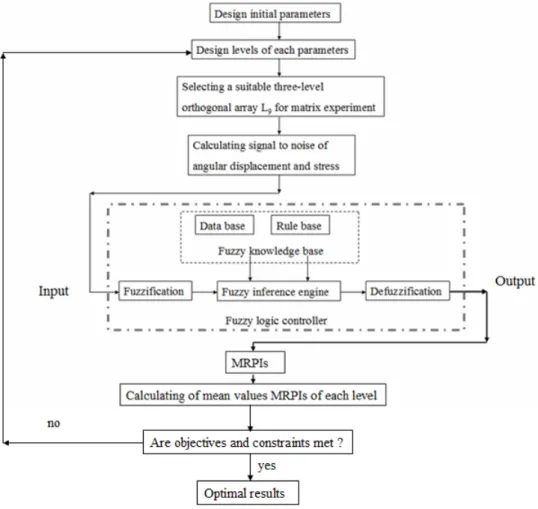
In order to find optimal process parameter values based on a single quality characteristic, the Taguchi method is one of the most significant tools because it is an efficient experimental method, and only requires a small number of experiments to measure the quality and analysis of the optimal process. However, optimal results obtained using different quality characteristics always contradict each other. However, optimal results obtained using different quality characteristics always contradict each other. As a result, in an attempt to improve this contradictory problem, fuzzy logic combined with the Taguchi method (FLTM) was utilized in this paper to find the combination of process parameters that optimize the multi-response performance index (MRPI). The flow chart structure of the fuzzy logic controller coupled with the Taguchi method used in the study is shown in Fig. 4.
Fig. 4 Flow chart of Fuzzy logic controller combined with Taguchi method 3.2.1. Taguchi method
Taguchi method applications are concerned with the optimization of a single performance characteristic. The Taguchi method uses a special design of orthogonal arrays to study an entire parameter space with only a small number of experiments. The experimental results are then transformed into a signal-to-noise (S/N) ratio. The S/N ratio can be used to measure performance characteristics deviating from the desired values. Usually, there are three categories of the performance characteristics in the analysis of the S/N ratio: the lower-the-better, the higher-the-better and the nominal-the-better. In this study, L9 orthogonal array experiment is used with the two right columns are ignored because there are two parameters and their three levels. To obtain optimal motion performance, the maximum angular displacement and the minimum stress are desired. Therefore, the higher-the-better angular displacement and the lower-the-better stress should be selected. After determining the orthogonal array experiment and the number of parameters levels, this research performs calculation for S/N of the angular displacement and the stress of small-flexible segment as the following equations briefly describe: The higher-the-better angular displacement is:
− =
∑
= n i i L n y N S 1 2 1 1 log 10 / (60) − =
∑
= n i i S n y N S 1 2 1 log 10 / (61)where y is the observed data
To consider the two different performance characteristics in the Taguchi method, the S/N ratios corresponding to the angular displacement and the maximum stress at fixed end of flexure hinge are two inputs processed by the fuzzy logic control in order to find out optimal parameter values.
3.2.2 Fuzzy Logic Based on Taguchi Method
Using fuzzy logic control, the optimization of multiple performance characteristics can be transformed into the optimization of a single performance index. Thus, the proposed method is the integration of fuzzy logic control with the Taguchi method; they are used to simultaneously achieve the optimization of multiple performance characteristics.
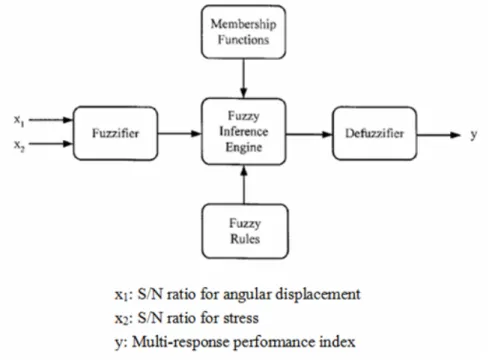
A fuzzy logic unit comprises a fuzzifier, membership functions, a fuzzy rule base, an inference engine and a defuzzifier. First, the fuzzifier uses member functions to fuzzify the signal-to-noise ratios. Next, the inference engine performs fuzzy reasoning on fuzzy rules to generate a fuzzy value. Finally, the defuzzifier converts the fuzzy value into a multi-response performance index. The structure of the two-input-one-output fuzzy logic is shown in Figure 5. In the following, the concept of fuzzy reasoning is briefly described, based on the two-input-one-output fuzzy logic unit. The fuzzy rule base consists of a group of if-then control rules, with two inputs, x1 and x2, and one output, y.
Fig. 5 Structure of the two-input-one-output fuzzy logic control
An orthogonal array, the S/N ratio and MRPI are used to study the performance characteristics of this mechanism. Matlab 7.1 software is used to solve the roots of nonlinear equations and support for fuzzy logic.
Regardless of the category of the performance characteristic, a larger S/N ratio corresponds to a better performance characteristic. As a result, the optimal level of the process parameters is the level with the highest S/N ratio. The loss function corresponding to each performance characteristic is fuzzified; then an MRPI is achieved through fuzzy reasoning using fuzzy rules.
3.3. Results and Discussions
According to the flow chat structure in Fig.4 an optimal process for for-bar partially compliant mechanism is performed using FLTM. This research formulated nine fuzzy rules in Table 1 that are directly based on the fact that the larger the S/N ratio is, the better the performance characteristic in fuzzy logic controller as presented.
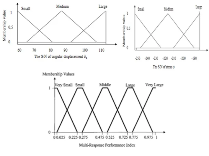
There are two input process parameters in this research such as input torque and crank angular. The value of input torque A has the range from 3 to 95Nm, while the value of crank angle B has the range from 100 to 180 degrees; and the value of each of these process parameters was divided into three levels as shown in Table 2. Based on Taguchi method, the L9 orthogonal array with nine experiments and detailed values of each level was given in Table 3. The higher-the-better angular displacement and the lower-the-better stress should be selected in this study. After that, the membership functions were created by using Matlab software as presented in Fig. 6. The membership function of the S/N ratio for the stress has the range from 0 to 1 and the membership function of the S/N ratio of angular displacement also has the range from 0 to 1. The membership functions can be adjusted to find real optimal parameters value. These membership functions are triangle shapes. Meanwhile, the membership functions of MRPI have trapezoidal shapes and the range from 0 to 1. Figure 6 also presents the range of the S/N ratio for the angular displacement from 60 to 110, the range of S/N ratio of the stress from -250 to -190, and the range of MRPI from 0 to 1. The results of the S/N ratio for the stress, S/N ratio of angular displacement, and the MRPI were calculated in Table 4. Next, the mean of MRPI of input torque A and crank angle B at each of their levels was calculated in Table 5. The larger the MRPI is, the smaller the variance of performance characteristics around the desired value. Based on Fig.7, the predicted optimal parameter levels are input torque at level 1
(
3Nm)
and crank angle at level 1 (100 degrees).Table 1. Fuzzy rules
MRPI S/N ratio of stress σ
Small Medium Large
S/N ratio of angular displacement
δθ4
Small Very small Small Medium
Medium Small Medium Large
Large Medium Large Very large
Table 2. The values of process parameters and their levels
Symbol Parameter Range Unit Level 1 Level 2 Level 3
A Input torque 3-95 Nm 3 49 95
Table 3. Nine trials with detailed values Motion parameters
Experiment No. A, Input torque (Nm) B, Crank angle (degrees)
1 3 100 2 3 140 3 3 180 4 49 100 5 49 140 6 49 180 7 95 100 8 95 140 9 95 180
Table 4. Results for S/N ratio and the MRPI Experiment
number Stress σ (lb/in2) S/N ratio (dB) of Stress
Angular Displacement δθ4
(degrees)
S/N ratio (dB) of
δθ4 performance index Multi-response
1 9.8116e+003 -183.8264 207 106.6544 0.877 2 9.8116e+003 -183.8264 298.4 113.9687 0.927 3 9.8116e+003 -183.8264 19.8 59.7136 0.5 4 1.5087e+005 -238.4835 282.96 112.9061 0.581 5 1.5087e+005 -238.4835 130.68 97.4550 0.431 6 1.5087e+005 -238.4835 104.04 92.8955 0.346 7 2.9192e+005 -251.6847 22.32 62.1097 0.0749 8 2.9192e+005 -251.6847 21.96 61.7845 0.0746 9 2.9192e+005 -251.6847 203.4 106.3035 0.463
Table 5. Mean of MRPI
Symbol Input parameter Mean of MRPI
Level 1 Level 2 Level 3 Max-Min
A Input torque 0.768 0.45
0.48 0.47 0.2
0.568
Fig. 6 Membership functions of angular displacement and stress and MRPI
Fig. 7 MRPI graph
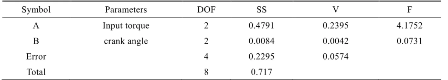
Analysis of Variance (ANOVA) of MRPI
An ANOVA is performed to identify the process parameter that is statistically significant affecting performance characteristics. Table 6 indicates that input torque is the most significant parameter affecting structure of four-bar partially compliant mechanism with largest value of F test of 4.1752.
Table 6. Results of ANOVA
Symbol Parameters DOF SS V F
A Input torque 2 0.4791 0.2395 4.1752
B crank angle 2 0.0084 0.0042 0.0731
Error 4 0.2295 0.0574
Total 8 0.717
4. Conclusions
The paper presents the combination of fuzzy logic controller with Taguchi method as a novel proposed optimization tool in for the four-bar partially compliant mechanism. The two objective functions such as angular displacement and stress of the small-length flexural pivot were formulated using theory of PRBM and principle of virtual work. Through the use of fuzzy logic-Taguchi method, this paper found the optimal process parameters such as input torque at level 1 of 3Nmand crank angle at level 1 of 100 degrees for maximizing angular displacement and minimizing the stress simultaneously. The result revealed that input torque is the most significant parameter affecting structure of for-bar partially compliant mechanism with largest value of F test of 4.1752. This proposed novel optimization method can be further utilized in engineering areas.
Acknowledgments
The authors acknowledge and thank the National Science Council of the Republic of China for their financial support of this study under Contract Number: NSC 99-2221-E-151 -004 -MY2.
References
[1] Tanık, E. and Söylemez, E., “Analysis and design of a compliant variable stroke mechanism”, Mechanism and Machine Theory, Vol. 45, pp. 1385-1394, 2010.
[2] Khatait, J.P., Mukherjee, S., and Seth, B., “Compliant design for flapping mechanism: A minimum torque approach”, Mechanism and Machine Theory, Vol. 41, pp. 3-16, 2006.
[3] Midhaa, A., Howell, L.L., and Norton, T.W., “Limit positions of compliant mechanisms using the pseudo-rigid-body model concept”, Mechanism and Machine Theory, Vol. 35, pp. 99-115, 2000.
[4] Dado, M.H., “Variable parametric pseudo-rigid-body model for large-deflection beams with end loads”, International Journal of Non-Linear Mechanics, Vol. 36, pp. 1123-1133, 2001.
[5] Hsiang, S.H., Lin, Y.W., and Lai, J.W., “Application of fuzzy-based Taguchi method to the optimization of extrusion of magnesium alloy bicycle carriers”, J Intell Manuf, Vol. 23, pp. 629-638, 2012.
[6] Venanzi, S., Giesen, P., and Castelli, V. P., “A novel technique for position analysis of planar compliant mechanisms”, Mechanism and Machine Theory, Vol. 40, pp. 1224-1239, 2005.
[7] Pei, X., Yu, J., Zong, G., and Bi, S., “An effective pseudo-rigid-body method for beam-based compliant mechanisms”, Precision Engineering, Vol. 34, pp. 634-639, 2010.
[8] Tsay, J., Chang, H.A., and Sung, C.K., “Design and experiments of fully compliant bistable micromechanisms”, Mechanism and Machine Theory, Vol. 40, pp. 17-31, 2005.
[9] Pucheta, M. A., and Cardona, A., “Design of bistable compliant mechanisms using precision–position and rigid-body replacement methods”, Mechanism and Machine Theory, Vol. 45, pp. 304-326, 2010.
[10] Gupta, A., Singh, H., and Aggarwal, A., “Taguchi-fuzzy multi output optimization (MOO) in high speed CNC turning of AISI P-20 tool steel”, Expert Systems with Applications, Vol. 38, pp. 6822-6828, 2011.