使用者群組網路設備管理平台
45
0
0
全文
(2) 使用者群組網路設備管理平台 A User Group Management Platform for Networked Appliances. 研 究 生:王聖全. Student:Sheng-Chuan Wang. 指導教授:張明峰. Advisor:Ming-Feng Chang. 國 立 交 通 大 學 網 路 工 程 研 究 所 碩 士 論 文. A Thesis Submitted to Institute of Network Engineering College of Computer Science National Chiao Tung University in partial Fulfillment of the Requirements for the Degree of Master in Computer Science June 2007 Hsinchu, Taiwan, Republic of China. 中華民國九十六年六月 ii.
(3) 使用者群組網路設備管理平台. 學生:王聖全. 指導教授:張明峰 博士. 國立交通大學網路工程研究所. 摘要 隨著資訊科技的發展,資訊設備具有的功能愈來愈多樣化,而具備連接網際網路的 設備,稱之為網路設備。目前,網路設備間互相通訊的架構主要分為兩種。一為區域網 路裡的網路設備通訊;另一種為透過居家閘道器存取使用者的網路設備。前者架構限制 使用者只能在區域網域內存取網路設備;後者限制網路設備之間的通訊必須透過居家閘 道器,造成系統的負載集中於居家閘道器。 我們提出了一個讓使用者網路設備能夠在網際網路上互相通訊的平台,並且透過群 組的概念去管理使用者的網路設備。我們使用雙網認證機制來認證使用者的網路設備, 和類似 Kerberos 架構處理請求服務的授權許可。系統中提供了「個人設備群組」及「使 用者群組」。個人設備群組包含使用者個人的網路設備,讓使用者可以安全且便利的存 取本身的設備。使用者群組則包含多個使用者的網路設備,讓使用者彼此之間可以做資 源的分享,例如檔案分享及影音串流服務。 我們使用群組金鑰做為群組成員存取控制的方法。成員間共同擁有一把群組金鑰。 利用群組金鑰可以達到訊息認證的功能,確保訊息為真正的群組成員所發出。此外,考 慮群組通訊的安全性,當有新成員加入或舊成員離開群組時,群組金鑰需要被更新。我 們以 Diffie-Hellman 金鑰交換演算法為基礎來達成群組金鑰協定,並以多播的方式來分 配金鑰以提高更換金鑰的效率。. iii.
(4) A User Group Management Platform for Networked Appliances. Student: Sheng-Chuan Wang. Advisor: Dr. Ming-Feng Chang. Institute of Networked Engineering National Chiao Tung University Abstract With the advancement of information technology, many novel functions have been provided, and Internet capable information appliances are referred to as networked appliances (NA). Currently, the architecture of communication among NAs can be classified into two categories. One is focusing on that NAs communicate with each other within an LAN, while the other is accessing NAs through a residential gateway (RGW). The former has a limitation that users can only access their appliances within an LAN; the latter is that any communication message among NAs has to be sent to the RGW, and the RGW forwards the message to the destination, which raises the overhead of the RGW. We propose a platform which enables user’s NAs to communicate with each other on the Internet, and manage NAs into groups. We use dual-connection device authentication to authenticate user’s NAs, and a Kerberos-like architecture for service request authorization. The platform accommodates Personal Device Groups (PDG) and User Groups (UG). A PDG includes a user’s own NAs such that a user can access his/her NAs conveniently and securely. A UG involves NAs of different users, providing resources sharing, such as file sharing and streaming service to others.. iv.
(5) For group access control, each member maintains an identical group key. The group key can be used for the message authentication and to ensure the message is indeed from a group member. In addition, we take the backward and forward secrecy into account; therefore, the group key has to be refreshed when a user joins or leaves a group. We are based on Diffie-Hellman key exchange algorithm for key agreement and distributing the group key using multicast for efficiency.. v.
(6) 誌謝. 首先我要感謝張明峰教授這兩年來的費心指導,方能順利完成此篇論文。於求學 過程中,在老師的啟發與教誨下,引導學生走向正確的方向,培養獨立思考的能力, 著實使我獲益良多。 還有要感謝網際網路通訊實驗室的同學們,博今、後瑋、名均及學弟們的支持與 鼓勵,給予我碩士生涯中奮鬥不懈的動力,由衷的感謝你們! 最後將此論文獻給我最親愛的家人。感謝您們在我求學期間全心全意的支持,讓 我得以專心的完成研究。. vi.
(7) Tables of Contents 摘要 ...........................................................................................................................................iii Abstract......................................................................................................................................iv 誌謝 ...........................................................................................................................................vi Tables of Contents ....................................................................................................................vii List of Figures............................................................................................................................ix List of Tables ..............................................................................................................................x Chapter 1 Introduction................................................................................................................1 1.1 Introduction ..................................................................................................................1 1.2 Related work.................................................................................................................1 1.3 Objective.......................................................................................................................3 1.4 Overview of the thesis ..................................................................................................3 Chapter 2 Background ................................................................................................................5 2.1 Secure Group Communication .....................................................................................5 2.2 Diffie-Hellman Key Agreement Protocol.....................................................................6 2.3 Dual-connection Device Authentication.......................................................................7 2.4 Kerberos Authentication ...............................................................................................8 2.5 Group Key Management ..............................................................................................9 2.5.1 Group Key Management Protocol...................................................................10 2.5.2 Tree-based Group Diffie-Hellman................................................................... 11 2.6 Summary.....................................................................................................................12 Chapter 3 Design of Our System..............................................................................................13 3.1 Overview ....................................................................................................................13 3.1.1 Architecture .....................................................................................................13 3.1.2 Components .....................................................................................................14 3.2 Authentication.............................................................................................................15 3.2.1 The Authentication Server ...............................................................................16 3.2.2 The Group Management Server ......................................................................19 3.2.3 UD-to-AD authentication ................................................................................20 3.3 Group Management ....................................................................................................21 3.4 Group Operation .........................................................................................................22 3.5 Group Key Management ............................................................................................23 3.6 Performance Analysis and Evaluation........................................................................27 3.7 Service Registration and Discovery ...........................................................................28 Chapter 4 System Implementation ...........................................................................................30 4.1 The Platform and Tools ..............................................................................................30 4.2 The Implementation of GMS......................................................................................30 4.2.1 Device Registration .........................................................................................30 4.2.2 Functions .........................................................................................................31 vii.
(8) 4.3 The Implementation of Group Operations..................................................................32 Chapter 5 Conclusions..............................................................................................................34 References ................................................................................................................................35. viii.
(9) List of Figures Figure 2-1 Figure 2-2 Figure 2-3 Figure 2-4 Figure 2-5 Figure 3-1 Figure 3-2 Figure 3-3 Figure 3-4 Figure 3-5 Figure 3-6 Figure 3-7 Figure 3-8 Figure 3-9 Figure 3-10 Figure 3-11 Figure 3-12 Figure 3-13. Diffie-Hellman Key Exchange Algorithm.........................................................6 Dual-connection device authentication..............................................................7 Kerberos authentication .....................................................................................9 A naive approach .............................................................................................10 Example of key tree in TGDH ......................................................................... 11 The architecture of our system ........................................................................14 Device authentication ......................................................................................16 Message flow of dual-connection device authentication.................................17 Message flow of ticket request for AD ............................................................18 Message flow of authentication for UD...........................................................18 Message flows of UD-to-AD authentication ...................................................21 The relationship of a PDG ...............................................................................22 Create a user group ..........................................................................................23 A key tree for key agreement...........................................................................24 Rekey: join.....................................................................................................25 Rekey: graceful departure ..............................................................................26 Departure during rekey process .....................................................................27 Service registration and discovery.................................................................28. Figure 3-14 Request services.............................................................................................29 Figure 4-1 The Flow chart of device registration ..............................................................31 Figure 4-2 The processing flow chart of the GMS............................................................32. ix.
(10) List of Tables Table 3-1 Messages exchanges between the NA and the GMS.........................................20 Table 3-2 Comparison table of refreshing the group key cost...........................................27 Table 4-1 The functions of group operations.....................................................................33. x.
(11) Chapter 1 Introduction 1.1 Introduction Information appliances, such as mobile devices, printers, cameras, etc, have become Internet capable and usually to be referred to as network appliances (NA). Some of them are having more functionalities and more powerful computing power, like taking pictures, video recoding, playing music, GPS receiver built-in, etc. As a result, there are many emerging applications dedicated to them, including GPS navigation system, Mobile TV, E-mail services and so on. Hence, users tend to have more and more networked appliances in the future. It is clear that how to enable them to communicate with each other conveniently and securely is becoming an important issue. At the same time, there are many standards, such as UPnP [1] and HAVI [2], focusing on the device communications in the home network. With the help of these technologies, we can integrate our home appliances, move digital audio/video content and share information among devices. Therefore, there is a trend with these smart information appliances working together. With the rapid expansion of the Internet, many new group-oriented applications, such as tele/video conferences and community games, have become so popular today that users have more opportunities to interact with each other. Thus, a reliable platform, where users can utilize their networked appliances to communicate and share resources with each other across the Internet is needed. To provide the access control and security over the Internet, a platform with secure group communication is necessary.. 1.2 Related work To enable simple and reliable connectivity among information appliances, many solutions have been proposed. One of the well-known, UPnP, offers network connectivity of 1.
(12) intelligent appliances and wireless devices. It is also an open, distributed architecture developed for proximity networking, and an Internet-based technology, built upon IP, TCP, UDP, HTTP, and XML, among others. In addition, UPnP enables communication between any two devices under the command of any control device on the network (LAN). Home Audio Video interoperability (HAVI), a standard for networking digital audio-video appliances, allows users home appliances to communicate with each other. It is focusing on the transfer and processing of digital audio-video contents among digital information appliances. IEEE 1394 standard is used as the interconnection medium, supporting isochronous communication which can guarantee packet delivery at fixed intervals, so that it can meet the real time constraints of audio and video streams. For accessing the networked appliances outside of the local network domain, some approaches using the Session Initiation Protocol (SIP) have been proposed [3, 4]. In those approaches, there were some problems, including device discovery and registration as well as security and access management that need to be resolved. These problems are essential for devices communications because of the following reasons. Device discovery involves how to locate a particular device, searching the device that users are interested in. Device registration allows NAs to register their name and information. Security protects the data integrity and confidentiality, while access management makes sure that only authenticated and authorized users have the access right. To provide security with network appliances, Tat Chan and Senthil Sengodan proposed a solution based on SIP [5]. They focus on the system architecture where NAs can communicate directly through the Residential Gateway (RGW). The RGW is responsible for authentication, authorization, and encryption of SIP messages. They use secret key encryption to achieve device communication security. For access control, which is related to authorization, they proposed a rule-based access right system with centralized authorization performed at the RGW. 2.
(13) However, both UPnP and HAVI are mainly designed for the home domain network. This limitation means that the user can only access network appliance on the local network domain. Another approach accesses the network appliances through the RGW, which implies the loading of the RGW will be heavy. Hence, we conceive an idea that users can connect their network appliances together through a platform on the Internet. Users can directly access their network appliances on the Internet as compared to be restricted on the home network. Unlike accessing network appliances through a RGW, in our system, users can access network appliances in the same group of users directly, which reduces the overhead of the server.. 1.3 Objective We propose a secure and reliable platform that can be used on the IP network, where users can access their networked appliances and share the resources of the appliances with others. For the user authentication, we use an E.164 number based user authentication approach for VoIP [6]. Moreover, we exploit an authentication server based on Kerberos architecture to support single sign-on services [7], which can enable a user authenticate once for accessing other services in the system afterwards. Furthermore, our platform supports group operations, such as creating, joining and leaving specific groups. This allows users to manage their NAs in convenient way and even to establish their own groups for providing services. To support access control, security, data integrity and confidentiality across the Internet, group key management is employed in the platform.. 1.4 Overview of the thesis The remaining of this thesis is organized as follows. Chapter 2 describes the essential background knowledge related to our system. Chapter 3 provides the details of our system 3.
(14) design. Chapter 4 presents the implementation issues. Finally, the conclusion is given in Chapter 5.. 4.
(15) Chapter 2 Background In this thesis, we present a user group management platform for networked appliances. These appliances communicate with each other across the Internet; therefore, security is an important requirement. We will present the basic secure group communication concepts at first. After that, those schemes used in our system will be elaborated.. 2.1 Secure Group Communication IP multicast can be used in group communication for efficient data transferring; therefore, many applications have adopted this mechanism to transmit data for efficiency. However, IP multicast does not provide a mechanism where only authorized users can access the data. Thus, access control and authentication is not provided. To guarantee only group members have the access authority, access control and authentication is required. In a group, all members possess an identical secret key that is referred to as group key is a major approach used to support group access control. The group key can be used for data encryption to provide confidentiality and integrity among group members. Encryption can transfer the original plain text into the ciphered text, which is unreadable to others and only can be recovered using the encryption key. Hence, only members of the group can decrypt the ciphered text, obtaining the useful information. The group key should be refreshed frequently to guarantee group secrecy. When a new member joins the group, we should change the group key to prevent the new member from accessing the previous group information. Likewise, when a group member leaves the group, the group key should be changed as well to avert the leaving member from accessing the subsequent group communication. The former property is called forward secrecy, and the latter is backward secrecy. Both these two properties should be satisfied in a group. 5.
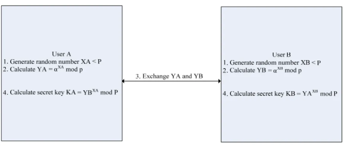
(16) communication system.. 2.2 Diffie-Hellman Key Agreement Protocol Diffie-Hellman key exchange algorithm [8] can be used to establish a shared secret key between two users, which enables encryption of subsequent message communication session. Therefore, we can apply the algorithm to set up a common group key, providing group communication security. The Diffie-Hellman key exchange algorithm is illustrated in Figure 2-1. There are two public known values, p and α, where p is a prime and α is a primitive root of p. Assume users A and B would like to exchange a key. First, both users A and B generate random numbers, XA < p and XB < p, respectively. Second, they individually calculate public values YA and YB, such that YA = αXA mod p and YB =αXB mod p. Afterwards, they exchange YA and YB with each other. After receiving the public values YA and YB separately, they can compute their common secret keys KA and KB. To take advantage of Diffie-Hellman, computing discrete logarithms is very difficult to achieve. Thus, it is hard to attain the user’s secret key to compute the common shared secret key.. Figure 2-1 Diffie-Hellman Key Exchange Algorithm. 6.
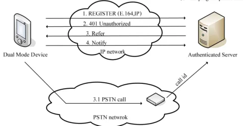
(17) 2.3 Dual-connection Device Authentication Dual-connection device authentication can be employed in our system to authenticate the identities of the user’s network appliances. E.164 number, the telephone numbers used worldwide, can avoid the situation that two users use the same numbers. Therefore, Dual-connection device authentication adopting E.164 will be a practical approach in our system to authenticate the identities of users. We introduce the dual-connection device authentication mechanism used in our system, which is shown in Figure 2-2. The network appliance sends SIP REGISTER message carrying the telephone number specified by users to our authentication server (AS). After receiving the message, AS will response the SIP 401 Unauthorized message and send SIP message REFER including the telephone number of the caller id receiver connected to the AS. The network appliance then uses the number to make a phone call to the AS. The phone call will be ended automatically by the AT commands implemented in the AS. Afterwards, the networked appliance will notify the AS that the GSM call has been finished. The AS compares the phone number received from the caller id receiver to the number specified by the user. The authentication will be successful if the number is the same. Otherwise, it will be failed.. Figure 2-2 Dual-connection device authentication. 7.
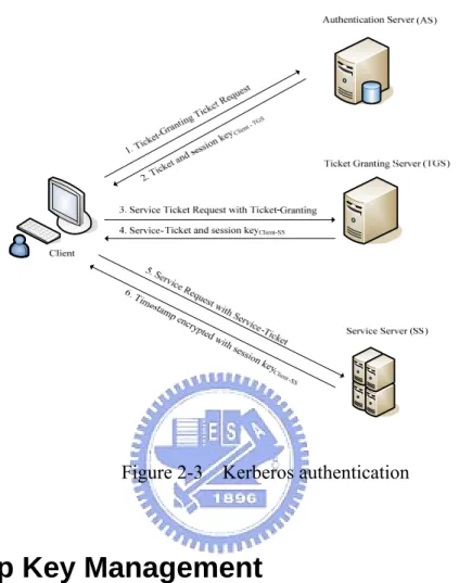
(18) 2.4 Kerberos Authentication Kerberos is a common used authentication protocol, enabling only authorized users can access the services provided by servers on the distributed network environment. Kerberos adopts symmetric encryption mechanism to provide secure authentication service compared to public key encryption. In addition, it can support single sign-on (SSO) services, i.e., users authenticated once can access multiple services in the system for reducing the authentication cost and time. Therefore, we employ Kerberos authentication to save the times of required authentication in our system. We briefly introduce the idea of Kerberos authentication protocol as follows and the illustration is given in Figure 2-3. Authentication Server (AS) stores the password of all users in the database and is responsible for generating the granting ticket. Ticket-Granting Sever (TGS) issues the service ticket for the particular service to clients. At beginning, the client sends ticket-granting request to the AS. The AS checks whether the username exists or not, sending the granting ticket as well as the secret key between the client and TGS encrypted with the session key (derived from the password) of the client if it exists. When requesting services, the client sends the granting ticket, requested service ID, and the client’s authenticator, composed of the client ID and timestamp to the TGS. Upon receiving the message, the TGS decrypts the ticket, obtaining the secret key shared by the client and TGS. The TGS will use the key to decrypt the authenticator, checking if the client ID matches the one in the granting ticket. Afterwards, the TGS sends the service ticket and the secret key between the client and service server back. Upon receiving the service ticket from TGS, the client can access the service server now. The client sends the message including the service ticket and authenticator to the service server. The service server will increase the timestamp from the authenticator by 1 and reply the message encrypted with the shared key between the client and the service server. After. 8.
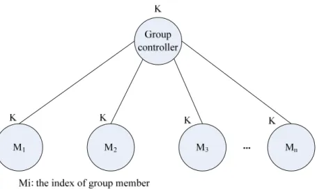
(19) checking the timestamp is added correctly, the client will trust the service server, sending the service request to it.. Figure 2-3 Kerberos authentication. 2.5 Group Key Management Group key can provide data integrity, authentication and confidentiality in the group communication system. Hence, how to distribute the group key efficiently and securely to the group members is an important issue. We consider the naïve approach based on a group controller to distribute the group key to each member, which is given in Figure 2-4. Each member shares its secret key with the group controller. The group controller distributes the group key encrypted with the secret key of each member. The approach is simple and easy to implement, but it is not efficient and scalable owing to the high encryption cost. The group controller has to encrypt the group key as many times as the number of group members. When group members join or leave the group, it will be inefficient to refresh the group key.. 9.
(20) Figure 2-4 A naive approach. 2.5.1 Group Key Management Protocol The Group Key Management Protocol (GKMP) [9] can distribute the group key to group members without the need of centralized key distribution center. It supports multicast as well if the multicast service is available. GKMP defines the group controller (GC) with authority to perform group actions, such as create key, distribute key, and the group member who is not the group controller to assist creating group key and validating the GC. In the group key creation, the first group member assists the group controller to establish the group key. During the group key creation, the GTEK (Group Traffic Encryption Key) and GKEK (Group Key Encryption Key) is generated. The GTEK is used for messages encryption in the subsequent communication. To distribute the group key, the session key encryption key (SKEK) is created to encrypt GTEK and GKEK for transmission. The GC then sends key packet (KP) consisting of GTEK and GKEK to other group members. When joining or leaving the group, rekey is necessary to change the GTEK and GKEK of group members. The GC sends the rekey message consisting of KP encrypted with the GKEK to other members. However, the group forward secrecy is not satisfied when an original group member knowing the GKEK leaves the group. 10.
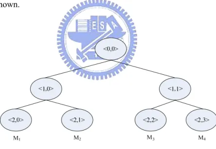
(21) 2.5.2 Tree-based Group Diffie-Hellman Tree-based Group Diffie-Hellman (TGDH) [10] makes use of Diffie-Hellman key exchange and key trees to distribute the group key more efficiently. An example of Key trees in TGDH is given in Figure 2-5. Each node <i, j> maintains its corresponding secret key, K<i, k j> and blinded key (public key), BK<i, j> which equals to f (K<i, j>), where f (k) = α mod p. In addition, each node knows the set of keys from its parent to the root node. For instance, member M1 knows the keys, {K<2,0>, K<1,0>, K<0,0>}. K<i,j> is computed based on the formula: K <i,j> = (BK<i+1, 2j>)K<i+1, 2j+1> mod p = (BK<i+1, 2j+1>)K<i+1, 2j> mod p All group members can compute the group key recursively from the formula, since the blind keys is public known.. Figure 2-5 Example of key tree in TGDH. When a member wants to join the group, he broadcasts a join request including its blinded key to all existing members. The new member will join the position, where the shallowest place in the key tree. Each member will insert the new member into their key tree after receiving the request. The sponsor node, which is responsible for generating new group. 11.
(22) key when joining or leaving event occurs, will send all the new generated blinded keys to others members. Upon receiving the blinded keys, the other members can compute the new group key. Likewise, when an existing member leaves the group, the sponsor will calculate the new group key, sending the blinded keys to all members except for the leaving member. We can observe that the forward and backward secrecy are achieved when joining or leaving event occurs. The approach is in the category of contributory group key management, where every member equally contributes a part of the group key, avoiding the single point of failure problem. However, in the approach, each member has to maintain the whole key tree.. 2.6 Summary We use Kerberos-like authentication to authenticate the requests from the NAs. The authentication method developed by our laboratory for dual-mode handsets is used to authenticate a user’s NAs first. After the authentication, the NA acquires a grant ticket for service request authorization. To construct a use group management platform on the Internet, we use Diffie-Hellman key exchange algorithm to distribute the new group key when a user joins or leaves the group, assuring the backward and forward secrecy is satisfied. The design of our system will be elaborated in next chapter.. 12.
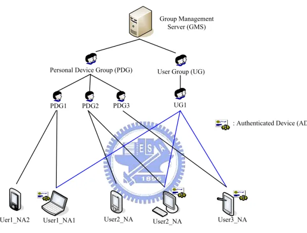
(23) Chapter 3 Design of Our System 3.1 Overview We design a user group management platform for network appliances connected on the Internet. The users can create their own user group to share resources with others using their network appliances. In addition to the user groups, our system automatically classifies user’s devices into their own personal device group, which enables they can access their own network appliances conveniently. The group information is maintained in the group management server. To authenticate network appliances, we employ the dual-connection device authentication in the authentication server. For group access management, each member shares a common group key, so that they can use it to do message authentication, assuring the message is indeed from the group members. In addition, we take forward secrecy and backward secrecy into account, so the group key has to be refreshed when group members join or leave a group.. 3.1.1 Architecture The system architecture is given in Figure 3-1. An authenticated device (AD) is a network appliance which has been authenticated by the authentication server. Otherwise, it is called unauthenticated device (UD). We define two types of groups in the system, personal device groups (PDG) and user groups (UG). A PDG, as the name suggests, includes a user’s own personal networked appliances, which can be ADs and UDs. On the other hand, a UG, which is created by a user, can involve different user’s networked appliances that have been authenticated (AD). A UG can support resources sharing to its group members, such as streaming services and file sharing. Our system consists of two types of servers, the authentication server and the group. 13.
(24) management server. The authentication server is responsible for user’s device authentication using dual-connection authentication mechanism. The group management server supports group operations, such as creation, joining, and leaving, maintaining the group information, verifying the device’s authorization.. Group Management Server (GMS). Personal Device Group (PDG). PDG1. PDG2. User Group (UG). UG1. PDG3. : Authenticated Device (AD). Uer1_NA2. User1_NA1. User2_NA. User2_NA. User3_NA. Figure 3-1 The architecture of our system. 3.1.2 Components We elaborate the components of our user group management platform as follows. z. Network appliances: We divide NAs into two categories, ADs and UDs. A NA which has passed dual-connection device authentication is referred to as an AD, while the others that have not performed or can not perform dual-connection device authentication are UDs because of limited computing power. An AD is able to control the UDs, but the UDs can only comply with the AD.. 14.
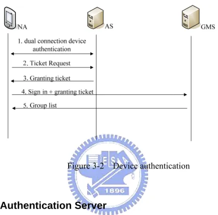
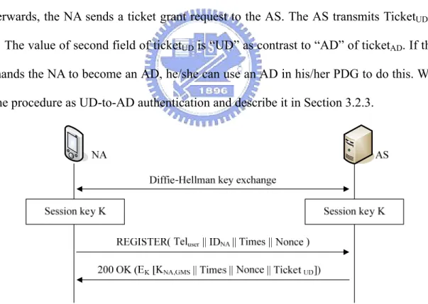
(25) z. Authentication server (AS): Each network appliance has to be authenticated by the AS before signing in the system. In the authentication procedure, a NA needs to make a phone call to the AS, so that the AS can trust the NA and recognize it as an AD. On the other hand, those NAs that cannot make phone calls are recognized as UDs by the AS.. z. Group management server (GMS): The group management server maintains group information of the personal device groups and user groups. The group information is stored in a database maintained in the GMS. When handling group operations, such as creating and joining groups, the GMS will verify the authorization of the NAs, allowing only ADs to do this. Furthermore, the GMS maintains the IP addresses and the identifiers of NAs after they sign in the system.. 3.2 Authentication We use the phone number and device name specified by users to represent the identifier of a network appliance in the system. The phone number claimed by users is authenticated by dual-connection device authentication mechanism. In addition, we use a Kerberos-like architecture to authenticate requests for service in the system. We illustrate the authentication mechanism in Figure 3-2. At the beginning, the NA performs dual-connection device authentication, in which a session key is generated between the NA and the AS using the Diffie-Hellman key exchange algorithm. The detail of dual device authentication will be described in Section 3.2.1. The NA, however, may not have the ability to make a phone call. In this case, the AS provides another authentication called “UD authentication”, which will also be elaborated in Section 3.2.1. To distinguish an AD from a UD, we design two kinds of tickets for them, which are denoted as “TicketAD” and “TicketUD”, respectively. The ticket is encrypted with KGMS, which is shared between the AS and the GMS in advance and used for ticket encryption. The AS transmits the corresponding ticket to the 15.
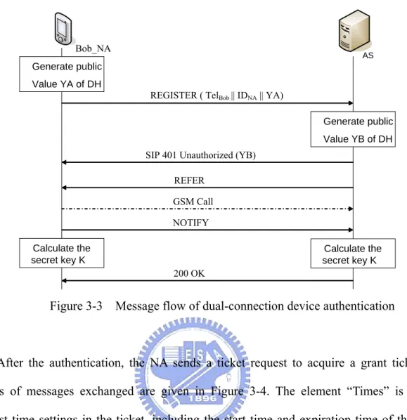
(26) NA according to the authentication it has performed. With the granted ticket, the NA can sign in the GMS. If the granted ticket is ticketAD, the NA can get the group list, creating and joining other groups; otherwise, the NA only can comply the instructions of ADs.. Figure 3-2 Device authentication. 3.2.1 The Authentication Server We base on the authentication server developed by Chiang [11], Internet Communication Lab, NCTU, to provide the device authentication in our system and develop our own functions. We illustrate the dual-connection device authentication message flow in Figure 3-3. During the authentication procedure, a share key K is calculated between the NA and the GMS using the Diffie-Hellman key exchange algorithm. We assume Bob registers his NA with the AS. Bob specifies his phone number and the name of the NA and generates a public key YA in the Register message. The AS first responses a SIP 401 Unauthorized message with a public key YB and then authenticates the phone number by sending a “REFER” message to request a GSM call from the NA. After verifying the phone number successfully, a secret key K can be calculated in both the NA and AS.. 16.
(27) Bob_NA. AS. Generate public Value YA of DH REGISTER ( TelBob || IDNA || YA). Generate public Value YB of DH SIP 401 Unauthorized (YB) REFER GSM Call NOTIFY. Calculate the secret key K. Calculate the secret key K 200 OK. Figure 3-3 Message flow of dual-connection device authentication. After the authentication, the NA sends a ticket request to acquire a grant ticket. The details of messages exchanged are given in Figure 3-4. The element “Times” is used to request time settings in the ticket, including the start time and expiration time of the ticket. The nonce is a random value and will be returned from the AS to guarantee the response is not replayed by an opponent. The NA sends the ticket request message with Bob’s phone number, the identifier of NA, times, and a nonce to the AS. Upon receiving the ticket request, the AS sends ticketAD and a secret key encrypted with the shared key K that is calculated in the dual-connection device authentication. TicketAD is encrypted with KGMS shared between the AS and the GMS. The secret key KNA, GMS in Ticket AD is used for the NA and the GMS, and the value AD indicates the ticket belonging to ticketAD.. 17.
(28) Figure 3-4 Message flow of ticket request for AD. In addition, we describe the mechanism of UD authentication and illustrate it in Figure 3-5. At first, the NA and the AS use Diffie-Hellman algorithm to establish a secret key. Afterwards, the NA sends a ticket grant request to the AS. The AS transmits TicketUD to the NA. The value of second field of ticketUD is “UD” as contrast to “AD” of ticketAD. If the user demands the NA to become an AD, he/she can use an AD in his/her PDG to do this. We refer to the procedure as UD-to-AD authentication and describe it in Section 3.2.3.. Figure 3-5 Message flow of authentication for UD. 18.
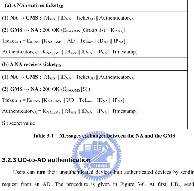
(29) 3.2.2 The Group Management Server The GMS verifies grant tickets to authenticate requests from NAs. According to the type of the grant tickets (AD or UD), different response are returned from the GMS. We summarize the message exchanges of these two types in Table 3-1 and explain the details as follows:. a. A NA receives ticketAD The authenticator consists of the user’s phone number, the identifier and IP address of the NA, as well as a timestamp. The timestamp indicates the authenticator is valid for a short period of time to prevent an opponent from stealing it for replaying attack. The GMS decrypts the ticket with the key KGMS that is shared between the AS and the GMS in advance and receives the key KNA,GMS for decrypting the authenticator. The GMS then compares the user’s phone number, the identifier of NA, IP address with those in the authenticator. If all are the same, the GMS believes that the ticket is from its owner and transmits the group lists as well as KPDG encrypted with KNA,GMS to the NA. KPDG is a key shared among all NAs that are ADs in PDG. We use the key to provide message authentication and confidentiality among ADs in group communication. The group lists include the PDGs and the UGs, so that the NA can access other devices in its PDG and request services from UGs.. b. A NA receives ticketUD Basically, the message exchanges are similar to that of receiving ticketAD except for the following. In the response message from the GMS to the NA, a secret value encrypted with KNA,GMS is transmitted. With the secret value, a UD can authenticate an AD using message authentication; therefore, when an AD want to access a UD in a PDG, the AD has to request the secret value from the GMS at the first time.. 19.
(30) (a) A NA receives ticketAD (1) NA → GMS : Teluser || IDNA || TicketAD || AuthenticatorNA (2) GMS → NA : 200 OK (ENA,GMS [Group list + KPDG]) TicketAD = EKGMS [KNA ,GMS || AD || Teluser || IDNA || IPNA] AuthenticatorNA = KNA,GMS [Teluser || IDNA || IPNA || Timestamp] (b) A NA receives ticketUD (1) NA → GMS : Teluser || IDNA || TicketUD || AuthenticatorNA (2) GMS → NA : 200 OK (ENA,GMS [S] ) TicketUD = EKGMS [KNA,GMS || UD || Teluser || IDNA || IPNA] AuthenticatorNA = KNA,GMS [Teluser || IDNA || IPNA || Timestamp] S : secret value Table 3-1 Messages exchanges between the NA and the GMS. 3.2.3 UD-to-AD authentication Users can turn their unauthenticated devices into authenticated devices by sending the request from an AD. The procedure is given in Figure 3-6. At first, UDA sends the authentication request with ticketUD and authenticatorA to the GMS. The GMS verifies the ticket and the authenticator to assure this request is indeed from UDA and forwards the request to ADB, which is in the user’s PDG. After receiving the confirmed message from ADB, the GMS will recognize UDA as an AD. Afterward, the GMS will transmit KPDG, which is shared by all ADs in the PDG and encrypted with KA,GMS to UDA.. 20.
(31) Figure 3-6 Message flows of UD-to-AD authentication. 3.3 Group Management We use the GMS to maintain the necessary group information, including PDGs and UGs. We describe how these two types of groups are managed as follows:. a. Personal Device Group When a NA signs in the GMS, the GMS will determine the NA belongs to which PDG according to the phone number of the user and the device name, recognizing the NA as AD or UD according to the grant ticket. Depending on the NA is AD or UD in a PDG, the response from the GMS is different. Before that, we describe the relationship of ADs and UDs in a PDG and illustrate the relationship in Figure 3-7. In a PDG, all ADs share an identical group key “KeyPDG”, while each UD maintains its secret value with the GMS. To access the resource of a UD, an AD has to know the UD’s secret value in advance; thus, the UD can authenticate requests from the AD. To know the secret value of a UD, the AD requests the value from the GMS. On the other hand, for authentication between ADs, we use the group key to authenticate each other in the PDG. Therefore, the GMS returns KeyPDG to an AD and a specific secret value to a UD.. 21.
(32) Figure 3-7 The relationship of a PDG. b. User Group The GMS allows users to create their specific UG using a NA that has been authenticated (AD). We define two types of UGs, public and private. A public group is open to all members in a UG; therefore, each user can join the group without any permission. However, a private group is limited to specific users. We define the AD that creates the private group as the group owner. To join a private UG, other ADs need to have the owner’s approval. In a private UG, the group owner has to authenticate the request is indeed from the group members. For the purpose, each member in the same group shares an identical group key. We use digest authentication for SIP using the group key for message authentication [12]; therefore, when requesting services in a UG, each member can use the group key for message authentication.. 3.4 Group Operation Our system supports three user group operations, creating, joining, and leaving group. We describe each operation as follows:. 22.
(33) To create a UG, an AD sends a REGISTER message to the GMS, specifying the group name, group type (public or private), and group description. The messages exchanged are depicted in Figure 3-8.. AD. GMS. REGISTER (Name, type, description) 200 OK. Figure 3-8 Create a user group. To join a public UG, an AD sends an INVITE request to the GMS. Upon receiving the request, the GMS adds the new member to the UG and responses an OK message to the AD. While joining a private UG, we have to consider the backward secrecy; thus, the group key must be refreshed. The details are given in Section3.5. Similar to joining a UG, when a member leaves a public UG, the member transmits a BYE message to the GMS. Upon receiving the message, the GMS deletes the member from the UG. When leaving a private UG, the member sends a BYE request to the group owner. The group owner deletes the leaving member and the group key is refreshed to satisfy the forward secrecy. The details are described in Section 3.5 as well.. 3.5 Group Key Management We use the Diffie-Hellman key exchange algorithm to achieve a common group key and construct a tree structure to update the group key efficiently. A tree is maintained by a group owner and each of other members maintains two children node. Figure 3-9 shows an example of a key tree we used for group key agreement. Each node ui shares secret keys with its children nodes. For example, u1 shares K12 and K13 with its two children nodes, u2 and u3. The 23.
(34) Kij is established when a member joins a group and used when a member leaves a group for key refreshing. In addition, each node shares a common group key.. Figure 3-9 A key tree for key agreement. Figure 3-10 shows an example when a new member u6 joins the group. Gk is the original group key shared by all group members. At first, u6 sends a join request with its public key (αK6) to the group owner, u1. If u1 accepts the request, u1 returns an OK message with the original public group key (αGk) and adds u6 to the key tree at the shallowest rightmost position. In the example, u6 becomes the left child node of u3. U3 and u6 exchanges the public keys, ' 3. ' 6. α K and α K to establish the secret key K36 that equals to α K. ' ' 3K6. mod p . After that, u1. multicasts αK6 to the group members except for the new member u6. Upon receiving αK6, the group. members. from. u1. to. u5. can. compute. the. new. group. key. Gk' = (α k 6 )Gk mod p = α k 6 Gk mod p by applying Diffie-Hellman key exchange alogorithm. Likewise, u6 can compute the group key Gk' = (α Gk )G6 mod p = α k 6 Gk mod p .. 24.
(35) αk. 6. G α ). ( 2 . OK. k. K12. K 24. K12. K13. K 25. K 24. K 25. K13. K12. K 24. K 25. K13. αk. 6'. αk ' 3. Gk '. K12. K 24. K 25. K 36 = α. αk. K13. αk. 6. αk. 6. αk. 6. 6. K 36. K 3' K '6. Gk ' = (α K6 )G k = α. K 6Gk. mod p. Figure 3-10 Rekey: join. We discuss two cases about leave. One is when a group member leaves, the leaving member notifies the group owner, which is called graceful departure. The other is ungraceful departure, which is a group member leaves without informing the group owner. We describe the two cases as follows. Figure 3-11 shows an example, where a group member u2 leaves the group and notifies the group owner. In this case, the group owner u1 deletes u2 from the key tree. The group owner then chooses the deepest and rightmost member in the key tree to replace the leaving member. In this case, u6 is selected; the group owner u1 notifies u6 to add the children nodes of u2 and informs u3 that the child node u6 has left. U1 then establishes the secret key K16 with u6, and u6 establishes the secret key K46 and K56 with its two children u4 and u5 using Diffie-Hellman key exchange algorithm. The group owner generates a new secret key Gk’ and multicasts Gk’ encrypted with the secret key shared with the children nodes. In the example, u1 multicasts Gk’ encrypted with K16 and K13 to u6 and u3, respectively. U6 then decrypts Gk’ 25.
(36) by K16 and multicasts Gk’ encrypted with K46 and K56 to u4 and u5, separately.. K12. K 24. K 25. K13. K 36. K16. K 46. K13. {G k '}K 16. {Gk '}K13. K 56. Gk '. Figure 3-11 Rekey: graceful departure. To detect ungraceful departure, each group member sends “keep alive” message periodically to its children node. If a member detects its child has left, the member will notify the group owner. Then the group owner deletes the leaving node from the key tree, adjusting the key tree and refreshing the group key as the graceful leave case we have mentioned above. In addition, we describe a case when refreshing the group key, there are members happening to leave a group. In normal case, if a member node multicasts a new key to its children, the children will response ACK message indicating the new key has been received; thus, a parent node can detect if its child has left a group by this. Figure 3-12 shows an example, in which a parent node detects that its child has left the group during rekey process. In the example, u2 multicasts the new group key to its children node, u4 and u5. U4, however, has left the group without informing the group owner. Therefore, u2 will not receive the ACK message from u4 and consider that u4 has left the group. U2 then reports the group owner u1 that the departure of u4. The group owner adjusts the multicast key tree, choosing u9 that is the deepest and rightmost node of the sub-tree of the leaving node to replace u4. At the same time, u1 notifies u9 the children node of u4. Afterward, u2 and u9 perform Diffie-Hellman key exchange to establish the secret key K29. Likewise, u8 and u9. 26.
(37) establish K89. U2 retransmits Gk’ encrypted with K29 to u9, continuing the rekey process.. u1. u1. u2 G k ' {K 24 }. u4 u8. u3. u2. G k ' {K 25 }. u5. u1 u3. K 29. u6. u7. K 89. u9. G k ' {K 29 }. u9. u5. u6. u7. u9. u8. u4 has left the group. u2. u3 u5. u6. u7. u8 u2 retransmits the group key. establish the secret key. G k' : the new group key. Figure 3-12 Departure during rekey process. 3.6 Performance Analysis and Evaluation We analyze the cost of joining and leaving process when refreshing the group key, and key storage of each member. Table 3-2 shows the comparison result of our approach and TGDH. The notation M stands for modular exponentiation, E stands for encryption/decryption, and h is the height of the key tree. In average, each member needs one modular exponentiation cost in the joining process of our algorithm, and no extra cost of sponsor is required. Though in the leaving process, our algorithm has the overhead of encryption. However, in TDGH, each member has to maintain the whole key tree and h secret keys. In contrast, each member only maintains two children nodes except for the group owner and 3 secret keys in our approach; thus reducing the required key storage.. Scheme/. Joining process. Feature. Member. TGDH Ours approach. Leaving process. Key Storage. Sponsor. Member. Sponsor. Member. 1M. 2(h-1)M. 1M. 2(h-1)M. h. 1M. -. 1M + 2E. -. 3. Table 3-2 Comparison table of refreshing the group key cost. 27.
(38) 3.7 Service Registration and Discovery After users create their user groups or join other user’s group, they can register services with the GMS. We describe how users register and discovery services. Figure 3-13 shows the message flow of service registration and discovery. In this example, NA1 registers a service with the GMS and NA2 wants to receive this service. NA2 has to join the user group to acquire the service list. After acquiring the service list, NA2 can receive this service from NA1. 1. Register Services 2. OK NA1. GMS. e ec. R 5. c vi er. 3. Jo 4. in Se G ro rv up ic eL ist. eS iv e. NA2. Figure 3-13 Service registration and discovery. We use XML format to describe services when registering services. We give the details of service description as follows: <serviceDescription> <name> ServiceName </name> <type> ServiceType </type> </serviceDescription> Suppose that Peter creates a user group and wants to share a streaming service called “Meichu Contest” to his friends. He uses his networked appliance, NA1, sends a REGISTER message specifying the service name as “Meichu Contest” and service type as streaming 28.
(39) service. Figure 3-14 shows an example, where his friend, Alice, wants to watch the “Meichu contest” provided by Peter. Alice uses her networked appliance, NA2, to join the user group of Peter. After Alice acquires the service list of Peter’s user group and decides to get this service, Alice uses NA2 to send an INVITE message to the GMS. The GMS returns a “302 Move Temporarily” message to the NA2. NA2 then sends an INVITE message to NA1 and start to receive the streaming service.. Figure 3-14 Request services. 29.
(40) Chapter 4 System Implementation We have implemented the AS and GMS on PCs. In addition, we have developed programs for NA on PDAs, laptops, and PCs. We will describe the development tools and software used in our system first, and then the implementation of system components.. 4.1 The Platform and Tools We construct our system using Mini UA and SIP UA, developed by Computer &Communication Research Laboratories (CCL) of Industrial Technology Research Institute (ITRI). Mini UA is the mobile device version of SIP UA; therefore, we use Mini UA for PDA development and SIP UA for general PC implementation. The development tool for Mini UA and SIP UA are Microsoft Embedded Visual C++ and Microsoft Visual C++ 6.0.. 4.2 The Implementation of GMS 4.2.1 Device Registration Users have to register their NAs to the GMS before requesting services from the GMS. We first describe the registration procedure of the GMS. Figure 4-1 shows the flow chart of the procedure. After verifying the grant ticket, the GMS determines the type of registered NA belonging to AD or UD. According to the username in the register message, then the GMS searches the database to decide if the PDG has already existed. If the PDG is not existed, the GMS will create a PDGkey for this group. Afterward, the record of the registered NA is inserted into the database.. 30.
(41) Receive register requests. Init. Valid Ticket. NO. YES Create a new PDG. NO. Is the PDG of the user existing. YES Add the new member to the PDG. Generate a keyPDG. Generate a secret value. UD. Determine the type of the NA. AD or UD AD. Send 200 OK with the secret value. Send 200 OK with the keyPDG. Send 401 response. Figure 4-1 The Flow chart of device registration. 4.2.2 Functions Figure 4-2 illustrates the processing flow chart of the GMS. When receiving requests from the NAs, the GMS will verify the ticket and check if the client has registered. The GMS maintains the list of user group and services, supporting users to create groups. After verifying the ticket, registration procedure is executed if the message type is “REGISTER”; otherwise, according to the request message type, creating group, returning group or service lists will be performed, respectively.. 31.
(42) Figure 4-2 The processing flow chart of the GMS. 4.3 The Implementation of Group Operations We have implemented the program run on NAs based on SIP UA. We modify the SIP UA to support the group operations, joining, leaving, and creating groups. Table 4-1 shows the functions we have developed for supporting group operations. The function Create_Group is used when a user wants to create a user group. The parameter is the user group name, group type (public or private), group description, and the identifier of the NA that creates the group. The function Join_Group is used when a NA sends request for joining a user group. The parameter group public key is generated by a NA and is used for computing a new group key. The function Leave_Group is used when a NA leaves a group, and the parameter is the group name, and the identifier of NA.. 32.
(43) Function name. Corresponding SIP Method. Function parameters. Create_Group. REGISTER. GroupName, type, description, identifier. Join_Group. INVITE. GroupName, group public key, identifier. Leave_Group. BYE. GroupName, identifier Table 4-1 The functions of group operations. 33.
(44) Chapter 5 Conclusions We have designed a platform that organizes network appliances of users into personal device groups, where users can access their network appliances on the Internet. In addition, users can create user groups to share resources with others. The Internet, however, is an open network, where anyone could be impersonated; therefore, authenticating the identity of a user is required. We adopt a Kerberos-like architecture for device authentication in our system. To acquire a grant ticket, a user has to perform the dual-connection device authentication using their network appliances. With the grant ticket, the user can sign in the group management server to obtain the list of groups, to access their devices in their PDG, to create user groups for sharing, and to join other groups to get services. In group management and communication, we have to ensure that only group members can access the resources. Our solution is that each member shares a group key in a group, in which the primary challenges are how to agree a common group key and refresh the group key when a user joins or leaves the group. We adopt Diffie-Hellman key exchange algorithm and extend it for our group key agreement. To refresh the group key, we use multicast to transmit the public key that is needed to calculate the new group key for efficiency; thus, each group is associated with a group distribution key tree used for multicasting the group public key. Upon each member receiving the public key, the new group key can be calculated individually. In future work, device control can be considered in the platform. A general model to discover the functionalities is provided in network appliances is a major concern, and to support those appliances designed for some specific protocols, such as X10 and LonWorks can be contemplated.. 34.
(45) References [1] UPnP, http://www.upnp.org [2] HAVI, http://www.havi.org [3] S. Moyer, D. Marples, and S. Tsang, “A Protocol for Wide Area Secure Networked Appliance Communication,” IEEE Commun. Mag., Oct. 2001. [4] M. Rahman, D. Braun, D. Bushmitch, “ A Framework to Access Networked Appliances in Wide Area Networks”, Consumer Communications and Networking Conference, Jan. 2005. [5] T. Chan, S. Sengodan, “On Applying SIP Security to Networked Appliances”, IEEE 4th International Workshop on, pages 31-40, 2002. [6] Daniel Collins, “Carrier Grade Voice over IP”, McGraw Hill, New York, 2001. [7] C. Neuman, T. Yu, S. Hartman, “The Kerberos Network Authentication Service (V5)”, RFC 4120, IETF, July 2005. [8] William Stallings, “Network Security Essentials: Applications and Standards”, N.J: Prentice Hall, 2000. [9] H. Harney, C.Muckenhirn, “Group Key Management Protocol (GKMP) Specification”, RFC 2093, IETF, July 1997. [10] Y. Kim, A. Perrig, G. Tsudik, “Tree-Based Group Key Agreement”, ACM Transactions on Information and System Security (TISSEC), 2004. [11] Chun-Hsien Chiang, “A Mobile Payment System for PLMN/IP Dual Networks”, National Chiao Tung University, June 2006. [12] J. Rosenberg, H. Schulzrinne, G. Camarillo et al, “SIP: Session Initiation Protocol”, RFC3261, IETF, June 2002.. 35.
(46)
數據
+7
相關文件
For periodic sequence (with period n) that has exactly one of each 1 ∼ n in any group, we can find the least upper bound of the number of converged-routes... Elementary number
Write the following problem on the board: “What is the area of the largest rectangle that can be inscribed in a circle of radius 4?” Have one half of the class try to solve this
3.16 Career-oriented studies provide courses alongside other school subjects and learning experiences in the senior secondary curriculum. They have been included in the
We explicitly saw the dimensional reason for the occurrence of the magnetic catalysis on the basis of the scaling argument. However, the precise form of gap depends
Children explore the online world alone, but they use message boards to share what they find and what they do in the different creative studios around the virtual space.. In
The evidence presented so far suggests that it is a mistake to believe that middle- aged workers are disadvantaged in the labor market: they have a lower than average unemployment
• The Tolerable Upper Intake level (UL) is the highest nutrient intake value that is likely to pose no risk of adverse health effects for individuals in a given age and gender
• Instead, static nested classes do not have access to other instance members of the enclosing class. • We use nested classes when it
