幾何設計與材料對於骨髓內釘與鎖定螺絲之疲勞強度之影
響
研究成果報告(精簡版)
計 畫 類 別 : 個別型 計 畫 編 號 : NSC 95-2314-B-002-168- 執 行 期 間 : 95 年 08 月 01 日至 96 年 10 月 31 日 執 行 單 位 : 國立臺灣大學醫學院骨科 計 畫 主 持 人 : 林晉 共 同 主 持 人 : 趙振綱 計畫參與人員: 學士級-專任助理:洪碧純 臨時工:楊裕圍 處 理 方 式 : 本計畫可公開查詢中 華 民 國 97 年 01 月 31 日
Manuscript Number:
Title: Is Titanium Alloy Stronger than Stainless Steel as the Material for Locked Nails and Screws? Article Type: Original Article
Section/Category:
Keywords: mechanical properties, titanium, stainless steel, locked nailing Corresponding Author: Professor Jinn Lin, MD, PhD
Corresponding Author's Institution: National Taiwan University Hospital First Author: Ching-Chi Hsu, PhD
Order of Authors: Ching-Chi Hsu, PhD; Ching-Kong Chao, PhD; Feng-Huei Lin , PhD; Jinn Lin, MD, PhD Manuscript Region of Origin:
Journal of Orthopaedic Trauma
Authorship Responsibility, Financial Disclosure, and Copyright Transfer Manuscript Title: Is Titanium Alloy Stronger than Stainless Steel as the Material for Locked Nails and Screws? Corresponding Author: Jinn Lin
Mailing Address and Telephone/Fax Numbers: Department of Orthopedic Surgery, National Taiwan University Hospital, 7 Chung-Shan South Road, Taipei, Taiwan 100; Tel: 886-2-23123456 ext 5278/ Fax: 886-2-23224112 ; e-mail: [email protected]
Each author must read and sign the following statements; if necessary, photocopy this document and distribute to coauthors for their original ink signatures. Completed forms should be submitted to the Editorial Office with the Work or returned to: Roy Sanders, MD, Editor-in-Chief, Journal of Orthopaedic Trauma, 4 Columbia Drive, Suite #710, Tampa, Florida 33606, Telephone: (813) 253-2068, Facsimile: (813) 254-4113, E-mail: [email protected].
CONDITIONS OF SUBMISSION
RETAINED RIGHTS: Except for copyright, other proprietary rights related to the Work (e.g., patent or other rights to any process or procedure) shall be retained by the authors. To reproduce any text, figures, tables, or illustrations from this Work in future works of their own, the authors must obtain written permission from Lippincott Williams & Wilkins (LWW); such permission cannot be unreasonably withheld by LWW.
ORIGINALITY: Each author warrants that his or her submission to the Work is original and that he or she has full power to enter into this agreement. Neither this Work nor a similar work has been published nor shall be submitted for publication elsewhere while under consideration by this
Publication.
AUTHORSHIP RESPONSIBILITY: Each author warrants that he or she has participated sufficiently in the intellectual content, the analysis of data, if applicable, and the writing of the Work to take public responsibility for it. Each has reviewed the final version of the Work, believes it represents valid work, and approves it for publication. Moreover, should the editors of the Publication request the data upon which the work is based, they shall produce it.
DISCLAIMER: Each author warrants that this Work shall not violate any trademark registrations nor the right of privacy of any person, contains no libelous, obscene, or other unlawful matter, and does not infringe upon the statutory or common law copyright or any other right of any person or party. If excerpts (text, figures, tables, or illustrations) from copyrighted works are included, a written release will be secured by the authors prior to submission, and credit to the original publication will be properly acknowledged. Each author further warrants that he or she has obtained, prior to submission, written releases from patients whose names or photographs are submitted as part of the Work. Should LWW request copies of such written releases, authors shall provide them to LWW in a timely manner.
TRANSFER OF COPYRIGHT
AUTHORS’OWN WORK: In consideration ofLWW’spublication oftheWork,theauthorshereby transfer,assign,and otherwiseconvey all copyright ownership worldwide, in all languages, and in all forms of media now or hereafter known, including electronic media such as CD-ROM, Internet,and Intranet,to LWW.IfLWW should decideforany reason notto publish an author’ssubmission to theWork,LWW shallgiveprompt notice of its decision to the corresponding author, this agreement shall terminate, and neither the author nor LWW shall be under any further liability or obligation. Each author grants LWW the rights to use his or her name and biographical data (including professional affiliation) in the Work and in itsorthePublication’spromotion.
WORK MADE FOR HIRE: If this work has been commissioned by another person or organization, or if it has been written as part of the duties of an employee, an authorized representative of the commissioning organization or employer must also sign this form stating his or her title in the organization.
GOVERNMENT EMPLOYEES:Ifthissubmission to theWork hasbeen written in thecourseofany author’semploymentby theUnited States Government,check the“Government” box attheend ofthisform.A work prepared by a governmentemployeeaspartofhis or her official duties is called a “work oftheU.S.Government” and isnotsubjectto copyright.Ifitisnotprepared aspartoftheemployee’sofficialduties,itmay besubject to copyright.
FINANCIAL DISCLOSURE: Each author warrants that he or she has no commercial associations (e.g., consultancies, stock ownership, equity interest, patent/licensing arrangements, etc.) that might pose a conflict of interest in connection with the submitted article, except as disclosed on a separate attachment. All funding sources supporting the Work and all institutional or corporate affiliations of the authors are acknowledged in a footnote in the Work.
INSTITUTIONAL REVIEW BOARD/ANIMAL CARE COMMITTEE APPROVAL: Each author warrants that his or her institution has approved the protocol for any investigation involving humans or animals and that all experimentation was conducted in conformity with ethical and humane principles of research.
______________________________ Ching-Chi Hsu ______________________11/19/2007________________________________________
Signature Printed Name Date
▓ Author’sOwn Work □ Work for Hire □ Government ▓ Financial Disclosure Attached
_______________________________Ching-Kong Chao ___________________11/19/2007_________________________________________
Signature Printed Name Date
▓ Author’sOwn Work □ Work for Hire □ Government ▓ Financial Disclosure Attached
_______________________________ Feng-Huei Lin ________________________11/19/2007_______________________________________
Signature Printed Name Date
▓ Author’sOwn Work □ Work for Hire □ Government ▓ Financial Disclosure Attached
________________________________ Jinn Lin _____________________________11/19/2007_______________________________________
Signature Printed Name Date
Is Titanium Alloy Stronger than Stainless Steel as the Material for Locked Nails and Screws? 1 2 3 4 5 6
Is Titanium Alloy Stronger than Stainless Steel as
7the Material for Locked Nails and Screws?
89 10
ABSTRACT 1
Objectives: The purpose of this biomechanical study was to compare the mechanical 2
properties of locked nails and screws made from either stainless steel or titanium alloy. 3
Methods: The specially designed locked nails and screws with the same structures were made 4
from either stainless steel or titanium alloy. The structural factors investigated included inner 5
diameter and root radius for locking screws and outer diameter and nail hole size for locked 6
nails. The mechanical properties investigated included bending stiffness, strength, and fatigue 7
life. Finite element models were used to simulate the mechanical tests and compute the stress 8
concentration factors. 9
Results: Increasing the root radius and the inner diameter could effectively increase the 10
fatigue strength of the locking screws. Fatigue strength increased more in titanium than in 11
stainless steel screws, especially when the inner diameter was increased. In contrast, the 12
titanium locked nails were much weaker than their stainless steel counterparts. Finite element 13
models could closely predict the results of the biomechanical tests with a correlation 14
coefficient that ranged from -0.58 to -0.84 for screws and was -0.98 for nails. The stress 15
concentration factors ranged from 1 to 1.81 for screws and from 3.06 to 4.17 for nails. 16
Conclusions: With larger root radius and inner diameter, titanium locking screws could 17
provide much stronger fatigue strength than stainless steel counterparts. However, titanium 18
locked nails might lose their advantages of superior mechanical strength because of high 19
notch sensitivity and this limitation should be a critical concern clinically. Finite element 20
analyses could be reliably used in research and development of locked nails and locking 21
screws. 22
Key Words: mechanical properties, titanium, stainless steel, locked nailing 23
INTRODUCTION 1
Locked intramedullary nailing has become the most widely accepted treatment method for 2
lower extremity long bone fractures.1It has the advantage of minimal tissue injury and high 3
fixation stability. The most commonly used materials for conventional locked nailing systems 4
is stainless steel. Even so, the use of a titanium alloy has been advocated lately2 because of its 5
excellent combination of better biocompatibility, corrosion resistance, fewer resultant artifacts 6
on computer tomographic scans and magnetic resonance images, and mechanical properties.3,4 7
However, the greatest concern about the titanium alloy, as compared with stainless steel, is its 8
material property of notch sensitivity, which may substantially decrease the fatigue strength, 9
leading to a higher risk of implant breakage and failure of the fixation.3,5This notch 10
sensitivity effect is especially prominent at the regions with abrupt geometrical change, such 11
as the thread valley of the locking screws or the screw hole of the nail. 12
Few studies have compared the mechanical properties of the locked nail systems made 13
from titanium alloy or stainless steel.6 In the present study, the locking screws and the locked 14
nails were specially manufactured with either titanium alloy or stainless steel with the same 15
geometry and dimensions. The mechanical properties, including the stiffness, yielding 16
strength, and fatigue strength, were compared. The hypothesis was that the titanium implants 17
should better resist fatigue breakage, which is the most commonly seen failure mechanism for 18
fracture fixators. However, in situations with high notch effect, the fatigue strength of the 19
titanium implants might be compromised. The other hypothesis was that finite element 20
analyses could reliably predict the results of mechanical tests and be used to assess the 21
severity of the notch effect. 22
MATERIALS AND METHODS 1
Structures of the Tested Nails and Screws 2
The specially designed locking screws and locked nails were made (United, Taipei, Taiwan) 3
from either stainless steel according to the specification of ASTM (American Standard of 4
Tested Materials) F138 Grade 2.2 or titanium alloy (Ti6Al4V) according to the specification 5
of ASTM F136-96 (Carpenter Technology, Reading, PA). The stainless steel had a yield 6
strength of 786 MPa and an elongation rate of 26%. Titanium alloy had a yield strength of 795 7
MPa and an elongation rate of 10%. Because it has been shown that the determining factors 8
for the fatigue strength are inner diameter and the root radius of the threads,7 the locking 9
screws manufactured in the present study had two different inner diameters, 3.8 and 4.1 mm, 10
and three different root radii: 0.1, 0.3, and 0.5 mm (Table 1) (Fig. 1A). The other structures of 11
the screws were exactly the same, and the length was 55 mm for all. Two smooth bolts 12
without threads were used as controls. For locked nails (Table 2), metal tubes with a fixed 13
length of 110 mm and a round hole at the center were used to reflect the worst case clinical 14
scenario. Use of this design could also reduce the effects of confounding factors, such as the 15
location and number of holes, the distance between the holes, etc. The metal tubes had two 16
different outer diameters, 11 mm and 12 mm, and three different hole diameters, 4.5, 5, and 17
5.5 mm for 11-mm nails and 5, 5.5, and 6 mm for 12-mm nails (Fig. 1B). The wall thickness 18
was 1.5 mm for all nails. To increase the nail rigidity, one additional type of titanium nail 19
(Nail-t in Table 2) with a wall thickness of 3 mm, outer diameter of 11 cm, and nail hole 20
diameter of 4.5 mm was made for further comparison. 21
Biomechanical Tests 22
Screws 23
High molecular weight polyethylene tubes with an outer diameter of 50 mm and an inner 1
diameter of 40 mm were used for tests (Fig. 2A). The screws were inserted through the center 2
of the tubes until the screw cap abutted against the tube wall. To simulate clinical conditions, 3
the screws were compressed at the middle by a cylindrical nail with an outer diameter of 12 4
mm and wall thickness of 1.5 mm. At first, static-loading tests were conducted with a 5
ramp-type load on six samples of each type of screw with a loading rate of 1 mm/min in a 6
displacement control mode using a materials testing machine (Bionix 858, MTS Corporation, 7
Minneapolis, MN). The loading continued until the screws had permanent angular 8
deformation. The load–deformation curves were generated with the data acquisition rate of 9
100 Hz. The slope of the most linear part was measured as the bending stiffness. The 0.2% 10
offset yielding strength was measured according to the ASTM designation F 1264 standard. 11
Then, with the same testing setup, dynamic loading tests were conducted with a 10-Hz cyclic 12
sinusoidal loading on six new screws of each type with a fatigue rated load cell. The maximal 13
load (750 N) was 90% of the yielding strength of the weakest screw, and the stress ratio was 14
5-10%. With this loading, low-cycle fatigue failure was expected. The tests were terminated 15
when the displacement of the actuator was beyond 2 mm and the crack on the screws was 16
visible or when the fatigue life was more than 106 cycles. The cycle–displacement curve and 17
the number of cycles to failure were recorded. The cyclic stiffness was measured on the slope 18
of the load–deformation curve in cyclic-loading tests when the screw deformation was 19
stabilized. For screws that did not fail in the cyclic loading tests with the maximal load of 750 20
N at one million cycles, the maximal load was increased to 950 N, and the tests were repeated 21
using six new screws. 22
Nails 23
Standardized four-point bending tests (ASTM designation F 1264) were conducted to test the 1
locked nails (Fig. 2B). The nail hole was at the plane of loading to represent the worst case 2
scenarios. Both ends of the nails were simply supported by two metal rollers, and two-point 3
loads were applied through two other metal rollers with the same span between the supporting 4
and loading rollers. Nail rotation during cyclic loading was prevented by two bars inserted in 5
the slots at the nail ends. Initially, the nails were statically loaded until yielding, and then were 6
dynamically loaded with a maximal load of 3000 N under the same testing set-up until either 7
nail breakage or one million cycles was reached. The bending stiffness, yielding strength, 8
cyclic stiffness, and the fatigue life were measured by means similar to those used for the 9
screws. 10
Failure Analysis 11
A failure analysis, which included implant surface examination, material analysis, 12
fractographic examination, metallographic examination, and hardness tests,8 was performed 13
on the failed cracked nails and screws. 14
Finite Element Analysis 15
The finite element analyses were conducted with the use of commercial software ANSYS 8.0 16
(Canonsburg, PA). Three-dimensional screw (Fig. 3A) and nail models (Fig. 3B) with the 17
same structures as those in biomechanical tests were first generated with CAD software 18
(SolidWorks 2007, Concord, MA) and then imported into ANSYS program for analysis. The 19
locking screws were surrounded at each end by a polyethylene cuff with an outer diameter of 20
7 mm and a width of 5 mm (Fig. 3A). The Young’s modulus was 230 GPa for stainless steel, 21
110 GPa for titanium, and 2.6 GPa for polyethylene. The Poisson’s ratio was 0.3 for all 22
materials. The core of the locking screws was map meshed, and the surface including screw 23
threads with curved boundaries was free-meshed with high order 20-node hexahedral 1
elements. Similarly, the polyethylene cuff was also map-meshed except for the layer 2
surrounding the screws. Surface-to-surface contact elements were used for the interface 3
between the locking screw and polyethylene. The overall element size was 0.4 mm. To 4
simulate the loading in mechanical tests, a two-point load with 200 N (250N for screws that 5
did not fail under 750 N) (mean load of the fatigue tests) at each point was applied to the 6
middle of the screws. The lower half of the surface of both bone cuffs was fully constrained to 7
simulate the boundary condition of biomechanical tests. Axial rotation of the screws was not 8
allowed. The finite element analyses of locked nails were similarly performed (Fig. 3B). Both 9
ends of the nails with a length of 110 mm were supported by two rollers made of stainless 10
steel with contact elements on the interfaces between them. To simulate the loading in 11
mechanical tests, a two-point load with 825 N at each point (mean load of the fatigue tests) 12
was applied at the middle of the nails. In both screw and nail models, the mesh was refined in 13
areas with peak stress by increase of mesh density, and numerical convergence was confirmed 14
if the change in the results of sequential analysis was less than 3%. After processing, the 15
maximal tensile stress of the locking screws and nails was recorded. For computation of the 16
stress concentration factor of locking screws, the maximal stress of the threaded screws was 17
divided by that of the smooth bolts with the same inner diameter. For nails, the stress 18
concentration factor was computed by dividing the maximal stress of the nails with a hole by 19
that of the nails without a hole. 20
Statistical Analysis 21
In the biomechanical tests, Student’s t-tests were used to compare the stainless steel implants 22
with their titanium counterparts. Linear regression analysis was used to correlate the results of 23
finite element analyses correlated to those of the biomechanical tests. The significance level 1
was defined as p <0.05. 2
RESULTS 1 Biomechanical Tests 2 Screws 3
In static loading tests, the load-deformation curve was linear initially and had a yielding at 4
about 2.0 mm displacement for titanium screws and 1.5 mm for stainless steel screws. For 5
multi-cyclic tests, the screws cracked at either one of the two points contacting the nail. The 6
titanium screws had a shorter crack propagation phase than stainless steel ones. The 7
multi-cyclic stiffness was consistently higher than bending stiffness in both types of screws 8
(Table 3). The titanium screws had lower bending stiffness and multi-cyclic stiffness than 9
their stainless steel counterparts, but only multi-cyclic stiffness was significantly lower. The 10
difference of the yielding strength between the titanium screws and their stainless steel 11
counterparts was not statistically significant. For fatigue strength, all the titanium screws were 12
significantly stronger than their stainless steel counterparts. The increase in the fatigue life of 13
titanium screws as the root radius or inner diameter increased was higher than that of their 14
stainless steel counterparts. Although stiffness, yielding strength, and fatigue life tended to be 15
higher as the root radius increased, the increase of fatigue life was the most remarkable, 16
especially for titanium screws. This increase of fatigue life was disproportionately higher in 17
titanium screws with larger inner diameter. The standard variation of fatigue life of the 18
titanium screws was obviously higher than that of their stainless steel counterparts. 19
Nails 20
The nails failed at the middle of the nail hole in both yielding and multi-cyclic tests. The 21
failure pattern was similar to that of the locking screws. The bending stiffness of the titanium 22
nails was about 60% to 70% of that of their stainless steel counterparts (Table 4). Again, 23
multi-cyclic stiffness was consistently higher than the bending stiffness in both types of nails. 1
The difference between the titanium nails and their stainless steel counterparts was also larger 2
in multi-cyclic stiffness than bending stiffness. The yielding strength of the titanium nails was 3
significantly higher than that of their stainless steel counterparts. Surprisingly, the fatigue life 4
of the titanium nails was consistently lower than that of their stainless steel counterparts, 5
about only one third. The difference between the fatigue life of titanium nails and that of their 6
stainless steel counterparts was not much affected by the diameter of the nails and nail holes. 7
The stiffness, yielding strength, and fatigue life of the titanium nails were substantially 8
increased as the thickness of the nail wall was increased from 1.5 mm to 3.0 mm. However, 9
the stiffness and fatigue life were still lower in titanium nails than in their stainless steel 10
counterparts. 11
The failure analysis revealed both the stainless steel and titanium alloy complied with the 12
requirements of ASTM F138 and ASTM F136-96, respectively. The hardness of the metals 13
was within the acceptable range for orthopedic alloys. 14
Finite Element Analysis 15
For locking screws, total element number of the finite element models ranged from 141 16
thousands to 310 thousands. Total node number ranged from 229 thousands to 409 17
thousands, and the computer solution time ranged from 6 to 18 hours under the Microsoft 18
Windows XP system. For nails, total element number of the finite element models ranged 19
from 106 thousands to 111 thousands. Total node number ranged from 165 thousands to 174 20
thousands, and the computer solution time ranged from 6 to 10 hours. The point with 21
maximal tensile stress was at the valley of the thread on the undersurface at the middle of 22
the screws. The maximal tensile stress was closely correlated to the logarithm of the fatigue 23
life measured in the mechanical tests. In stainless steel screws, the correlation coefficient 1
was -0.83 (p<0.01) (Table 3). In titanium screws, the correlation coefficient was -0.84 for 2
the tests with a maximal load of 750 N (p<0.01) and -0.58 for tests with a maximal load of 3
950 N (p=0.013). The nails had a higher correlation coefficient than did locking screws, 4
-0.98 (p<0.01) for both stainless steel and titanium (Table 4). In screws, the stress 5
concentration factor increased, ranging from 1 to 1.81 as the inner diameter and root radius 6
decreased. The stress concentration factor of the nails increased as the nail diameter 7
decreased and the nail hole diameter increased. It ranged from 3.06 to 4.17 and was higher 8
than that of the locking screws. 9
DISCUSSION 1
The present study illustrated that the fatigue strength of titanium screws was higher than that 2
of their stainless steel counterparts, especially when the root radius and the inner diameter 3
were increased. In contrast, the titanium locked nails were much weaker than their stainless 4
steel counterparts because of higher stress concentration effect caused by the nail hole. 5
Doubling the thickness of the titanium nail wall could substantially increase the fatigue 6
strength, but it was still lower than that of the stainless steel nails. 7
The purpose of the locked nailing system is to provide sufficient fixation stability for 8
fracture union. At the very least, the implants should remain intact until fracture union is 9
achieved. Otherwise, if the implant fails, the fracture fixation can be lost and the deformity 10
may recur, resulting in the failure of the surgical intervention.8,9 Although the optimal implant 11
has not yet been developed, improvement of the implant design and selection of appropriate 12
materials are part of the refining process and should be thoroughly investigated. It is well 13
known that titanium has a special material property of notch sensitivity,3,4which indicates the 14
sensitivity of a material to stress concentrations. Devices made from materials with notch 15
sensitivity may lose fatigue strength drastically and fail early at the regions with high stress 16
concentration. In a previous biomechanical study comparing the fatigue strength of spinal 17
transpedicle screw devices made of either titanium or stainless steel with identical structures, 18
Chen et al.4 demonstrated a higher strength in titanium devices with a structure with lower 19
stress concentration effects. Conversely, the titanium devices might be weaker if the structure 20
had higher stress concentration effects. This notch sensitivity effect, which dramatically 21
affected the fatigue strength of the titanium devices, was scarcely studied in the fracture 22
fixators. It has been reported that titanium plates might carry a higher risk of implant failure 23
as compared with stainless steel ones and thus were not recommended for use in high stress 1
conditions.10In contrast, in a biomechanical study conducted by Antekeier et al.,6 titanium 2
nails were found to have a higher fatigue strength than stainless steel nails. In that study, 3
however, the devices had different structures. In the present study, the geometry and 4
dimension of the screws or nails were identical and the comparison was fair. It has been 5
reported that the increasing the root radius and inner diameter could increase the fatigue 6
strength of the stainless steel locking screws.7The contributions of the root radius and inner 7
diameter were 27.8% and 63.8%, respectively. As shown in this study, the increase in fatigue 8
life brought about by increasing the root radius or inner diameter was more prominent in 9
titanium screws, and the contribution of the inner diameter was even greater than that of the 10
root radius. For screw design consideration, the root radius has minimal effects on the pullout 11
strength,11 and could be as large as possible. In contrast, increasing the inner diameter may 12
decrease the pullout strength, thus optimization studies based on the trade-off of the bending 13
strength and pullout strength are warranted. On the other hand, the bending stiffness and the 14
yielding strength were minimally affected by root radius in both kinds of screws. In the 15
present study, titanium screws had higher yielding strength and lower bending stiffness than 16
their stainless steel counterparts, but the differences did not reach significant levels. However, 17
the difference between the multicyclic stiffness of titanium screws and stainless steel screws 18
was larger and could reach statistical significance. The multicyclic stiffness tended to be 19
higher than the static bending stiffness because of the higher loading rate. 20
For both titanium and stainless steel locked nails, the fatigue life was longer when the 21
outer diameter was larger and the nail hole was smaller. However, inverse to the locking 22
screws, fatigue life of the titanium nails was consistently shorter than that of the stainless steel 23
counterparts. This finding could be explained by the high stress concentration effect in locked 1
nails. The stress concentration factors computed by the finite element analyses ranged from 2
3.06 to 4.17 in locked nails as compared with 1 to 1.8 in locking screws. Higher stress 3
concentration effects might decrease the fatigue life of titanium nails with their higher notch 4
sensitivity. The outer finish on the nail rarely contributes significantly to preventing this type 5
of notch failure at the nail holes. Doubling the thickness of the titanium nail wall could 6
increase its fatigue life and bending stiffness, but these values were still lower than in stainless 7
steel nails that were only half as thick. Nails with lower stiffness could be inserted with more 8
ease during operation, but the effects of lower stiffness on fracture healing need further 9
clinical studies. 10
Finite element analysis, a powerful tool for computing the stress and strain inside 11
an arbitrary complex structure, can be effectively used in investigating the mechanical 12
performance of the locked nail and screws with complex thread patterns. In the current study, 13
the maximal tensile stress in finite element analyses was closely related to the logarithm of the 14
fatigue life in mechanical tests with high correlation coefficients. Still, in screws the point 15
with maximal tensile stress did not correspond to the failure point in cyclic loading tests 16
because of the uneven contact between the nails and screws. This might explain the lower 17
correlation coefficients in screws than in locked nails with simpler structures. Some 18
investigators demonstrated that higher stress concentration effects could reduce the fatigue 19
strength of titanium spinal transpedicle fixators.4,12 However, their studies did not provide the 20
real value of stress concentration effects. In the present study, finite element analysis could 21
compute the stress concentration factors and assess the notch effects of the implant design 22
quantitatively. The finite element models can appreciably save the expense, time, and effort 23
involved in repeated implant manufacture and mechanical tests. 1
The present study had potential drawbacks. First, only limited types of screws and nails 2
were studied, and so the study could only demonstrate the trend of the influence of the studied 3
design variables. Short nails with one nail hole at the middle might not represent real clinical 4
conditions. However, this model could investigate the pure hole effect (irrespective of the 5
position or number of holes) on the mechanical property of the nails and simulate the worse 6
case scenarios in bending tests. A second drawback is that the devices were tested with only 7
one loading rate. The fatigue life especially in the titanium screws might vary under different 8
deformation quantities and loading rates.13Conditions with other deformation quantities and 9
loading rates need to be studied. However, low cycle fatigue failure in the present study 10
represented the worse case scenario in situations with unstable fracture fixation and are also 11
the most commonly seen clinical failure patterns.7Finally, the present study still could not 12
answer how high the stress concentration factor was when the titanium devices began to lose 13
their advantages of high fatigue strength. Actually, stress concentration effects might not be 14
the sole factor that determines the severity of notch sensitivity. Other geometrical factors, 15
such as the diameter of the implants, might also play significant roles. 16
In conclusion, with larger root radius and inner diameter, titanium locking screws could 17
provide much stronger fatigue strength than stainless steel counterparts. In contrast, the 18
titanium locked nails might lose their advantages of superior mechanical strength because of 19
high notch sensitivity. This should be a critical concern before use of titanium nails becomes 20
widespread clinically. Finite element analysis could reliably predict the fatigue life of the 21
implants and had the further advantage of assessing the severity of notch sensitivity 22
quantitatively. 23
REFERENCES 1
1. Brumback RJ. The rationales of interlocking nailing of the femur, tibia, and humerus: 2
An overview. Clin Orthop Relat Res. 1996;324:292-320. 3
2. Young H, Topliss C. Complications associated with the use of a titanium tibial nail. 4
Injury. 2007;38:223-226. 5
3. Marcus RE. Practical biomechanics: intramedullary fixation devices. Tech orthop. 6
1998;13:1-8. 7
4. Chen PQ, Lin SJ, Wu SS, et al. Mechanical performance of the new posterior spinal 8
implant: effect of materials, connecting plate, and pedicle screw design Spine. 9
2003;28:881-887. 10
5. Disegi JA. Titanium alloys for fracture fixation implants. Injury. 2000;31:14-17. 11
6. Antekeier SB, Burden RL, Voor MJ, et al. Mechanical study of thesafe distance between 12
distal femoral fracture site and distal locking screws in antegradeintramedullary nailing. 13
J Orthop Trauma. 2005;19:693-697. 14
7. Chao CK, Hsu CC, Wang JL, et al. Increasing bending strength of tibial locking screws: 15
Mechanical tests and finite element analyses. Clin Biomech. 2007;22:59-66. 16
8. Hou SM, Wang JL, Lin J. Mechanical strength, fatigue life, and failure analysis of two 17
prototypes and five conventional tibial locking screws. J Orthop Trauma. 18
2002;16:701-708. 19
9. Im GI, Shin SR. Treatment of femoral shaft fractures with a titanium intramedullary nail. 20
Clin Orthop Relat Res. 2002;401:223-229. 21
10. Banovetz JM, Sharp R, Probe RA, et al. Titanium plate fixation: a review of implant 22
failures. J Orthop Trauma. 1996 10:389-394. 23
11. Hou SM, Hsu CC, Wang JL, et al. Mechanical tests and finite element models for bone 1
holding power of tibial locking screws. Clin Biomech. 2004;19:738-745. 2
12. Dick JC, Bourgeault CA. Notch sensitivity of titanium alloy, commercially pure 3
titanium, and stainless steel spinal implants. Spine. 2001;26:1668-1672. 4
13. Stambough JL, Genaidy AM, Huston RL, et al. Biomechanical assessment of titanium 5
and stainless steel posterior spinal constructs:effects of absolute/relative loading and 6
frequency on fatigue life and determination of failure modes. J Spinal Disorder Tech. 7
1997;10:473-481. 8
LEGENDS 1
Figure 1. Geometry and dimension of (A) locking screws and (B) locked nails. 2
Figure 2. Testing setup of (A) locking screws and (B) locked nails. Arrows indicate 3
loading direction. 4
Figure 3. Finite element models of (A) locking screws and (B) locked nails. Arrows 5
indicate loading direction. 6
Is Titanium Alloy Stronger than Stainless Steel as
the Material for Locked Nails and Screws?
Hsu, Ching-Chi PhD,* Chao, Ching-Kong PhD,* Lin, Feng-Huei PhD,† and Lin, Jinn MD, PhD‡
From the *Department of Mechanical Engineering, National Taiwan University of Science and Technology, Taipei, Taiwan; †Institute of Biomedical Engineering, National Taiwan University, Taipei, Taiwan and ‡Department of Orthopedic Surgery, National Taiwan University Hospital, Taipei, Taiwan
Supported by National Science Council, Taiwan.
The devices described in this manuscript are for experimental use and are not FDA approved or commercially available in the United States.
Reprints: Jinn Lin, MD, PhD, Department of Orthopedic Surgery, National Taiwan University Hospital, 7 Chung-Shan South Road, Taipei, Taiwan 100
Tel: 886-2-23123456 ext 5278/ Fax: 886-2-23224112 e-mail: [email protected]
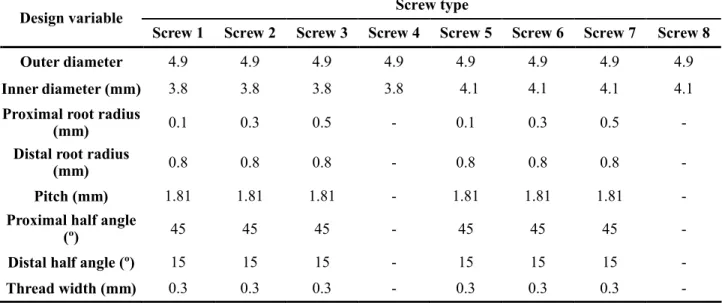
TABLE 1. Geometry and Dimensions of Locking Screws
Screw type Design variable
Screw 1 Screw 2 Screw 3 Screw 4 Screw 5 Screw 6 Screw 7 Screw 8 Outer diameter 4.9 4.9 4.9 4.9 4.9 4.9 4.9 4.9
Inner diameter (mm) 3.8 3.8 3.8 3.8 4.1 4.1 4.1 4.1
Proximal root radius
(mm) 0.1 0.3 0.5 - 0.1 0.3 0.5 -Distal root radius
(mm) 0.8 0.8 0.8 - 0.8 0.8 0.8 -Pitch (mm) 1.81 1.81 1.81 - 1.81 1.81 1.81
-Proximal half angle
(º) 45 45 45 - 45 45 45 -Distal half angle (º) 15 15 15 - 15 15 15
-TABLE 2. Geometry and Dimensions of Locked Nails
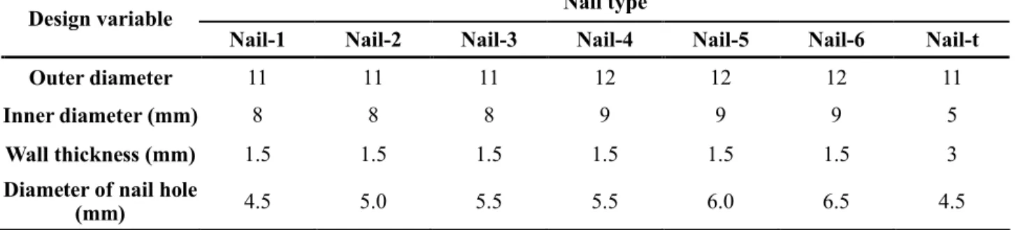
Nail type Design variable
Nail-1 Nail-2 Nail-3 Nail-4 Nail-5 Nail-6 Nail-t Outer diameter 11 11 11 12 12 12 11
Inner diameter (mm) 8 8 8 9 9 9 5
Wall thickness (mm) 1.5 1.5 1.5 1.5 1.5 1.5 3
Diameter of nail hole
(mm) 4.5 5.0 5.5 5.5 6.0 6.5 4.5
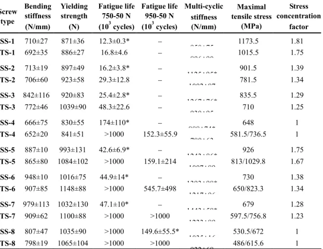
TABLE 3. Results of Mechanical Tests and Finite Element Analyses of Locking Screws Screw type Bending stiffness (N/mm) Yielding strength (N) Fatigue life 750-50 N (103 cycles) Fatigue life 950-50 N (103 cycles) Multi-cyclic stiffness (N/mm) Maximal tensile stress (MPa) Stress concentration factor SS-1 710±27 871±36 12.3±0.3* 950±75 1173.5 1.81 TS-1 692±35 886±27 16.8±4.6 896±90 1015.5 1.75 SS-2 713±19 897±49 16.2±3.8* 1125±95* 901.5 1.39 TS-2 706±60 923±58 29.3±12.8 1002±87 781.5 1.34 SS-3 842±116 920±83 25.4±2.8* 1267±76* 835.5 1.29 TS-3 772±46 1039±90 48.3±22.6 930±95 710 1.25 SS-4 666±75 830±55 174±110* 888±74* 648 1 TS-4 652±20 841±51 >1000 152.3±55.9 780±63 581.5/736.5 1 SS-5 887±10 993±131 42.6±6.9* 1243±86* 926 1.75 TS-5 865±80 1084±102 >1000 159.1±214 1007±89 813/1029.8 1.67 SS-6 948±10 1016±75 44.9±14* 1393±98* 730 1.38 TS-6 907±85 1148±88 >1000 545.7±498 1217±96 650/823.3 1.34 SS-7 979±113 1032±130 47.1±10* 1443±58* 679 1.28 TS-7 909±62 1100±88 >1000 >1000 1233±89 597.5/756.8 1.23 SS-8 807±47 1035±90 >1000 149.6±55.5* 1035±16 530.5/672 1 TS-8 798±19 1065±104 >1000 >1000 922±68 486/615.6 1
SS: stainless steel screw; TS: titanium screw; values expressed as mean±standard deviation; *statistically significant difference between SS and TS; /: stress under 200 N/ stress under 250 N.
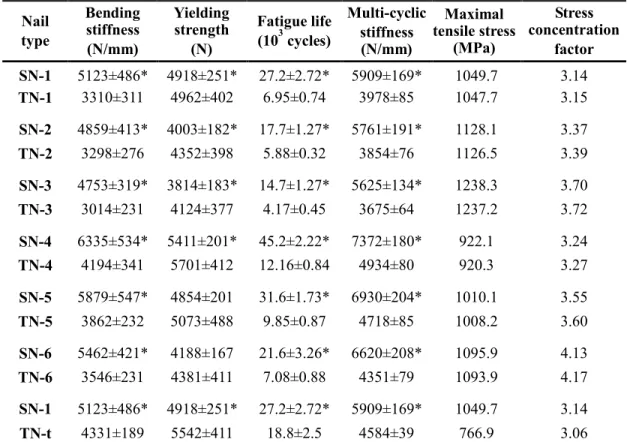
TABLE 4. Results of Mechanical Tests and Finite Element Analyses of Locked Nails Nail type Bending stiffness (N/mm) Yielding strength (N) Fatigue life (103 cycles) Multi-cyclic stiffness (N/mm) Maximal tensile stress (MPa) Stress concentration factor SN-1 5123±486* 4918±251* 27.2±2.72* 5909±169* 1049.7 3.14 TN-1 3310±311 4962±402 6.95±0.74 3978±85 1047.7 3.15 SN-2 4859±413* 4003±182* 17.7±1.27* 5761±191* 1128.1 3.37 TN-2 3298±276 4352±398 5.88±0.32 3854±76 1126.5 3.39 SN-3 4753±319* 3814±183* 14.7±1.27* 5625±134* 1238.3 3.70 TN-3 3014±231 4124±377 4.17±0.45 3675±64 1237.2 3.72 SN-4 6335±534* 5411±201* 45.2±2.22* 7372±180* 922.1 3.24 TN-4 4194±341 5701±412 12.16±0.84 4934±80 920.3 3.27 SN-5 5879±547* 4854±201 31.6±1.73* 6930±204* 1010.1 3.55 TN-5 3862±232 5073±488 9.85±0.87 4718±85 1008.2 3.60 SN-6 5462±421* 4188±167 21.6±3.26* 6620±208* 1095.9 4.13 TN-6 3546±231 4381±411 7.08±0.88 4351±79 1093.9 4.17 SN-1 5123±486* 4918±251* 27.2±2.72* 5909±169* 1049.7 3.14 TN-t 4331±189 5542±411 18.8±2.5 4584±39 766.9 3.06
SN: stainless steel nail; TN: titanium nail; values express as mean±standard deviation; * statistically significant difference between SN and TN.