Study on optimization of process parameters for hydromechanical deep
drawing of trapezoid cup
Thanh-Phong Dao, Shyh-Chour Huang*
Department of Mechanical Engineering National Kaohsiung University of Applied Sciences
Kaohsiung, Taiwan, R.O.C. E-mail: [email protected]
Abstract
Optimization the process parameters in hydromechanical deep drawing (HDD) of trapezoid cup is an important task for reducing production cost. To determine the optimum values of the process parameters, it is essential to determine their influence on the deformation behavior of the sheet metal. The most important process parameters for affecting thickness distribution of a trapezoid cup, namely punch speed, chamber pressure and friction coefficient, were determined. The Finite element method (FEM) combined with the Taguchi method served as a predictive tool to determine the influence parameters. FEM and the Taguchi method were used to identify the influence of each parameter considered in this study. The simulation was carried out with an orthogonal array (L9) of the Taguchi method. Based on analysis signal to noise and analysis of variance tests, it was found that optimal values of parameters are pressure at level 2 (8.5 MPa), friction coefficient at level 1 (0.005) and punch speed at level 2 (7500 m/s). Among these factors, friction efficiency has the greatest effect on thickness distribution in the HDD of the trapezoid cup.
Keywords: Hydromechanical deep drawing; Optimization; Finite element method; Taguchi method.
1. Introduction
One of the most important formative processes of sheet metal parts in manufacturing industries is hydromechanical deep drawing (HDD). The HDD process is a technique/tool which is often applied to fabricate hollow sheet metal parts with high drawing ratios or complicated shapes. The HDD is developed from conventional deep drawing. In HDD, the lower die set includes a drawing ring mounted on a pressure chamber in this process. The pressure chamber is filled with a hydraulic fluid. The punch acts as a mechanical press on the blank in terms of chamber pressure; therefore, the blank is deformed. The penetration of the punch into the hydraulic medium causes a pressure increase due to fluid compression that is controlled by the use of a pressure control valve. Friction between the punch and blank is raised because the blank is pressed firmly onto the punch due to pressure build up. As a result, higher forces, as compared to that in conventional deep drawing, can be transferred to the deformation zone. S.H. Zhang et al. [1] described when the HDD process is compared to the conventional deep drawing process, the limit drawing ratio (LDR) can be increased from 1.8 to 2.8, the tool costs can be decreased remarkably as only one tool half (the punch) is used; the female die is replaced with the chamber fluid, and only the punch needs to be varied when drawing parts with different shapes or dimensions. The formed parts have a more uniform thickness and better surface quality.
L. Lang et al. [2] simulated and experimented for some different cups with uniform pressure onto the blank ©2011 National Kaohsiung University of Applied Sciences, ISSN 1813-3851
by using HDD process. Their results showed that with material AL–Mg–Si alloy, a cup with drawing ratio of 2.46 was reached and a cup with a drawing ratio of 2.54 was drawn, but there is a heavy body wrinkling appeared. They also found that the thickness distribution is significantly effected by the liquid pressure variation. Moreover, the results showed that some typical failure modes such as the V-type fracture, tears of the blank flange and heavy body wrinkling exist in this process. In other study, L. Lang et al. [3] discussed about the effect of the process parameters on forming of two parts in aircraft manufacturing with typical aluminum material (2B06). The results indicated that the forming process significantly is influenced by the blank shape and the pressure in the die cavity. And the optimization of both the blank shape and the pressure the part can be formed successfully. Usually, the optimized pressure in the die cavity should be within 15 - 30 MPa for forming of typical aluminum material part (2B06).
In this study, an approach based on the finite element method combined with the Taguchi method is used to determine the most important process parameters (punch speed, chamber pressure, and friction coefficient) for affecting thickness distribution of a trapezoid cup. In HDD system, the components include the blank, blank holder, chamber pressure (female die), and punch as shown in Fig. 1 [4].
The paper is organized in the following manner. The Taguchi method is introduced first. The simulation details of using finite element method to determine analyze the process parameters are described next. Then, the parameter design using Taguchi method is introduced. Finally, the paper concludes with a summary of this study.
Fig. 1: Schematic illustration of the hydromechanical deep drawing system [4]
2. Taguchi method
M. Nalbant et al. [5] described that Taguchi method is applied for designed experiment. This approach has applied firstly in design of experiment of the exclusive world of the statistician and then, it has used more widely into the field of manufacturing. Taguchi method suggested that engineering optimization of a process or product should be carried out in three step approaches, i.e., system design, parameter design, and tolerance design. First of all, in system design, by using a scientific and engineering knowledge to make a basis functional prototype design, this design includes the product design stage and the process design stage. In the product design stage, the selection of materials, components, experimental product parameter values, etc., are involved. As to the process design stage, the analysis of processing sequences, these selections of production equipment, tentative process parameter values, etc., are involved. Since system design is an initial functional design, it may be far from optimum in terms of quality and cost.
The parameter design is used to optimize the settings of the process parameter values for improving performance characteristics and to identify the product parameter values under the optimal process parameter values. Moreover, it is expected that the optimal process parameter values obtained from the parameter design are insensitive to the variation of environmental condition and other noise factors. Therefore, the parameter design is the key step in the Taguchi method to achieving high quality without increasing cost.
Developed by Fisher [6], the basic classical parameter design is complicated and difficult to use. In particular, when the number of process parameters increases, a large number of experiments are required; the Taguchi method uses a special design of orthogonal arrays to study the entire parameter space with only a small number of experiments required. A loss function is then defined to calculate the deviation between the experimental value and the desired value. Taguchi recommends the use of the loss function to measure the performance characteristic deviating from the desired value. The value of the loss function is further transformed into a signal to noise (S/N) ratio η.
In the analysis of signal to noise, three categories of the performance characteristics are often used: the lower the better, the higher the better, and the nominal the better. The S/N ratio for each level of process parameters is computed based on the S/N analysis. Regardless of the category of the performance characteristic, the larger S/N ratio corresponds to the better performance characteristic. Therefore, the optimal level of the process parameters is the level with the highest S/N ratio η. Moreover, statistical analysis of variance (ANOVA) is applied to see which process parameters are statistically significant. With the S/N and ANOVA analyses, the optimal combination of the process parameters can be predicted. Finally, a confirmation experiment is conducted to verify the optimal process parameters obtained from the parameter design.
Using parameter design of the Taguchi method to optimize a process with multiple performance characteristics includes the: select process parameters to be evaluated; determination the number of levels for the process parameters; selection orthogonal array; calculation the S/N ratio; using the S/N ratio and ANOVA to analyze the experimental results; verification the optimal process parameters by confirmation experiment. Then, three objectives can be achieved through the parameter design of the Taguchi method, i.e: determination of the optimal design parameters for a process or a product; estimation of each design parameter to the contribution of the quality characteristics; and prediction of the quality characteristics based on the optimal design parameters. In this study, Taguchi method of experimental design was used to plan the numerical simulations.
3. Simulation of Hydromechanical Deep Drawing of Trapezoid Cup
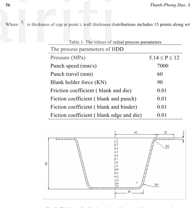
The formability of blank sheet depends on the process parameters such as pressure, punch speed, friction coefficient, and blank holder force. Fracture and wrinkle are the major modes of failure in sheet metal parts. Hence, using proper process parameters are essential to restrict wrinkling tendency and avoid tearing. One of the quality criterions in sheet metal formed parts is thickness distribution. In this study, a trapezoid cup with mild steel (DQSK) and blank thick of 1 mm is simulated by using Dynafor-3D to study the effect of these parameters on failure modes and thickness distribution. The parameters for simulation are shown in Table 1. Locations of measurement the wall thickness distribution of trapezoid cup are shown as Fig. 2. The mean of thickness distribution can be calculated as following:
15 1 M i i
T
t
==
∑
(1)
Where
t
i is thickness of cup at point i, wall thickness distributions includes 15 points along with cup center line.Table 1: The values of initial process parameters
The process parameters of HDD
Pressure (MPa)
5.14 ≤ P ≤ 12
Punch speed (mm/s)
7000
Punch travel (mm)
60
Blank holder force (KN)
90
Friction coefficient ( blank and die)
0.01
Fiction coefficient ( blank and punch)
0.01
Fiction coefficient ( blank and binder)
0.01
Fiction coefficient ( blank edge and die)
0.01
Fig. 2: Thickness distribution along with trapezoid cup center (unit:mm)
3.1 Effect of the Pressure in the Die Cavity on Wall Thickness Distribution
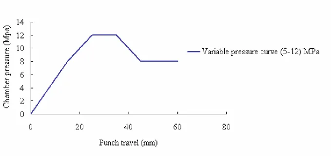
To study the influences of the pressure on wall thickness distribution, the simulation process was carried out with the four different variable pressure curves in the range from 5 to 12 MPa, one variable pressure curve in the range from 12 to 30 MPa and constant pressure values of 5MPa, and 12 MPa, as shown in Fig. 3, while other parameters have constant values, as shown in Table 1.
Fig. 3: Pressure loading using for simulation HDD of trapezoid cup
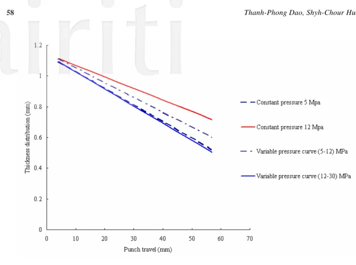
A comparison between wall thicknesses distributions of cup after analysis of simulation results, as shown in Fig. 4. When the pressure in the die cavity was 5 MPa, the thickness distribution along with cup center line was non-uniform. It can be found that when pressure in the die cavity is low, the wall thickness distribution is unevenly along with forming direction; the thinnest part is at the body of the cup. With high pressure of 12 MPa, thickness distribution was quite even along with forming direction; the thinnest regions were at the body of the cup. By using four variable pressure curves in the range value from 5 to 12 MPa, thickness distribution of cup in four of these cases had the same a value. The results showed that the wall thickness distribution by using constant pressure of 12 MPa is more even than using variable pressure in the range from 5 to 12MPa and variable pressure in the range from 12 to 30 MPa.
Fig. 4: Thickness distribution of trapezoid cup along with its center
Also, the results showed that wall thinning occurs at the bottom of the cup and thickening occurs near the top and at the flange. Near the top of the cup section and at the flange, blank thickening occurs due to the friction at the die and blank interface and the circumferential forces.
3.2 Effect of the Pressure on Wrinkling and Fracture of Formed Cup
Fig. 5 illustrates four cases of forming limiting diagram of a trapezoid cup. When pressure in the die cavity was 5 MPa, wrinkling appeared close to the die entrance radius and fracture could occur. It shows that when the pressure is too low, there will be a risk of cracking at bottom the body of the cup. At the pressure of 12 MPa, fractures could appear; wrinkling occurred around the body of the cup below the die entrance corner radius; and the body of the cup was unevenly formed. Using variable pressure in the die cavity from 5 to 12 MPa, shape of the product was better and without failures. The cup was formed according to desired shape. Using variable pressure in the range from 12 to 30 MPa, fractures occurred at bottom of the body of product.
a. Constant pressure 5 MPa b. Constant pressure 12 MPa
c.Variable pressure (5-12) MPa d. Variable pressure (12-30) MPa Fig. 5: Forming limitation diagram of trapezoid cup
3.3 Effect of Friction Coefficient on the Wrinkling and Fracture of Trapezoid Cup
To analyze the effect of friction coefficient on the HDD process, the experiment simulated some friction coefficients, such as: 0.005, 0.01 and 0.02 while other parameters have constant values, as in Table 1 and loading path is a variable pressure in the range from 5 to 12 MPa, as shown in Fig. 6.
Fig. 6: Variable pressure loading
Fig. 7 illustrated the results of three cases of the friction coefficients. From Fig. 7, we can see when the friction coefficient was equal to 0.02, cracking occurred at bottom of the body of the cup. When the friction coefficient was 0.005 and 0.01 there was no wrinkling and fracturing, the trapezoid cup would be formed successfully. It found that the friction coefficient is more than 0.01, fracturing and wrinkling will appear around body of cup. The friction coefficient is less than 0.005, lubrication will be more difficult, but there is no cracking and wrinkling, so the friction coefficient should be used in the range from 0.005 to 0.01 in the HDD of trapezoid cup.
The results show that friction is a key parameter in the HDD process of the trapezoid cup. To control friction coefficient between interfaces of parts, choosing a lubricant with consideration for temperature range of it, corrosion characteristics of material and the approaches of applying and removing the lubricant.
References
[1] Zhang S.H., Jensen M.R., Nielsen K.B., Danckert J., Lang b L.H., Kang D.C., “Effect of anisotropy and prebulging on hydromechanical deep drawing of mild steel cups”, Journal of Materials Processing Technology Volume 142, Issue 2, 25 November, Pages 544-550, 2003.
[2] Lihui Lang , Joachim Danckert, Karl Brian Nielsen, “Study on hydromechanical deep drawing with uniform pressure onto the blank”, International Journal of Machine Tools and Manufacture Volume 44, Issue 5, April, Pages 495-502, 2004. [3] Lihui Lang, Tao Li, Dongyang Ana, Cailou Chi, Karl Brian Nielsen, Joachim Danckertb, “Investigation into
hydromechanical deep drawing of aluminum alloy complicated components in aircraft manufacturing”, Materials Science and Engineering: A Volume 499, Issues 1-2, 15 January, Pages 320-324, 2009.
[4] Zhang S.H., Nielsen K.B., Danckert J., Kang D.C., Lang L.H., “Finite element analysis of the hydromechanical deep-drawing process of tapered rectangular boxes”, Journal of Materials Processing Technology Volume 102, Issues 1-3, 15 May, Pages 1-8, 2000.
[5] Nalbant M. , Gokkaya H., Sur G., “Application of Taguchi method in the optimization of cutting parameters for surface roughness in turning”, Materials Volume 28, Issue 4, Pages 1379-1385, 2007.
[6] Fisher R.A., Statistical methods for research worker, London: Oliver & Boyd, 1925.
![Fig. 1: Schematic illustration of the hydromechanical deep drawing system [4]](https://thumb-ap.123doks.com/thumbv2/9libinfo/8826168.233993/2.892.252.623.617.804/fig-schematic-illustration-hydromechanical-deep-drawing.webp)