國
立
交
通
大
學
資訊學院 資訊學程
碩
士
論
文
在 TinyOS 上實現 TDMA 機制
Implementing a TDMA Mechanism on TinyOS
研 究 生:陳春華
指導教授:曾煜棋 教授
在 TinyOS 上實現 TDMA 機制
Implementing a TDMA Mechanism on TinyOS
研 究 生:陳春華 Student:Chun-Hua Chen
指導教授:曾煜棋 Advisor:Yu-Chee Tseng
國 立 交 通 大 學
資訊學院 資訊學程
碩 士 論 文
A ThesisSubmitted to College of Computer Science National Chiao Tung University in partial Fulfillment of the Requirements
for the Degree of Master of Science
in
Computer Science July 2008
Hsinchu, Taiwan, Republic of China
在 TinyOS 上實現 TDMA 機制
學生:陳春華
指導教授
:曾煜棋
國 立 交 通 大 學 資 訊 學 院 資 訊 學 程 碩 士 班
摘
要
現今無線感測網路在各種領域都有相當廣泛的應用,TinyOS 是無線感
測網路中相當常見的作業系統。由於此系統的底層為 CSMA-CA 機制,
所以當網路流量擁擠時,封包彼此干擾或是碰撞情形亦相對嚴重,在
封包重新傳送的過程,意味著感測器額外電池電力消耗。在本篇論文
中,我們將嘗試將 TDMA 機制加到 TinyOS 作業系統中,硬體方面則
選用 Micaz。在 TDMA 系統中,每顆感測器都將在其擁有的時間區段
內傳輸資料,如此將可避免因為封包干擾或碰撞而導致的封包重新傳
送。實作元件分別為系統時間同步、感測器時間區段分配、低耗電機
制。同時,當感測器進入省電模式時,其無線模組界面亦會關閉,藉
此達到省電效果。最後,在實驗中亦可以驗證系統時間同步有相當的
準確度與穩定性,這對維持 TDMA 運作的穩定性來說是相當重要的因
素。
Implementing a TDMA Mechanism on TinyOS
Student:Chun-Hua Chen
Advisors:Dr. Yu-Chee Tseng
Degree Program of Computer Science
National Chiao Tung University
ABSTRACT
Wireless sensor network (WSN) is widespread in several different
application fields now. In WSN, TinyOS is the most popular operating
system. TinyOS adopts CSMA-CA mechanism in its MAC layer. When the
network with heavy traffic loads, packets collision and interference will be
more serious. When packets collision happened, sensor nodes will do
packets retransmission and consume additional power. In this thesis, we try
to implement TDMA mechanism in TinsOS with platform Micaz. TDMA
mechanism can resolve the problem of packets collision because each
sensor node has its time slot and data will be transmitted in the assigned
time slot. We implement the components include time synchronization, slot
assignment algorithm and power saving mechanism. When a sensor node
enters power saving mode, program process will also disable radio
interface for power saving. Time synchronization one of the important
factor for TDMA mechanism and experiment result shows our time
synchronization algorithm can work over many hours with accuracy and
stability.
誌
謝
身為在職專班學生,除了白天時間上班之外,夜晚或是假日也必
須上課或進行相關研究。這種工作與學業都必須兼顧的情況,除了自
身的堅持之外,同時也需要指導教授、家人以及公司方面的支持。
首先特別感謝指導教授曾煜棋老師在我整個研究方向與論文方面
的指導,使我能夠專注在無線網路的研究而不至於偏離主題。其次,
感謝已經畢業的博士生致宇,在我遇到困難時都能提供協助,不論程
式或是觀念,每次聊天過後都讓我有所突破。還有同組的書賢、亭瑩,
雖然彼此聊天不多,但是感謝你們在最後口試前提供的意見。
同時也要感謝家中的幾隻貓狗,每當夜深人靜,我埋首於書桌前,
它們總是默默在一旁陪伴。最後感謝我的妻子家鳳以及小孩柏融,在
這段期間容忍我不安的情緒,處理家中所有大小雜事,讓我能夠心無
旁鶩完成學業。
在此也期許自己未來面對任何挑戰,能夠繼續保有不輕易放棄的精
神與態度,感謝所有幫助過我的一切事物。
Abstract (in Chinese) ... i
Abstract (in English) ... ii
Acknowledgement (in Chinese)...iii
Contents... iv
List of Tables ... vi
List of Figures ...vii
1. Introduction ... 1
1.1 Overview of Wireless Sensor Network... 1
2. Related Works ... 2
2.1 Motivation ... 2
2.2 Related papers research... 2
2.2.1 Time synchronization:... 2
2.2.2 Slot assignment: ... 6
3. Hardware and Operating System ... 9
3.1 Sensor board:... 9
3.1.1 Sensor board:... 9
3.1.2 Mote Interface Board (MIB):... 9
3.1.3 Mote Processor Radio (MPR):... 10
3.2 TinyOS ... 11
3.3 NesC ... 12
4. System Architecture to Realize TDMA ... 15
4.1 System architecture ... 15
4.1.1 Fame structure... 15
4.1.2 Software components architecture ... 17
4.2 Time synchronization ... 18
4.2.1 Overview ... 18
4.2.2 Implementation detail ... 19
4.3.1 Overview ... 21
4.3.2 Implementation detail ... 22
4.4 Mode selection mechanism... 25
4.4.1 Transmission Operation ... 28
4.4.1.1 Overview ... 28
4.4.1.2 Implementation detail ... 28
4.4.2 Basic Receipt Operation ... 30
4.4.2.1 Overview ... 30
4.4.2.2 Implement ... 30
4.4.3. Idle Operation ... 31
4.4.3.1 Overview ... 31
4.4.3.2 Implementation detail ... 32
5. Experiment... 35
5.1 Time Synchronization Algorithm... 35
5.2 Slot Assignment ... 38
5.3 Current Consumption ... 39
6. Conclusions and Future Works... 41
List Of Tables:
Table 3-1. Relation between provide and use interface. ... 13
Table 4-1. Several packet types in slot assignment... 23
Table 4-2. Sleep mode for ATmega128... 32
Table 5-1. Motes slot number list... 39
List Of Figures:
Figure 2-1. (a) Standard critical path (b) RBS critical path... 4
Figure 2-2. Level discovery and level values in TPSN. ... 5
Figure 2-3. Calculated clock offset in TPSN.. ... 6
Figure 2-4. Example of slot assignment algorithm... 7
Figure 2-5. Successful round for receiving grant message... 8
Figure 2-6. Failed round for receiving reject message. ... 8
Figure 3-1. MTS310 and MIB510 ... 10
Figure 3-2. MPR2400 and Block Diagram ... 10
Figure 3-3. Example for wiring modules. ... 14
Figure 4-1. TDMA mechanism overview, N modes in network... 17
Figure 4-2. Components Architecture... 18
Figure 4-3. IEEE 802.15.4 packet format. ... 19
Figure 4-4. Timestamp with the SFD (a) sending packet (b) receiving packet
... 20
Figure 4-5. (a) One hop neighbor link list (b) Mixed hop neighbor link list
... 22
Figure 4-6. Build up mixed hop neighbor link list. ... 25
Figure 4-7. Mode selection mechanism ... 26
Figure 4-8. Time slot and interrupt ... 26
Figure 4-9. Set hardware timer in ATmega128... 28
Figure 4-10. AM message packet format ... 29
Figure 4-11. Flow chart for transmission operation... 30
Figure 4-12. ATmega128 Clock Distribution... 31
Figure 4-13. Interfaces relations for power saving mode. ... 34
Figure 5-1. Time synchronization environment... 35
Figure 5-2. Time synchronization test results. ... 36
Figure 5-4. Two-hop time synchronization test results... 38
Figure 5-5. Slot assignment environment ... 39
Figure 5-6. Current consumption test environment ... 40
Chapter 1
Introduction
1.1 Overview of Wireless Sensor Network
Wireless Sensor Network (WSN) [1] has become a very popular technology and research area in recent years. WSN systems are composed of many power-limited and small size sensor nodes distributed deployed over indoor or outdoor environment. People use this technology on several fields [2], [3] such as remote environment monitoring, military surveillance, health monitor and target motion tracking. When the sensors monitor and detect events happened in their sensing region, the sensed data will be transferred to the sink. Users can retrieve useful data form sink then analyze it and do the corresponded actions. A wireless sensor node is the embedded system inside; it consists of processor unit, storage unit, one or more sensor units and low-power transceiver unit.
The following chapters will describe this thesis in detail. Chapter 2 describes our motivation and related research in time synchronization and slot assignment. In Chapter 3, it describes the detail information of software and hardware platform. In Chapter 4, we present the basic concepts of time synchronization, slot assignment, packet transmission and power saving. We also explain how to implement new components for this project. Chapter 5 shows how to do the experimental and testing results. Chapter 6 describes conclusion and future works of this thesis.
Chapter 2
Related Works
2.1. Motivation
TinyOS [4] is a popular operating system in WSN and it adapts B-MAC [5] as its MAC layer protocol. B-MAC is base on of CSMA-CA [6] mechanism and there are some drawbacks for this mechanism obviously. The major disadvantage of CSMA-CA is packets collision can not be avoided. When the network traffic is heavier, the packets collision will be more serious. Under this situation, more packets will be re-transmitted and the transmission nodes will consume more power. There also has two hop neighbors hidden terminal problem because the carrier sensing does not work beyond one hop distance. Although RTS/CTS [6] policy can resolve hidden terminal problem but it will cause more overhead in the system.
TDMA is one of the solutions for above problems because each node has its own time slot and send packet in different time slot. It could avoid packet collision and no hidden terminal problem. The goal of this thesis is to implement the TDMA mechanism in TinyOS. We will focus on time synchronization, slot assignment, packet transmission, packet receipt and power consumption. We will modify and add some components in TinyOS with Micaz platform. It is useful for us to research hardware abstraction layer in the future.
2.2. Related Works
2.2.1. Time synchronization
In TDMA mechanism, accurate time synchronization is needed. There are some limitations in WSN and the time synchronization methods [7], [8], [9], [10] are different than wired system. When the packets from sender to receiver, there are some factors will be varied and uncertain. We list some factors as below.
mote is powered on at different time.
z Clock drift: The crystal frequency differences between system nodes. It is because of manufactured crystal tolerance.
z Send time: Sender node program calls system APIs to constructs message and put it on the radio interface. It depends on current system and processor loading.
z Access time: Message in radio buffer and waits to access transmit channel.
z Interrupt handle time: Delay between the radio chip raising and the microcontroller responding to an interrupt.
z Encoding time: Sender node radio chip to encode and transform binary data messages into electromagnetic waves.
z Transmission Time: depending on the length of the message and the speed of the radio media.
z Propagation time: Time spent for transmitting message from sender to receiver. z Decoding time: Receiver node radio chip will transform and decode message from
electromagnetic waves into binary data.
z Receive time: Receiver node program will be notified that message had been arrived already.
We will review two time synchronization approaches in WSN:
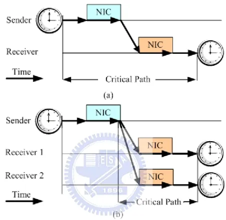
Reference Broadcast Synchronization (RBS) [7]: Instead of synchronizing the sender with a receiver, RBS synchronizes a set of receivers with one another. A transmitter broadcasts a reference packet to two receivers and each receiver records the time for receiving reference packet. Then receivers exchange their observation time then calculate clock offset between the nodes. For high precision demand, it can increase the number of reference packets then average the values of clock offset.
This scheme has the following advantage:
z Completely eliminating transmitter side uncertainties. The critical path will be changed and eliminate sender’s send and access time. Figure 2-1 shows the differences between standard critical path and RBS critical path.
This scheme has the following disadvantages: z Number of messages exchange is high.
z For n nodes, one node broadcasts the reference packet and n-1 messages exchange for time synchronization. There are more network traffic overhead and high energy consumption in system and nodes.
Figure 2-1. (a) Standard critical path (b) RBS critical path
Timing-sync protocol for sensor networks (TPSN) [8]: This algorithm includes level discovery phase and synchronization phase.
When the system in level discovery phase, it will do the following steps.
z Sink node is selected as the root node and broadcasts discovery packet. The packet contains node level value and local node id. Level value denotes the hop counts from sink.
z When nodes receiving discovery packets, nodes will record the source packet’s node id as parent id then rebroadcast discovery packets with local node id and new level value. When nodes receiving several discovery packets, nodes will accept packet with smallest level value and update their level values.
z When all the nodes know their level values and parents node id, it means the level discovery procedure is completed.
The parent-child tree is shown in Figure 2-2 and the label numbers represent node’s level values.
Figure 2-2. Level discovery and level values in TPSN. When the system in synchronization phase, it will do the following steps. z Using two-way messages exchange.
z Child node initiates synchronization by sending the synchronization message which includes node’s level value and timestamp.
z Parent node receives synchronization message and replies an acknowledge message which includes timestamp.
z Child node will calculates clock offset and propagation delay then it will synchronize its system time with parent node.
Figure 2-3. Calculated clock offset in TPSN. This scheme has the following advantages:
z The protocol is scaleable when the size of network is increased. z It is more accuracy than RBS.
This scheme has the following disadvantage:
z TPSN is a hierarchical topology and it is not suitable for highly mobile nodes. 2.2.2. Slot assignment
In TDMA system, each node should have its own time slot and transmits packets in the pre-scheduled time slot. We will introduce some slot assignment algorithms [11], [12], [13] which are related to WSNs.
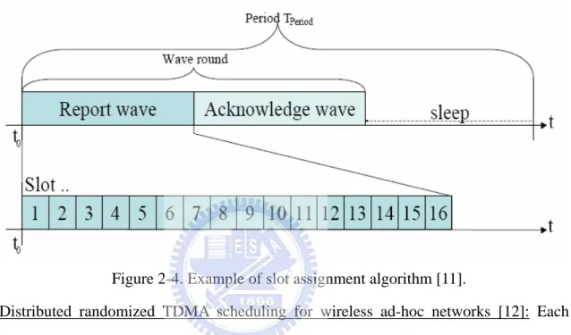
Wireless Fire Sensor Network Demonstrator [11]: This slot assignment algorithm is composed of report wave phase and acknowledge wave phase.
z In report wave: Each node will send its aggregated alive information in the assigned slot when the system in report wave phase. After system report wave has finished, the sink initiates system acknowledge wave. If all registered nodes are reported, the whole network will enter sleep mode.
z Network slot schedule is calculated at the sink then it propagates the needed information through acknowledge wave. There are some rules for slot assignment. Nodes with the higher hop counts to the sink have earlier slots assigned.
is random.
The slot numbers are assigned contiguous from the latest slot number towards to the earliest slot number.
z In acknowledge wave: Sink propagates slot number for each node.
Figure 2-4 shows one example for a network which consists of N = 16 nodes and every wave is divided into N slots.
Figure 2-4. Example of slot assignment algorithm [11].
Distributed randomized TDMA scheduling for wireless ad-hoc networks [12]: Each node maintains its state machine and there are four states: IDLE, REQUEST, GRANT and RELEASE. The DRAND algorithm runs by rounds and the main procedures as following.
z Node A into REQUEST state and broadcasts request message to its one-hop neighbors.
z Neighbor B receives a request from A. When node B is in IDLE or RELEASE state then it changes into the GRANT state and sends a grant message to node A. When node B is in the REQUEST or GRANT state then node B sends a reject message to node A.
z When node A receiving the grant packets from its entire one-hop neighbors for responding request packer, it decides on its time slot to be the minimum of the time slots that have not been taken by its two-hop neighbors before this round. Then node
A enters the RELEASE state and broadcasts a release message which contains information about its selected time slot to its one-hop neighbors.
z When node A receiving a reject from any node then node A sends a fail message to all its one-hop neighbors and changes its state to the IDLE state.
Figure 2-5 shows successful round where node A decides on a time slot after it receives grant messagess from all of its one-hop neighbors. Figure 2-6 shows failed round because node B has sent a grant message to another one-hop neighbor before receiving the request packet from node A.
Figure 2-5. Successful round for receiving grant message [12].
Chapter 3
Hardware and Operating System
In this chapter, we will introduce sensor node with hardware platform and operating system software aspects. We can see more information about hardware platform Micaz. For the software, TinyOS [4] is the most popular embedded operating system in WSN. We will review the basic mechanisms and features about it.
3.1 Micaz Motes
Micaz is one of the series products for WSNs. It is designed by UC Berkeley and produced by Crossbow Technology, Inc. Sensor board and interface board will integrate with Micaz for data sensing and program downloaded purpose.
3.1.1 Sensor board
MTS310 is a flexile sensor board with a variety of sensing modalities. These modalities include dual-axis accelerometer, dual-axis magnetometer, light, temperature, acoustic and sounder. The sensor detects physical world phenomena and produce analog signals to ADC.
3.1.2 Mote Interface Board (MIB)
MIB510 [14] allows for the aggregation of sensor network data on a PC as well as other standard computer platforms. This interface board includes serial port programming for IRIS, MICAz and MICA2 platforms. It also supports JTAG for code debugging.
The MIB510 has one system processor which is named Atmega16L on board. Code is downloaded to system processor through the RS-232 serial port. Then system processor programs the code into the mote. The system processor runs at a fixed baud rate of 115.2 k.
Figure 3-1. MTS310 and MIB510 3.1.3. Mote Processor Radio (MPR)
MPR2400 [14] is a 2.4 GHz mote module used for enabling low-power, wireless sensor networks. The key features of the platform as below.
z IEEE 802.15.4 compliant RF Transceiver Chipcon CC2420 [17].
z Microcontroller Atmel ATmega128L [16] with 128K Bytes in system flash. It contains analog inputs, digital I/O, I2C, SPI and UART interfaces.
z 250 kbps data rate.
z 2.4 to 2.48 GHz, a globally compatible ISM band and programmable in 1 MHz steps. z Indoor range up to 20 m or 30 m.
z Direct sequence spread spectrum radio which is resistant to RF interference and provides inherent data security.
3.2 TinyOS
TinyOS [4] is initially developed by the U.C. Berkeley EECS Department and it is a standard framework used in wireless embedded sensor networks. The components and interfaces are reusable.
TinyOS has several important features. It is a component-based architecture with simple event-based concurrency model and split-phase operations. We will descript these concepts by sequence later.
z Component-based architecture
TinyOS [18] contains several build-in components such as timer, ADC, LED and hardware control modules. Each program is composed of different components. There are two types of components, module and configuration. When upper application program wants to set up a periodical timer, it will include the related modules and these modules are wired together by configuration files. By this way, application can manipulate the needed modules by wiring method.
Each module component can provide or use interfaces. There are a set of functions declared in interfaces. When the module “provide” interface, it means the module must implement all of the declared functions in interfaces and these functions will be called by other module’s interfaces. When the module “use” interfaces, it means the module can call all of the declared functions in the interface. But the interface also has to prepare some callback functions which will be called by “provide” interface modules.
Briefly, modules will interact with others modules by interfaces. The advantage for this architecture is components reusable. For example, when one programmer has implemented the hardware ADC modules then the other programs also can use the related ADC functions by wiring ADC modules into current modules. When there are some problems in ADC component, the developer will focus on one module and there is no need to rewrite the whole program. When the known issues in ADC component are fixed then the related programs can work properly again. In this architecture, program looks like a chain of components and upper application does not need to know the detail
low level hardware behaviors. Each component will focus on its current scope. It will active and increase efficiency for software developing and debugging.
z Tasks and event-based concurrency
In TinyOS [18], there is no kernel-space, user-space and context switching. The standard scheduler of TinyOS [18] follows a FIFO policy to execute tasks, task runs to completion in background and could not be preempted by other tasks. But tasks could be preempted by interrupt handler event. Many events are triggered by hardware, such as timer, sending packets and receiving packets. When the task is preempted by hardware interrupt, it will face concurrency problem. The programmer must handle above situations and protect shared variables carefully.
In NesC [19], we can declare a section of codes with syntax “atomic” and it means current process should not be preempted by interrupts. Absolutely, we can use syntax “atomic” to protect shared variables in a task. Although above mechanism can do variables protection, it is better to keep tasks and atomic sections shorter. With shorter tasks, system will have faster reaction time to handle interrupt events.
z Split-phase operations
It is better to split long-latency operations into different phases. In a blocking system, the program calls a long running operation and the function does not return until the needed operation is complete. Obviously, the system will waste time for waiting and nothing can do. In a split-phase system, when the program calling a long running operation then the function returns immediately and CPU can do the other things. When the operation is completed, system will signal the corresponded callback function to remind current process. With this mechanism, it avoids blocking state in the system.
3.3 NesC
NesC [19] means Network Embedded System C and it is an extension type of the C language. All of the TinyOS operating system, libraries and applications are written in NesC. The basic concepts for NesC are listed as below.
z Code will be generated by program compilers.
It can increase runtime efficiency and robust design, so the components are statically linked to each other via their interfaces. It provided a better code generation and static analysis and it can detect data race at compile-time.
z Component behaviors are specified in a set of interfaces.
The provided interfaces are intended to represent the functionalities that the components provide to its user. The used interfaces used the functionalities that component needs to perform its job.
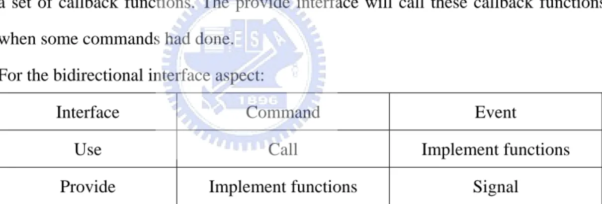
z Interfaces are bidirectional:
There are two kinds of interface, “provide” and “use” interface. Provide interface means components implement a set of functions, then other components can wire to the interfaces and used these functions. Use interface means components implement a set of callback functions. The provide interface will call these callback functions when some commands had done.
For the bidirectional interface aspect:
Interface Command Event
Use Call Implement functions
Provide Implement functions Signal
Table 3-1. Relation between provide and use interface.
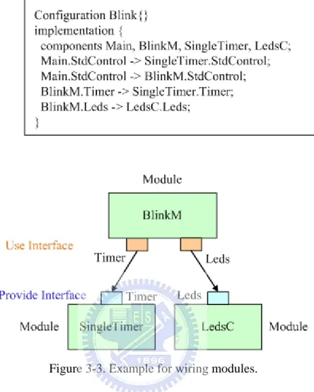
One example in Figure 3-3, it shows how the configuration files to wire modules together. Configuration wires modules BlinkM and SingleTimet by interface Timer and it also wires modules BlinkM and LedsC by interface Leds.
Chapter 4
System Architecture to Realize TDMA
In this chapter, we will introduce the components in TDMA mechanism and focus on components implementation. The goal is to design the suitable modules and use these modules to realize TDMA mechanism. The exported functions will be declared in interfaces then application layer programs can wire these modules together and use the provided functions.
4.1 System architecture
In this section, we will overview TDMA mechanism in two aspects. Fame structure is for system running time period and software components architecture is for the relation between components. There are three basic components in TDMA mechanism which includes time synchronization, slot assignment algorithm and mode selection.
4.1.1 Fame structure
The frame structure is composed of control phase and transmission phase. There are three types of periods: time synchronization period, slot assignment period and mode selection period. The overview of TDMA scheme is shown in Figure 4-1.
In control phase, each node will recognize and record its parent node then system will build up a parent-child forwarding tree. After each node has learned its parent node, system will do time synchronization (section 4.2) for each pair of parent and child nodes. In time synchronization period, each child node will send time synchronization packets to its parent node and parent node will send back acknowledge packets with timestamp. Then child node will depend on timestamp to calculate time offset then modifies its local time to match with parent node. When this period is completed, system will enter slot assignment period.
neighbor’s information through packets exchange then node will execute slot assignment algorithm (section 4.3). After executed the algorithm, every node in the system will get its slot number. Then each node sends packet to sink with its slot number through parent-child forwarding tree. Sink will receive all the reports from each node then sink calculates cycle length by this information. Finally, sink will broadcast packets with total cycle length inside.
In transmission phase, there is mode selection period inside. Mode selection period (section 4.4) will be divided into transmission operation, receipt operation and idle operation. After control phase completed, each node got its slot number. At the beginning of each time slot, node will enter one of above operation modes. When node owns current time slot, it will enter basic transmission operation and node can transmit packets in this time slot. When one of the node’s one-hop neighbors owns current time slot, node will enter basic receipt operation and wait for receiving packets from its neighbors. When current time slot is neither owned by the node nor by its one-hop neighbors then node will enter idle mode.
At the beginning, system enters control phase and each node executes time synchronization and slot assignment algorithm. Then system enters transmission phase after system nodes have synchronized with their parent nodes and get their own time slots. In transmission phase, system nodes will transmit and receive packets under TDMA mechanism for a long period of time. After a long time, system will enter control phase again. Then nodes will re-synchronize with their parent nodes and do slot assignment algorithm again.
Figure 4-1. TDMA mechanism overview, N modes in network 4.1.2 Software components architecture
In the thesis, we do not design new MAC layer protocol and physical interface. So the TDMA mechanism is still base on the B-MAC protocol. Actually, it works as the middleware between application layer program and low-level hardware. The relation between TDMA components and TinyOS’s components is shown in Figure 4-2. TDMA module will provide several interfaces then upper application will wire them and use the related commands or events.
Time synchronization, slot assignment algorithm and mode selection components will process packets transmission, packet receipt and message exchange. So these components will connect to TinyOS transmit and receive component groups. In these groups, active message component will provide interfaces with packet transmission and receipt for upper application. CC2420 related components will control the interrupt of packets sending and receiving, switch hardware into transmit mode or receive mode, read and write data from FIFO queue, RF power and so on.
Time synchronization component will connects to timestamp component group. In this group, time component provides system time and we use it for time synchronization. Mode selection component will connect to power management components group which will control ATmega128 in active, idle and other power saving modes. Power
management components also can turn on and turn off CC2420’s crystal oscillator. By this way, it can disable RF interface when the mote into idle mode.
TDMA Components Application HPLPowerManagement Power Management components CC2420ControlM TinyOS Application TinyOS Components TimeStamping TimeStamp component GenericComm Transmit and Receive components AMStandard
ATMEL ATmega128 Chipcon CC2420 Hardware CC2420RadioM HPLCC2420M Timer Slot Assignment Algorithm Time Synchronization Mode selection CC2420ControlM HPLCC2420FIFOM LoggerM
Figure 4-2. Components Architecture
4.2. Time synchronization
In TDMA architecture, time synchronization is an important topic because every system mote will power on at different time. Without accurate time synchronization, some motes will transmit packets at the same time. It will cause interference, packets collision and reduce the performance.
4.2.1. Overview
basic concepts in section 2.2.1. At the beginning of control phase, TPSN protocol is running. Child node will synchronize system time with its parent node and it can eliminate clock offset issue between itself and parent node. Actually, there are some uncertain factors in time synchronization. In TPSN, send time, access time and receive time are important because system posts task for packet transmission and signal receive event.
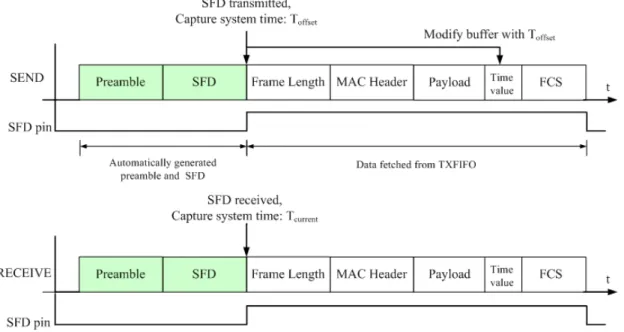
In Micaz platform, Chipcon CC2420 [17] will access 802.15.4 radio packet and it connected to ATmega128 through SPI interface. Packet format is shown in Figure 4-3. There is one pin which named “SFD” in Chipcon CC2420. SFD pin goes active when the start of frame delimiter (SFD) field in radio packet has been completely transmitted or radio packet’s SFD field in 802.15.4 [20] packet has been completely received.
For packet transmission [21], application layer program sent radio packets by posting a task. System will prepares packet header and payload then put this task into task FIFO queue. In the FIFO queue, task will be handled by sequence. It is not suitable to add timestamp in application layer. Because there must have uncertain time difference between calling system function and packet leaving radio interface. One better way is to add packet timestamp in MAC layer instead of adding it in application layer. For packet receipt, time difference still exist between packet arrived at MAC layer and application program been noticed to retrieve packet from receive buffer.
Figure 4-3. IEEE 802.15.4 packet format. 4.2.2. Implementation detail
For TPSN implementation, sink node will broadcast discovery packet in initial time. This packet contains level value and local node id. Nodes receive discovery packet
will record source node id as parent node id then re-broadcast it with increment level value by one. Nodes not receive discovery packet will broadcast request packet for getting level value. Any node receives request packet will send discovery packet to it.
For time synchronization, it is the two way packets exchange with timestamp. During synchronization, if there is no response from parent node, child node will send synchronization packet again. If it is still no response for several times, child node will send request packet then retrieve level value and parent node again. It is important not to add timestamp in application layer. In packet transmission procedure, sending system function will prepare packets and put them into Chipcon CC2420 TXFIFO buffer through module HPLCC2420FIFOM. During packet transmission, CC2420 SFD pin will active when the packet SFD field (start of frame delimiter) has been sent. It will trigger interrupt then we have to capture current system time and add timestamp in sending packet. Above procedures are implemented in interrupt handler. For packet receipt, packets will put in CC2420 RXFIFO. During this period, SFD pin will active when the packet SFD field has been received. We also capture current system time in the interrupt handler and record it as receipt time. Figure 4-4 shows the relation between timestamp and SFD pin.
During code implementation, something should be noticed:
z During packet transmission period, SFD interrupt is happened. It is important to generate timestamp and add it into packet as soon as possible. Otherwise, packet had been transmitted already and packet payload will not be modified.
z In time synchronization, there are many packets with different types such as level discover, time synchronization and synchronization acknowledge packets. It is a good idea to assign different type packet with different handle ID. The handle ID can be assigned in configuration files. TinyOS will dispatch these packets to the corresponded functions and it will be easier for code implementation and debugging. Reference to Figure 4.2, time synchronization operation uses all the components in “Transmit and Receive components” and “TimeStamping components”.
4.3. Slot assignment algorithm
4.3.1. Overview
In control phase, each mote can get its own slot number through slot assignment algorithm. We use node ID, request packets and grant packets to do slot assignment. Every node will maintain one-hop and mixed-hop neighbor link lists which include neighbor’s information such as node ID, node slot number and so on.
The main procedures of slot assignment algorithm as following:
z Mote X will collect its entire one-hop and two-hop neighbor’s information then build up one-hop and mix-hop neighbor link lists.
z According to mixed-hop neighbor link list, mote X will send slot request packets to all of its one-hop and two-hop neighbors.
z When mote Y received slot request packet from mote X.
If mote Y does not get its slot number yet and Y.id < X.id then mote Y will reply slot grant packet to mote X.
Otherwise, mote Y will do nothing.
z Once mote X receives all grant packets from its one-hop and two-hop neighbors then mote X will select one slot number which is not used by its one-hop and
two-hop neighbors.
z Mote X will send slot number grant packet to its one-hop and two-hop neighbors with selected slot number.
z Mote X will send packet to sink with selected slot number.
z Sink receives all of these packets from system nodes and calculates slot cycle length. z Finally, sink will broadcast packets with slot cycle length information.
4.3.2. Implementation detail
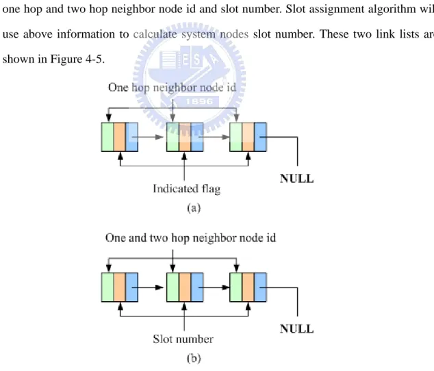
Each node will maintain one-hop and two-hop neighbor information. Because the numbers of neighbors are uncertain so we create two link lists. One-hop neighbor link list contains node’s one-hop neighbor node id. The link list will be used by other nodes to build up mixed-hop neighbor link list. Mixed-hop neighbor link list contains node’s one hop and two hop neighbor node id and slot number. Slot assignment algorithm will use above information to calculate system nodes slot number. These two link lists are shown in Figure 4-5.
Figure 4-5. (a) One-hop neighbor link list (b) Mixed-hop neighbor link list
In this section, there are several different packet types and we list some packet types as shown in Table 4-1. The following steps show how the slot assignment works.
Packet Type Description
One hop request packet Request for node’s one-hop neighbor.
One hop reply packet
One-hop neighbor replies to request node with node id.
One hop information packet
Node broadcasts all of its one-hop neighbors node id. Slot request packet Request for one / two-hop grant packet.
Slot grant packet Reply to request node with grant information.
Slot number grant packet
Node informs its one and two hop neighbor with selected slot number.
Slot number sink packet
Node informs sink with selected slot number. Table 4-1. Several packet types in slot assignment
First, node X will broadcast one hop request packets with node id. All of node X’s one hop neighbor nodes will receive these request packets then send one hop reply packets to node X. Node X will build up one-hop neighbor link list by these one hop reply packets. By the same way, node X’s one-hop neighbors also build up their one-hop neighbor link list.
Second, node X will broadcast one hop information packets which contains all of its one-hop neighbor nodes id and local node id. When node Y received these packets, it will know the entire two hop nodes id. By the same way, node X also knows the entire two hop nodes id. Node X will receive many one hop information packets from its one hop neighbors and it will filter out the redundant packets then build up the mixed hop neighbor link list.
Third, node X refers its mixed hop neighbor link list and sends slot request packets to its one hop and two hop neighbors with local node id. According to slot assignment algorithm (section 4.3.1), node X’s neighbors will send slot grant packets to node X when its nodes id are small than node X’s id.
grant packets are ready or not. After all of the grant packets are received, node X will select one slot number different than its neighbors. Node X will send slot number grant packets to its entire one hop and two hop neighbors. These nodes will modify their mixed hop neighbor link list.
Fifth, node X will send slot number sink packet to sink. Sink will calculate total slot cycle length and broadcast slot cycle length information.
According to slot assignment algorithm (section 4.3.1), node with largest id will collect the entire one hop and two hop neighbor’s grant packets earlier than the other nodes. So the node with largest id will select its slot number first the smallest id node will select its slot number at the end.
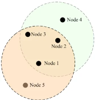
One example is shown in Figure 4-6. This example explains how to build up mixed hop neighbor link list.
z Node 1: One hop neighbor link list: {2, 3, 5} Node 2: One hop neighbor link list: {1, 3, 4}
z Node 1: Broadcast one hop information packet: {1, 2, 3, 5} Node 2: Broadcast one hop information packet: {2, 1, 3, 4} z Node 1: Received one hop information packet from node 2.
Builds up mixed neighbor link list: {2, 3, 4, 5} Node 2: Received one hop information packet from node 1.
Builds up mixed neighbor link list: {1, 3, 4, 5}
z Node 1: Knows node 4 is two-hop neighbor now. Node 1 will send slot request packet to node 4 later.
Node 2: Knows node 5 is two-hop neighbor now. Node 2 will send slot request packet to node 5 later.
Figure 4-6. Build up mixed hop neighbor link list.
In the real environment, radio interference and packet loss can not be avoided, so something should be noticed:
z When mote X broadcasts one hop request packet and it receives over two one hop reply packets from mote Y. Mote X will add mote Y in one-hop neighbor link list. z Mote X sends slot request packet to all of its one-hop and two-hop neighbors, when
packet timeout happened it will send request packet again.
Reference to Figure 4.2, slot assignment algorithm uses all the components in “Transmit and Receive components”.
4.4. Mode selection mechanism
After each node doing time synchronization with its parent node and getting its slot number (section 4.3), system will enter transmission phase. There are three operations in mode selection mechanism, transmission, receipt operation and idle operation.
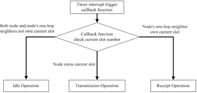
In mode selection phase, mote will wake up in the beginning of each time slot period. In this moment, mote will check some conditions and enter one of the following operations.
z Transmission operation: Mote owns current time slot, it means the mote has the possibility to transmit packets.
z Receipt operation: One of mote’s one hop neighbor nodes owns current time slot, it means the mote has the possibility to receive packet.
z Idle operation: None of above conditions then mote enters power saving mode.
Figure 4-7. Mode selection mechanism
We will explain how to implement TDMA time slot. Each mote manipulates its hardware timer counter and the corresponding interrupt will be triggered when the timer counter is overflow. Timer interrupt handler will trigger the prepared callback function. With above relations, timer interrupt will cut time axis into several time slices. Motes will do mode selection in the interrupt handler function.
Figure 4-8. Time slot and interrupt
In MICAz, ATmega128L [16] provides four hardware timers. Timer0 is used by system timer and Timer1 is used by Chipcon CC2420 [17] radio stack. Timer3 is a 16 bit timer, it will be better than 8 bit Timer2 in time resolution.
procedures must be done. We list the main procedures as below. Step 1: Disable Timer3 output compare match interrupt.
Step 2: Select timer to Clear Timer on Compare match (CTC) mode. Step 3: Select clock prescaler value.
Step 4: Select output compare register.
Step 5: Assign default values for output compare register and Timer3 counter register. Step 6: Prepare interrupt handler function.
Step 7: Enable Timer3 output compare match interrupt.
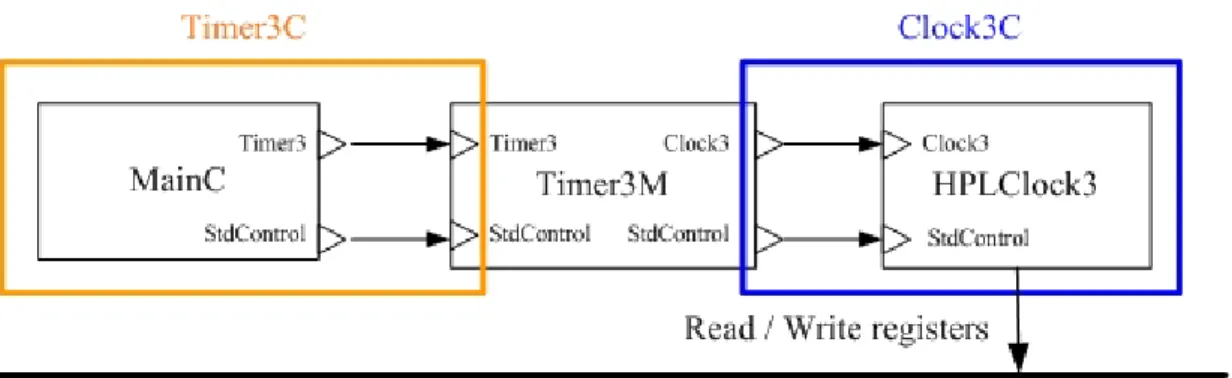
The relations between application layer program and Timer3 components are shown in Figure 4-9.
z Timer3M and HPLClock3 are components for implementation. z Configuration Timer3C wired components MainC and Timer3M. z Configuration Clock3C wired components Timer3M and HPLClock3.
z In HPLClock3, it will handle the timer and interrupt ISR by accessing the register value in ATmega128.
Both of transmission operation and receipt operations will do packets communication. There are something should be noticed as below.
z Specifying the message data to send.
z Specifying destination node to receive the message.
z Determining when the memory associated with the outgoing message can be reused. z Buffering the incoming message.
Figure 4-9. Set hardware timer in ATmega128 4.4.1 Transmission Operation
4.4.1.1 Overview
When one mote in transmission operation, it owns current time slot and it can send packets to other motes. Each mote maintains one application layer TX buffer and the data payload are stored in EEPROM.
In transmission operation, data will be retrieved from EEPROM and put it into TX buffer. Mote will read data from TX buffer and construct packet payload. Then the packet data will into Chipcon CC2420 TXFIFO through system function call. When the packet has sent done, system will signal callback function. In the callback function, we will check TX buffer and current time slot. Briefly, mote will try to transmit packets as possible as it can until TX buffer is empty or current time slot is not owned by node. 4.4.1.2 Implementation detail
In TinyOS, radio packet communication follows Active Message (AM) model, AM data structure is shown in Figure 4-10. It contains destination address, message type (AM handler ID), length, payload, etc. Each packet on the network with an AM handler ID. When a node receiving the message, system will check packet hander ID and the associated received event will be triggered. With this mechanism, we can simplify the complex transmission and receipt procedures and the source code architecture will be more clarified.
AM.h:
typedef struct TOS_Msg { uint8_t length; uint8_t fcfhi; uint8_t fcflo; uint8_t dsn; uint16_t destpan; uint16_t addr; uint8_t type; uint8_t group; uint8_t data[TOSH_DATA_LENGTH]; uint8_t strength; uint8_t lqi; bool crc; uint8_t ack; } TOS_Msg;
Figure. 4-10 AM message packet format.
When one node wants to communicate with other nodes by radio packet, its application program will wire to module GenericComm. In this module, it will provide many low level interfaces such as SendMsg and ReceiveMsg. When application program have prepared the data payload already, it will call the related commands in interface SendMsg and data payload will put into Chipcon CC2420 TXFIFO buffer. Then packet will be sent through radio interface.
For the purpose to retrieve data from EEPROM, application layer program need to wire component Logger and call related commands in interface LoggerRead to read data from EEPROM. The detail information for packet transmission is shown in Figure.4-11.
Figure 4-11. Flow chart for transmission operation. 4.4.2 Basic Receipt Operation
4.4.2.1 Overview
In basic receipt operation, node’s radio interface is still in active mode and the node is ready to receive packets from its one-hop neighbors. When mote receiving radio packets, it will store the packets into EEPROM and the data will be retrieve when mote in transmission operation.
4.4.2.2 Implement
As transmission operation, application layer program will wire component Logger for EEPROM access. Application also calls related commands in interface LoggerWrite and write data into EEPROM by SPI bus. One thing should be noticed, EEPROM will
be read and written in 16-byte blocks and both are split-phase operations.
Reference to Figure 4.2, both transmission and receipt operations use all the components in “Transmit and Receive components” and LoggerM component in “Power Management components”.
4.4.3. Idle Operation
In WSN, power saving [15] is an important topic because battery life is limited. Our target is to minimum mote power consumption. When one mote is neither in transmission nor receipt operations, it means there is no packets communication in this time slot. So we disable radio interface and trigger processor into power saving mode to reduce power consumption.
4.4.3.1. Overview
Micaz MPR2400 consists of two main chips, ATMEL ATmega128 [16] and Chipcon CC2420. For ATmega128, there are five types of clock shown in Figure 4-12 and the different power saving modes is shown in Table 4-2.
In processor idle mode, we also turn off CC2420 radio interface because there is no need for packet communication. At this moment, ATmega128 clock clkI/O is still
working and Timer/Counter overflow will trigger interrupt then wakes up processor. We use Timer3 to do the overflow and trigger operation. When the mote is awakened, it will check whether the mote into transmission or receipt mode then turn on CC2420 radio interface again.
Mode Active Clock Wake up source
Idle
clkIO , clkADC
clkASY
z The same items as ADC Noise Reduction.
z Timer / Counters overflow.
z USART transmit complete interrupt.
ADC Noise Reduction clkADC, clkASY
z The same items as Power down. z Timer/Counter0 Interrupt.
z ADC Conversion Complete interrupt z SPM/EEPROM ready interrupt.
Extended Standby
Oscillator, clkASY
z The same as Power save.
Standby oscillator z The same as Power down.
Power save clkASY
z The same items as Power down. z Timer/Counter 0 (asynchronously).
Power down None
z External Reset. z Watchdog Reset.
z Two-wire Serial Interface address. Table 4-2. Sleep mode for ATmega128 [16].
4.4.3.2 Implementation detail
In TinyOS, power management functions are implemented in component HPLPowerManagement which provides interface PowerManagement. In this interface, it access MCU control register in ATmega128 and make Micaz into different power saving modes. Upper application can wire this interface and use the provided commands to get processor current state and manipulate it into different state in Table 4-2.
We can reduce power consumption in Chipcon CC2420 by disable radio interface when the processor into sleep mode. Component CC2420ControlM provides interface SplitControl and CC2420Control which control CC2420 radio interface voltage regulator and oscillator. In interface CC2420Control, we can enable and disable voltage
regulator by commands VREFOn() and VREFOff(). Some commands are declared to enable and disable oscillator by OscillatorOn() and OscillatorOff(). Upper application wired to interface SplitControl and call provided commands to control radio interface.
Interface CC2420Control access Chipcon CC2420’s registers through interface HPLCC2420 and HPLCC2420Interrupt. Module PowerControlTDMA works as the middleware between upper application program and CC2420Control and the relations are shown in Figure 4-13.
Reference to Figure 4.2, idle operation uses HPLPowerManagement and CC2420ControlM components in “Power Management components” for different power consumption.
Chapter 5
Experiment
In this chapter, we will show the experiment results for the independent components such as time synchronization, slot assignment and power consumption.
5.1. Time Synchronization Algorithm
In order to measure the accuracy of time synchronization, we set up the test environment with four sensor nodes. Each mote connects to a mote interface board and interface board also connects to personal computer through serial port. Test environment is shown in Figure 5-1.
The source mote will broadcast information packets and all of its one-hop neighbor motes will receive these packets then record timestamp. We summary the test steps as below.
z All motes execute time synchronization algorithm (section 4.2) first. z Mote W will broadcast one hundred packets per hour.
z Motes X, Y, Z receive above broadcast packets from mote W and record current system time. System will do the comparison for the difference of packet’s timestamp between motes X, Y, Z.
For the purpose to test the stability of time synchronization algorithm, we continue this experiment until four hours. The testing results show that most of the timestamp difference between motes X, Y, Z within 2 ticks (17.36 us). After four hours pasting, timestamp difference is still stable as the beginning of this experiment.
At 0 hr, average error is 2.15 ticks (18.622 us) and result is shown in Figure 5-2 (a). At 1 hr, average error is 2.09 ticks (18.141 us) and result is shown in Figure 5-2 (b). At 2 hr, average error is 2.14 ticks (18.53 us) and result is shown Figure 5-2 (c). At 3 hr, average error is 2.46 ticks (21.35 us) and result is shown Figure 5-2 (d). At 4 hr, average error is 1.97 ticks (17.099 us) and result is shown Figure 5-2 (e). Between 0hr ~ 4 hr, average error is shown in Figure 5-2 (f).
(a) (b) (c)
(d) (e) (f)
Figure 5-2. Time synchronization test results.
Next, we will do another time synchronization experiment for two-hop neighbors. We set up the test environment with three sensor nodes. Each mote connects to a mote interface board and interface board also connects to personal computer through serial
port. The test environment is shown in Figure 5-3.
The source mote sends unicast packets to its one-hop neighbor which will send the packet to its one-hop neighbor mote again. We summary the test steps as below.
z All motes execute time synchronization algorithm (section 4.2) and calculate the propagation delay between mote X and Y, mote Y and Z.
z Mote X sends one hundred unicast packets with timestamp to mote Y per hour. z Mote Y receives above packets from mote X then re-sends these packets to mote Z.
The packet content is composed of mote X’s sending timestamp, mote Y’s receipt timestamp and mote Y’s sending timestamp.
z Mote Z will receive above packets from mote Y then records receipt timestamp. System will do the comparison for the difference of mote X’s sending timestamp and Z’s receipt timestamp. The difference value should minus propagation delay and time difference for mote Y’s receipt timestamp and sending timestamp.
Figure 5-3. Two-hop time synchronization environment.
The testing results show that most of the timestamp difference between mote X and Z within 3 ticks (26.04 us).
At 0 hr, average error is 2.60 ticks (22.568 us) and result is shown in Figure 5-4 (a). At 1 hr, average error is 2.37 ticks (20.5716 us) and result is shown in Figure 5-4 (b).
At 2 hr, average error is 2.42 ticks (21.0056 us) and result is shown in Figure 5-4 (c). At 3 hr, average error is 2.35 ticks (20.398 us) and result is shown in Figure 5-4 (d). At 4 hr, average error is 2.63 ticks (22.8284 us) and result is shown in Figure 5-4 (e). Between 0hr ~ 4 hr, average error is shown in Figure 5-4 (f).
(a) (b) (c)
(d) (e) (f)
Figure 5-4. Two-hop time synchronization test results.
5.2. Slot Assignment
In order to confirm slot assignment algorithm, we set up the test environment with four sensor nodes. Each mote connects to a mote interface board and interface board also connects to personal computer through serial port. Test environment is shown in Figure 5-5. We summary the test steps as below.
z Install firmware in mote W, X, Y, Z with different node id. z Run slot assignment algorithm.
Figure 5-5. Slot assignment environment.
In slot assignment algorithm, each node will select its slot number which is different with its one-hop and two-hop neighbors. For slot number sequence, mode with larger id will select slot number first. The test result is shown in Table 5-1.
Node W X Y Z ID 4 3 2 1
Slot number 1 2 3 1
ID 1 3 4 2
Slot number 3 2 1 3
Table 5-1. Motes slot number list.
5.3. Current Consumption
In this experiment, we switch mote ATmega128 into different power saving mode and measure the current consumption. We will disable radio interface when the mote is not in packet transmission and packet receipt mode.
We set up the test environment with one mote, power supply and current meter. Test environment is shown in Figure 5-6 and test steps as below.
z Install firmware in the mote then switch the mote into different power saving mode every ten seconds.
z Power supply connects to mote for power providing.
Figure 5-6. Current consumption test environment The current consumption in different power save mode is shown in Table 5-2.
Mode Current consumption
Active mode 8.34 mA
Active mode with packet transmission 23.51 mA
Active mode with packet receipt 23.80 mA
Idle 3.6 mA
ADC Noise Reduction 1.28 mA
Power down 17 uA
Power save 33 uA
Standby 170 uA
Extend standby 182 uA
Table 5-2. Current consumption in different mode
This experiment result shows that mote current consumption in idle mode is about 15% in packet transmission or packet receipt mode. In WSN, it is necessary to extend device working time. So we make mote into idle mode with radio interface disabled when there is no need to handle radio packets.
Assumption two AAA batteries contain 2000 mAHr then the mote can work for 3.5 days in packet transmission or packet receipt mode. Under the same scenario, mote can work for 23.1 day in idle mode.
Chapter 6
Conclusions and Future Works
In this thesis, we implement the TDMA prototype in TinyOS with hardware platform Micaz. It includes some essential elements such as time synchronization and slot assignment. We create TDMA modules as new component and other components can use it through the exported interfaces and commands. Because upper layer program will focus on the interfaces and commands name so it is simple to insert new time synchronization or slot assignment algorithm into TDMA modules. Another, we try not to do many modifications in TinyOS low level components for compatibility reason.
In the process of code implementation, it is important to understand TinyOS working flow, packet transmission, packet receipt and hardware interrupt handing. Review the experiment result, it shows stability in time synchronization which is important in TDMA model. For power consumption, we just make mote into idle mode. But the current consumption in idle mode is still too much when comparing with other power saving modes. In future work, we can do more efforts in current consumption. Another, we can implement some enhanced mechanisms for system robustness when the system motes are broken or battery resource exhausted.
References:
[1] C.-Y. Chong and S.P. Kumar, “Sensor Networks: Evolution, Opportunities, and Challenges,” in Proceedings of the IEEE, Vol. 91, No. 8, pp. 1247-1256, August 2003.
[2] H.Yang and B.Sikdar, “A Protocol for Tracking Mobile Targets using Sensor Networks” in Proceedings of the First IEEE International Workshop on Sensor Network Protocols and Applications (SNPA 2003), pp.71-81, Alaska, USA, May 2003.
[3] A. Mainwarning, D. Culler, J. Polastre, R. Szewczyk, J. Anderson, “Wireless Sensor Network for Habitat Monitoring”, Proceedings of the first ACM International Workshop on Wireless Sensor Networks and Application, pp.88-97, September 2002. [4] TinyOS, “http://www.tinyos.net/”
[5] J. Polastre, J. Hill, and D. Culler. “Verstile Low Power Media Access for Wireless Sensor Networks”. Proc. 2nd ACM Conf. Embedded Networked Sensor System (SenSys 2004).
[6] IEEE 802.11, “http://www.ieee802.org/11/index.shtml”.
[7] J. Elson, L. Girod, and D. Estrin, “Fine-Grained Time Synchronization Using Reference Broadcasts,” in Proceedings of the 5th Symposium on Operating
Systems Design and Implementation, pp. 147-163, December 2002.
[8] S. Ganeriwal, R. Kumar, M. B. Srivastava, “Timing-sync protocol for sensor
networks”, ACM Conference on Embedded Networked Sensor Systems, Nov 2003. [9] M. L. Sichitiu, and C. Veerarittiphan, “Simple, accurate time synchronization for
wireless. sensor networks”, IEEE WCNC, p.1266-73, Mar 2003. [10] M. Maróti, B. Kusy, G. Simon, and Á. Lédeczi, “The Flooding Time
Synchronization Protocol,” in Proceedings of the 2nd International Conference on Embedded Networked Sensor Systems, pp. 39-49, November 2004.
[11] Roman Lim, “Wireless Fire Sensor Network Demonstrator”, Master Thesis, Oct. 2006.
[12] J.M. Injong Rhee, Ajit Warrier, and L. Xu, “DRAND: Distributed randomized TDMA scheduling for wireless ad-hoc networks”, Proc. 7th ACM Symp. Mobile Ad Hoc Networking and Computing (MobiHoc'06), May 2006.
[13] Chih-Yu Lin, “Exploiting Spatial Correlation on the Link Layer for Event-driven Sensor Networks”.
[14] "MPR-MIB Users Manual", Crossbow, June 2007.
[15] Roman Amstutz, “Wake-up Time Estimation for a Wireless MAC Protocol”, Master Thesis, Aug 2007.
[16] ATMEL ATmega128(L) DataSheet, ATMEL Incorporated, 2006.
[17] Chipcon CC2420 DataSheet “2.4 GHz IEEE 802.15.4 / ZigBee-ready RF Transceiver”, Texas Instrument, Mar 2007.
[18] Philip Levis. “TinyOS Programming”, June 2006.
[19] “nesC 1.1 Language Reference Manual”, David Gay, Philip Levis, David Culler, Eric Brewer. 2003.
[20] IEEE 802.15 TG4, http://www.ieee802.org/15/pub/TG4.html.
[21] Barbara Hohlt and Eric Brewer. “Network Power Scheduling for TinyOS Applications”, IEEE International Conference on Distributed Computing in Sensor Systems, June 2006.