Growth and characteristics of carbon nanotubes
on carbon cloth as electrodes
Chien-Chung Chen*, Chia Fu Chen, Cheng-Hang Hsu, I-Hsuan Li
Department of Materials Science and Engineering, Nation Chiao Tung University, Hsinchu, TaiwanAvailable online 29 January 2005
Abstract
Multi-wall carbon nanotubes (MWCNT) were fabricated directly on the carbon cloth utilizing bias-assisted microwave plasma enhanced chemical vapor deposition system. The deposition of catalysts for carbon nanotubes growth was carried out by e-beam evaporation technologies. Scanning electron microscopy and transmission electron microscopy were used for characterizing the morphologies and structures of carbon nanotubes. The depositions of platinum particles on carbon nanotubes were achieved by electroless plating and sputtering. High resolution transmission electron microscopy showed that the diameters of nanotubes and platinum particles are about 20 nm and 2–5 nm, respectively. BET measurement indicated higher surface area of carbon nanotubes than carbon cloth. The electrochemical properties of carbon nanotubes electrode have been investigated by cyclic votammetry. These carbons nanotubes are very suitable for the electrodes and catalyst support of proton exchange membrane fuel cells (PEMFC).
D 2005 Elsevier B.V. All rights reserved.
Keywords: Carbon nanotubes; Sputtering; Electroless plating; Microwave plasma enhanced chemical vapor deposition
1. Introduction
Proton exchange membrane fuel cell (PEMFC) could become a mainstream of power source due to its low pollution, high efficiency and quietness. In order that PEMFC becomes a general power source, a number of obstacles must be overcome. The most serious problem is the low electrocatalytic activity of platinum catalysts of PEMFC. It is believed that the utility of platinum is a main limitation for the development of PEMFC [1]. Focus was put on finding a high surface area and good electronic property catalytic support to improve the utilization efficiency of Pt catalyst. Thus, cost reduction can be done by reducing the amount of Pt catalyst in the membrane electrode assemblies. Recently, lots of researchers have taken notice of new platinum supports for PEMFC, such as single-wall carbon nanohorn[2], carbon nanofibers[9], and carbon nanotubes
[3–8] in order to improve the electrocatalytic activity and
reduce the utility of platinum catalyst. Among them, carbon nanotubes are very attractive because of their high aspect ratio, good electronic conductivity, and high surface area. However, the conventional process for fabricating carbon nanotubes based electrode was using carbon nanotubes powers mixed with solvent and inking on the carbon cloth
[3,10]. This brings impurities into the electrode and degrades the electrochemical performance. Directly growing carbon nanotubes on the carbon cloth and depositing Pt particle on carbon nanotubes subsequently is necessary for the applica-tion of PEMFC.
In this study, multi-wall carbon nanotubes were fabri-cated directly on the carbon cloth utilizing bias-assisted MWCVD. The deposition of Pt catalyst with several nanometers on those nanomaterials was achieved by both electroless plating and sputtering methods.
2. Experiment
Multi-wall carbon nanotubes were fabricated directly on carbon cloth by bias-assisted microwave plasma enhanced
0925-9635/$ - see front matterD 2005 Elsevier B.V. All rights reserved. doi:10.1016/j.diamond.2004.12.038
* Corresponding author. Tel.: +886 3 5712121x55346; fax: +886 3 5724727.
E-mail address: [email protected] (C.-C. Chen).
Diamond & Related Materials 14 (2005) 770 – 773
chemical vapor deposition. Iron was first deposited on the carbon cloth (E-tech.) with area of 1 cm2 by e-beam evaporation. It was mainly used as the catalyst for synthesiz-ing carbon nanotubes. The reactive gas species were methane and hydrogen with a ratio of 1/4. The microwave power and the working pressure were set at 300 W and 10 torr, respectively. The additive bias was adjusted from 0 V to 200 V. An optical pyrometer was used to monitor the substrate temperature which was about 600 8C. For comparison, the deposition of platinum was carried out by means of electroless plating and sputtering techniques. The solvents of electroless plating included glycol, PVP 4000, PtCl6, and RuCl6. The concentration of the chemical solution
was 0.01 M. Moreover, the sputtering current was 10 mA and the sputtering time was 30 s. The characteristics of morphologies were achieved by means of scanning electron microscopy (Hitachi S4700I and JEOL 2500) after deposi-tion. A high resolution transmission electron microscope (Philips Tecnai-20) was used to investigate the micro-structure of carbon based nano-materials and the size of platinum particle. Structural characteristics were accom-plished by Raman spectroscopy. The surface area measure-ment was relied on the Brunauer Emmett Teller method (BET). The analysis of electrochemical properties of carbon nanotubes electrode has been done by cyclic votammetry. A platinum wire served as the counter electrode, and a saturated calomel electrode (SCE) was used as the reference electrode. The carbon nanotubes were measured in 1 M H2SO4solution
with a scanning rate of 10 mV.
3. Results and discussion
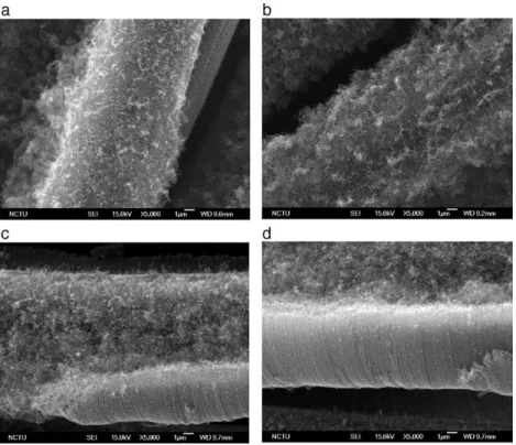
Fig. 1 shows that the carbon nanotubes were directly grown on carbon cloth by MWCVD under different additive bias. Fig. 1(a) was the image of carbon nanotubes grown without applying bias.Fig. 1(b), (c), and (d) were images of carbon nanotubes grown on carbon cloth with applying negative bias of 100 V, 150 V, and 200 V, respectively. It was easy to find that the length of CNTs was enlarged with the increasing negative bias voltage. It has been reported generally that applying negative bias could enhance the nucleation density of diamond [11–13]. This might enhance the growth rate of carbon nanotubes resulting in the elongation of the tube’s length. However, the distance between carbon nanotubes under 200 V is very small. It is difficult to deposit noble catalysts onto the surface of carbon nanotubes uniformly. On the contrary, carbon nanotubes grown without applied bias showed poor growth rate. Therefore, we choose the condition of applied 100 V as the optimal bias voltage. Raman spectroscopy was used for structural characterization. There are two distinct peaks which can be observed from the Raman spectrum. Raman spectrum of carbon nanotube shows strong peaks at 1591 cm 1(G line), which is high frequency E2g first-order mode
and 1348 cm 1 (roughly corresponding to the D-line associated with disorder-allowed zone-edge modes of graphite). The ratio of D-line to G-line (ID/IG) was 1.3.
This revealed that carbon nanotubes are characteristic of graphite. The nano-structure of the carbon nanotube grown
Fig. 1. SEM images of different negative bias for synthesizing carbon nanotubes on carbon cloth: (a) 0 V, (b) 100 V, (c) 150 V, and (d) 200 V. C.-C. Chen et al. / Diamond & Related Materials 14 (2005) 770–773 771
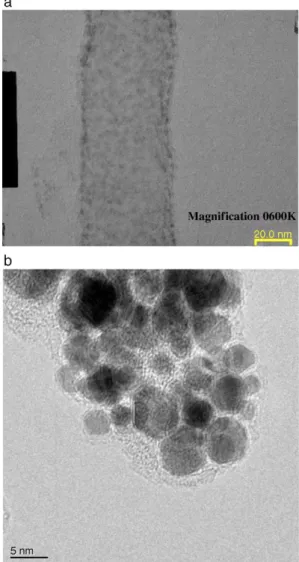
under 100 V was shown in Fig. 2. The outer and inner diameter of carbon nanotubes are about 20 nm and 10 nm, respectively. It was found that the amount of amorphous carbon around the outer shell of nanotube is very small, which was identical with the result of Raman spectrum (ID/
IG=1.3). This implied that the crystallinity of these carbon
nanotubes is good. The surface area was measured by the Brunauer Emmett Teller method. Carbon nanotubes exhibited higher surface area (90.31 m2/g) than carbon cloth alone (15.02 m2/g) from BET measurement. The enhancement of surface area by using carbon nanotubes as the electrode of PEMFC could clearly be found. Cyclic voltammetry was used to investigate the electrochemical properties of both carbon cloth and CNT/carbon cloth electrodes. The results of CV test of carbon cloth electrode and carbon nanotubes based electrode were shown inFig. 3. From the figure, we can observe that the current density of redox peaks of CNT/carbon cloth electrode (curve II) is much larger than carbon cloth (curve I). This means that the electrochemical activity of carbon nanotubes is higher than
the original carbon cloth. Therefore, the electron is easy to transport from nanotubes to the carbon cloth. This also reveals that the carbon nanotubes are suitable for the electrodes and catalyst support. The depositions of platinum particles on carbon nanotubes were achieved by electroless plating and sputtering. The sputtering is a convenient way to deposit noble metallic catalysts. It has advantages of highly uniform particle distribution and simple fabricating process. The particle size is controllable by means of controlling the sputtering time and current. However, it is quite difficult to deposit alloys via the sputtering method, such as the Pt–Ru alloy. On the other hand, electroless plating could synthesize binary catalysts and control nano-morphology easy. But, the polymer in the reaction system is hard to remove. TEM images of Pt deposited on the carbon nanotubes by different deposition methods, electroless plating and sputtering, are shown inFig. 4(a) and (b). The particle size is ~2 nm for the sputtering method and 2–5 nm for the electroless plating process. Thereby, we could observe that the uniformity of Pt
Fig. 2. TEM images of carbon nanotubes growth with applied 100 V.
I II I II 0.003 0.002 0.001 0.000 -0.001 -0.002 -0.003 -0.4 -0.2 0.0 0.2 0.4 0.6 0.8 1.0 1.2 1.4 Potential / V vs. RHE
Current density (A/cm
2)
plain carbon cloth CNT on carbon cloth
Fig. 3. Cyclic voltammograms of (I) carbon cloth electrode and (II) CNTs/ carbon cloth electrode at 10 mV/s in 1 M H2SO4aqueous solution.
Fig. 4. TEM images of different Pt deposition methods: (a) sputtering and (b) electroless plating. The particle size is ~2 nm for the sputtering method and 2–5 nm for the electroless plating process.
C.-C. Chen et al. / Diamond & Related Materials 14 (2005) 770–773 772
for the sputtering method is better than the electroless plating method.
4. Conclusion
Multi-wall carbon nanotubes (MWCNT) were fabricated directly on the carbon cloth utilizing bias-assisted micro-wave plasma enhanced chemical vapor deposition system. Furthermore, BET measurement revealed an extraordinary high surface area of carbon nanotubes based electrode. Additionally, the current density of redox peaks of CNT/ carbon cloth electrode from CV test is much larger than the carbon cloth electrode. From the observation of TEM images, the sizes of platinum particles deposited by sputtering and electroless plating process are ~2 nm and 2–5 nm, respectively. This not only simplifies the fabricat-ing process of membrane electrode assembly (MEA), but also increases the surface area of catalyst support.
Acknowledgments
The authors would like to acknowledge financial support of this work by the National Science Council of the Republic of China under contract number NSC 92-2216-E-009-028.
References
[1] S. Srinivasan, O.A. Velev, A. Parthasarathy, D.J. Manko, A.J. Appleby, J. Power Sources 36 (1991) 299.
[2] T. Yoshitake, Y. Shimakawa, S. Kuroshima, H. Kimura, T. Ichihashi, Y. Kubo, D. Kasuya, K. Takahashi, F. Kokai, M. Yudasaka, S. Iijima, Physica B 323 (2002) 124.
[3] W. Li, C. Liang, J. Qiu, W. Zhou, H. Han, Z. Wei, G. Sun, Q. Xin, Carbon 40 (2002) 787.
[4] D.B. Buchholz, S.P. Doherty, R.P.H. Chang, Carbon 41 (2003) 1625. [5] B. Rajesh, V. Karthik, S. Karthikeyan, K. Ravindranthan Thampi,
J.M. Bonard, B. Viswanathan, Fuel 81 (2002) 2177.
[6] H. Tang, J.H. Chen, Z.P. Huang, D.Z. Wang, Z.F. Ren, L.H. Nie, Y.F. Kuang, S.Z. Yao, Carbon 42 (2004) 191.
[7] H. Hou, Darrell H. Reneker, Adv. Mater. 16 (1) (2004) 69. [8] C. Wang, M. Waje, X. Wang, J.M. Tang, Robert C. Haddon, Y. Yan,
Nano Lett. 4 (2) (2004) 345.
[9] C.A. Bessel, K. Lauberns, N.M. Rodriguez, R. Terry, K. Baker, J. Phys. Chem., B 105 (6) (2001) 1115.
[10] W.Z. Li, C.H. Liang, W.J. Zhou, J.S. Qiu, Z.H. Zhou, G.Q. Sun, J.Q. Xin, J. Phys. Chem., B 107 (2003) 6292.
[11] S. Yugo, T. Kanai, T. Kimura, T. Muto, Appl. Phys. Lett. 58 (1991) 1036.
[12] J.T. Huang, W.Y. Yeh, J. Hwang, H. Chang, Thin Solid Films 315 (1998) 35.
[13] R. Sto¨ckel, K. Janischowsky, S. Rohmfeld, J. Ristein, M. Hundhau-sen, L. Ley, Diamond Relat. Mater. 5 (1996) 321.