Room temperature terahertz phase shifter based on magnetically controlled
birefringence in liquid crystals
Chao-Yuan Chen, Tsong-Ru Tsai, Ci-Ling Pan, and Ru-Pin Pan
Citation: Applied Physics Letters 83, 4497 (2003); doi: 10.1063/1.1631064
View online: http://dx.doi.org/10.1063/1.1631064
View Table of Contents: http://scitation.aip.org/content/aip/journal/apl/83/22?ver=pdfcov Published by the AIP Publishing
Articles you may be interested in
Liquid crystal phase shifters with a twist
Appl. Phys. Lett. 103, 063508 (2013); 10.1063/1.4818466 Self-polarizing terahertz liquid crystal phase shifter
AIP Advances 1, 032133 (2011); 10.1063/1.3626560
Magnetic control of negative permeability metamaterials based on liquid crystals Appl. Phys. Lett. 92, 193104 (2008); 10.1063/1.2926678
Temperature-dependent optical constants and birefringence of nematic liquid crystal 5CB in the terahertz frequency range
J. Appl. Phys. 103, 093523 (2008); 10.1063/1.2913347 Liquid-crystal-based terahertz tunable Lyot filter
Appl. Phys. Lett. 88, 101107 (2006); 10.1063/1.2181271
This article is copyrighted as indicated in the article. Reuse of AIP content is subject to the terms at: http://scitation.aip.org/termsconditions. Downloaded to IP: 140.113.38.11 On: Thu, 01 May 2014 05:17:01
Room temperature terahertz phase shifter based on magnetically
controlled birefringence in liquid crystals
Chao-Yuan Chen, Tsong-Ru Tsai, Ci-Ling Pan, and Ru-Pin Pana)
Institute of Electro-Optical Engineering and Department of Electrophysics, National Chiao Tung University, 1001 Ta Hsueh Road, Hsinchu, Taiwan 300, Republic of China
共Received 30 June 2003; accepted 8 October 2003兲
We present the use of magnetically controlled birefringence in a nematic liquid crystal cell for phase shifting of electromagnetic waves in the range of terahertz frequencies. This device can be operated at room temperature. A maximum phase shift of 141° has been demonstrated at 1.025 THz and the results are in good agreement with theoretical predictions. © 2003 American Institute of Physics. 关DOI: 10.1063/1.1631064兴
In the past decade, submillimeter wave or terahertz 共THz兲 technology1 has undergone remarkable growth with
intense interests for their applications in time-domain far-infrared spectroscopy,2,3imaging,4ranging,5and biomedical applications.6 These applications require a variety of active and passive THz optical elements such as polarizers, attenu-ators, switches, modulattenu-ators, and phase shifters, which are rarely explored up to now. Perforated flat plates that acting as dichroic filters or frequency selective surfaces in the THz range were reported by Winnewisser et al.,7 however, they were not tunable. Among active devices that permit control-ling the amplitude and phase of THz beams, there exist de-vices based on the optically excited carriers in semiconduc-tors, of which the THz transmission properties are strongly affected by illumination8,9 or carrier injection.10,11 These quantum-well-based THz tunable phase shifters,10–12 how-ever, operated at temperatures far below room temperature.
The birefringence of liquid crystals共LCs兲 is well known and extensively utilized in optical systems for control and manipulation of visible, infrared and millimeter wave beams. Indeed, several groups have employed liquid crystals suc-cessfully for phase shifting of microwave and millimeter wave signals previously.13,14 We have recently determined the complex index of refraction of a nematic LC 4
⬘
-n-pentyl-4-cyanobiphenyl 共5CB兲 at room temperature by
THz time-domain spectroscopy 共THz-TDS兲.15,16 Signifi-cantly, we show that nematic 5CB exhibits relatively large birefringence共⬃0.2兲 and small extinction coefficient 共⬍0.1兲 at frequencies around 1 THz. This indicates that 5CB in the nematic phase is potentially useful for device applications such as phase shifting in the THz frequency range. An elec-trically controlled room temperature THz phase shifter with 5CB has also been demonstrated by the authors.17 A maxi-mum phase shift of 4.07° was achieved with a driving volt-age of 177 V at 1.06 THz when the interaction length was 38.6 m. A relatively long distance共⬎2 mm兲 between the electrodes was required to avoid blocking the THz beam. The thickness of the 5CB layer required to achieve a 2 phase shift at 1 THz would be very thick共⬎3 mm兲. This also presents a problem, as alignment of the LC becomes difficult with such thick cells.
In this letter, we demonstrate a room temperature THz phase shifter based on magnetically controlled birefringence in LCs. The magnetic field is used to effectively align and change the orientation of LC molecules and hence the effec-tive index of refraction for THz waves.
A schmetic of the THz phase shifter is shown in Fig. 1. The LC phase shifter device consists of a homeotropic LC cell and a rotary magnet. The rotation axis is perpendicular to both of the polarization and the propagation directions of the THz wave. We define the magnetic inclination angle,, as the angle between the magnetic field direction and the propagation direction. The effective refractive index of LC for THz waves changes with the molecular orientation,18 which is controlled by the angle. The phase shift,␦共兲, due to magnetically controlled birefringence is given by
␦共兲⫽
冕
0 L2f
c ⌬neff共,z兲dz, 共1兲
where L is the thickness of LC layer, ⌬neff is the effective birefringence, f is the frequency of the THz waves, and c is the speed of light.
If the magnetic field is large enough, we can assume that the LC molecules are reoriented parallel to the magnetic field direction, the phase shift can then be rewritten as
␦共兲⫽2L f c •⌬neff共兲 ⫽2L f c
冋冉
cos2共兲 no2 ⫹ sin2共兲 ne2冊
1/2 ⫺no册
, 共2兲where noand neare the ordinary and extraordinary refractive indices of the LC.
The LC cells have 5CB 共Merck兲 sandwiched between fused silica plates with an area of 1 cm by 1 cm. The inner surfaces of the plates are coated with dimethyloctadecyl- 共3-trimethoxysilyl兲-propylammonium-chloride 共DMOAP兲 to align the LC molecules perpendicular to the surfaces of the quartz plate.19 To shift the THz wave phases, a Nd–Fe–B sintered magnet on a rotation stage is employed. The mag-netic field at the center of the LC cell is 5100 G. The maxi-mum possible magnetic inclination angle is 55°. Beyond that, the magnet in the present setup would block the THz a兲Electronic mail: [email protected]
APPLIED PHYSICS LETTERS VOLUME 83, NUMBER 22 1 DECEMBER 2003
4497
0003-6951/2003/83(22)/4497/3/$20.00 © 2003 American Institute of Physics
This article is copyrighted as indicated in the article. Reuse of AIP content is subject to the terms at: http://scitation.aip.org/termsconditions. Downloaded to IP: 140.113.38.11 On: Thu, 01 May 2014 05:17:01
beam. Two LC cells, with nominal thicknesses of 1 and 1.5 mm, repectively, have been used in this work. The actual thicknesses measured are 0.95 and 1.32 mm, respectively.
The device is characterized by THz-TDS. The experi-mental setup has been described previously.15 Briefly, the optical beam from a femtosecond mode-locked Ti:sapphire laser illuminates a GaAs photoconductive antenna to gener-ate the broad band THz signal, which is collimgener-ated and trans-mitted through the LC phase shifter. The transtrans-mitted THz signal is then detected by a probe beam from the same laser, using electro-optic sensing.20The measurements are done at room temperature共25 °C兲.
The temporal waveforms of the THz beam passing through the 1-mm-thick LC phase shifter at various magnetic inclination angles are illustrated in Fig. 2. The spectral width and center frequency of the incident THz pulse are 0.35 and 0.25 THz, respectively. The total scan range for the time delay was 9.58 ps, although only the data from 3 to 7 ps are shown. The transmitted THz waves for ⬎0° show obvious time delay to the wave for⫽0°. The spectral amplitude and phase of the transmitted THz wave were deduced by fast Fourier transform 共FFT兲 algorithms.
If the magnetic field is parallel to the surface, the thresh-old field18 required to reorient the LC molecules in our LC cell is 97 G, which is much lower than the field employed in this work 共5100 G兲. This means that Eq. 共2兲 is a reasonable assumption and can be used to predict the phase shifts. Al-though a field of 10 times of the threshold is usually large enough to have most of the molecules orient along the field, the much larger field used in our work is to make the LC
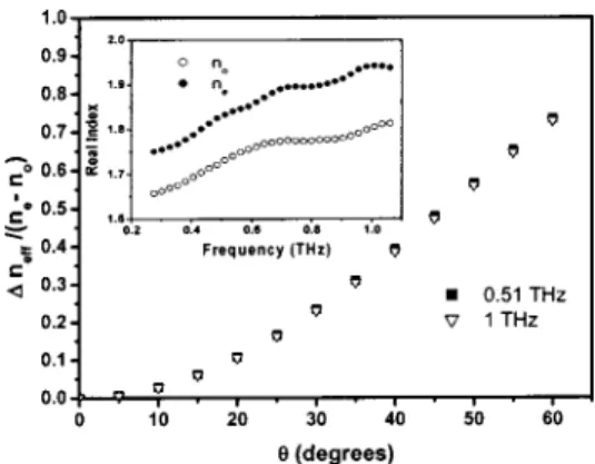
orientation stable in cells as thick as 1.5 mm. Using Eq.共2兲 and the previously measured ordinary and extraordinary in-dices of refraction of 5CB in the THz range15 共see inset of Fig. 3兲, the normalized magnetic-field-induced birefringence, ⌬neff/(ne⫺no), vsat two frequencies is plotted in Fig. 3. At
⫽60°, as high as 75% of the maximum possible birefrien-gence is realized. The phase shift due to the LC phase shifter at various frequencies are deduced from the data in Fig. 2 by FFT algorithms and plotted as a function of the magnetic inclination angle in Fig. 4. We have also calculated and plot-ted the theoretically predicplot-ted phase shifts in Fig. 4 as the solid curves. They show good agreements with the measured data. According to Eq.共1兲, the phase shift is proportional to the product of the effective index change ⌬neff and
fre-quency of the electromagnetic wave. The THz wave is thus expected to experience a larger phase shift at the higher fre-quencies in the measured THz range. This is also confirmed in Fig. 4. The data for the 1.5-mm-thick cell at 1.025 THz are also show in Fig. 4. Maximum phase shifts of 108° and 141° have been obtained at 1.025 THz by using these two LC cells, respectively.
With the LC cells with different thickness, our results show that the dependence of the phase shift on the thickness of LC layer is also consistent with the theory. The thickness of the LC layer required to achieve a 2phase shift at 1 THz is thus about 3.18 mm with the same setup used in this work. Alternatively, newly developed liquid crystal material with high birefringence can be explored for this application.
FIG. 1. Schematic diagram of a THz phase shifter using a LC cell.
FIG. 2. Measured THz waveforms transmitted through a 1-mm-thick 5CB LC cell at various magnetic inclination angles.
FIG. 3. Magnetic field induced refractive index change vsat 0.51 and 1 THz. The inset shows ordinary and extraordinary refractive indices of 5CB at 25 °C.
FIG. 4. Phase shift of the THz waves passing through the 1- and 1.5-mm LC cells vs the angle at various frequencies. The solid curves are from the theoretical predictions.
4498 Appl. Phys. Lett., Vol. 83, No. 22, 1 December 2003 Chenet al.
This article is copyrighted as indicated in the article. Reuse of AIP content is subject to the terms at: http://scitation.aip.org/termsconditions. Downloaded to IP: 140.113.38.11 On: Thu, 01 May 2014 05:17:01
In the above experiments, we also find that the trans-mited THz field increases with the magnetic inclination angle when the angle is less than 40°. This can be explained simply by considering the Fresnel equations.21The ordinary and ex-traordinary refractive indices of 5CB are 1.77 and 1.90, re-spectively, at 0.8 THz. With the increasing , the effective refractive index of LC will increase from 1.77 to 1.90共Ref. 15兲 and become closer to the refractive index of quartz sub-strate共1.95兲. The transmitted field will then increase accord-ing to Fresnel equations. The THz field decreases for⬎40° due to partial blocking of the THz wave by the magnet.
In summary, we have demonstrated a room temperature liquid crystal THz phase shifter. The phase shift is achieved by magnetically controlling of the effective refractive index of LC layer. The magnetic field also helps to align the LC for a cell as thick as 1.5 mm. Measured results are in good agreements with theoretical predictions. For the 1.5-mm-thick cell and the magnetic field inclined at 55°, the maxi-mum phase shift realized is 141° at 1.025 THz. In principle, the phase shift can be increased by employing a LC cell with larger optical thickness and/or larger magnetic inclination angle. To achieve a 2phase shift at 1 THz, we can increase the cell thickness to 3.18 mm with the same experimental setup used in this work. Alternatively, this can be realized with a 1.5-mm-thick LC cell with ⌬n⬃0.4.
This work was supported in part by the National Science Council of R.O.C. under Grant Nos. NSC 89-2218-E-009-061, 90-2112-M-009-051, and -053 and the Pursuit of Aca-demic Excellence Program of the Ministry of Education, R.O.C.
1P. H. Siegel, IEEE Trans. Microwave Theory Tech. 50, 910共2002兲. 2M. V. Exter, C. Fattinger, and D. Grischkowsky, Opt. Lett. 14, 1128
共1989兲.
3
D. Grischkowsky, S. R. Keiding, M. V. Exter, and C. Fattinger, J. Opt. Soc. Am. B 7, 2006共1990兲.
4B. B. Hu and M. C. Nuss, Opt. Lett. 20, 1716共1995兲.
5R. A. Cheville and D. Grischkowsky, Appl. Phys. Lett. 67, 1960共1995兲. 6
A. J. Fitzgerald, E. Berry, N. N. Zinovev, G. C. Walker, M. A. Smith, and J. M. Chamberlain, Phys. Med. Biol. 47, R67共2002兲.
7C. Winnewisser, F. T. Lewen, M. Schall, M. Walther, and H. Helm, IEEE
Trans. Microwave Theory Tech. 48, 744共2000兲.
8
F. A. Hegmann, J. B. Williams, B. Cole, and M. S. Sherwin, Appl. Phys. Lett. 76, 262共2000兲.
9A. Chelnokov, S. Roeson, J.-M. Lourtioz, L. Duvillaret, and J.-L. Coutaz,
Electron. Lett. 34, 1965共1998兲.
10I. H. Libon, S. Baumga¨rtner, M. Hempel, N. E. Hecker, J. Feldmann, M.
Koch, and P. Dawson, Appl. Phys. Lett. 76, 2821共2000兲.
11T. Kleine Ostmann, M. Koch, and P. Dawson, Microwave Opt. Technol.
Lett. 35, 343共2002兲.
12R. Kersting, G. Strasser, and K. Unterrainer, Electron. Lett. 36, 1156
共2000兲.
13K. C. Lim, J. D. Margerum, and A. M. Lackner, Appl. Phys. Lett. 62, 1065
共1993兲.
14D. Dolfi, M. Labeyrie, P. Joffre, and J. P. Huignard, Electron. Lett. 29, 926
共1993兲.
15T.-R. Tsai, C.-Y. Chen, C.-L. Pan, R.-P. Pan, and X.-C. Zhang, Appl. Opt.
42, 2372共2003兲.
16R.-P. Pan, T.-R. Tsai, C.-Y. Chen, C.-H. Wang, and C.-L. Pan, Mol. Cryst.
Liq. Cryst.共to be published兲.
17T.-R. Tsai, C.-Y. Chen, R.-P. Pan, C.-L. Pan, and X.-C. Zhang, IEEE
Microwave Wireless Comp. Lett.共to be published兲.
18P. G. de Gennes and J. Prost, The Physics of Liquid Crystals, 2nd ed.
共Oxford University Press, New York, 1983兲.
19F. J. Kahn, Appl. Phys. Lett. 22, 386共1973兲. 20
Z. Jiang, M. Li, and X.-C. Zhang, Appl. Phys. Lett. 76, 3221共2000兲.
21
E. Hecht, Optic, 3rd ed.共Addison Wesley–Longman, New York, 1998兲. 4499
Appl. Phys. Lett., Vol. 83, No. 22, 1 December 2003 Chenet al.
This article is copyrighted as indicated in the article. Reuse of AIP content is subject to the terms at: http://scitation.aip.org/termsconditions. Downloaded to IP: 140.113.38.11 On: Thu, 01 May 2014 05:17:01