行政院國家科學委員會專題研究計畫 成果報告
應用逆運算法估算熱鍛成形之模具表面溫度與接觸介面熱
傳導係數
研究成果報告(精簡版)
計 畫 類 別 : 個別型 計 畫 編 號 : NSC 97-2221-E-151-044- 執 行 期 間 : 97 年 08 月 01 日至 98 年 10 月 31 日 執 行 單 位 : 國立高雄應用科技大學模具工程系 計 畫 主 持 人 : 楊慶煜 計畫參與人員: 碩士班研究生-兼任助理人員:張彥暉 碩士班研究生-兼任助理人員:莊景富 博士班研究生-兼任助理人員:蕭美枝 報 告 附 件 : 出席國際會議研究心得報告及發表論文 處 理 方 式 : 本計畫涉及專利或其他智慧財產權,2 年後可公開查詢中 華 民 國 98 年 12 月 03 日
行政院國家科學委員會補助專題研究計畫
█ 成 果 報 告
□期中進度報告
應用逆運算法估算熱鍛成形之模具表面溫度與接觸介面熱傳導係數
之理論發展與實驗驗證
計畫類別:█ 個別型計畫
□ 整合型計畫
計畫編號:NSC
97 –2221 –E –151 - 044
執行期間:
97
年
8
月
1
日至
98
年
7
月
31
日
計畫主持人:楊慶煜
共同主持人:
計畫參與人員: 博士班研究生---兼任助理
蕭美枝
碩士班研究生---兼任助理
張彥暉
碩士班研究生---兼任助理
莊景富
成果報告類型(依經費核定清單規定繳交):█精簡報告
□完整報告
本成果報告包括以下應繳交之附件:
□赴國外出差或研習心得報告一份
□赴大陸地區出差或研習心得報告一份
█出席國際學術會議心得報告及發表之論文各一份
□國際合作研究計畫國外研究報告書一份
處理方式:除產學合作研究計畫、提升產業技術及人才培育研究計畫、列
管計畫及下列情形者外,得立即公開查詢
□涉及專利或其他智慧財產權,□一年█二年後可公開查詢
執行單位:
中
華
民
國
98
年
12
月
3
日
行政院國家科學委員會專題研究計畫成果報告
應用逆運算法估算熱鍛成形之模具表面溫度與接觸介面熱傳導係數
之理論發展與實驗驗證
計畫編號: NSC 97-2221-E-151 -044 執行期限:97 年8 月1 日至98 年10 月31 日 主持人: 楊慶煜 國立高雄應用科技大學模具系 中文摘要 鍛壓加工利用鍛壓機械的模具對坯料施 加壓力,使之產生塑性變形而獲得所需形狀和 尺寸的製件的成形加工方法。在熱鍛加工中能 改善金屬的塑性,使之不易開裂,減小金屬的 變形抗力,降低所需鍛壓機械的噸位並有利於 提高工件的內在品質。為使一次加熱完成儘量 多的鍛壓工作量,熱鍛的開始鍛溫度與最終鍛 溫度間的溫度區間應盡可能大。但溫度過高會 引起金屬晶粒生長過大而形成過熱現象,會降 低鍛壓件品質且溫度接近金屬熔點時會發生 晶格間低熔點物質熔化和晶格間氧化,形成過 燒,造成晶格碎裂。因此熱鍛時工件與模具溫 度為影響鍛件品質與加工難易之重要因素,若 能掌握其熱行為狀態,不但可維持熱鍛工件的 品質,且可使模具的壽命延長,同時也可瞭解 熱鍛加工作業過程的各項力學行為如變形、摩 擦等等。有關熱鍛加工溫度探討,在過去已引 起學者之重視與探討。其中又以如何求得鍛件 與模具間之熱傳係數為大家重視之焦點。此加 工行為在高溫、高壓與高速之狀態,造成實驗 上之困難度。在過去大多以改善熱電偶耐溫 性、以經驗值判斷或猜測熱傳係數值代入分析 比較求得粗略之估算值。因此本計畫擬發展一 精確、穩定與快速的熱鍛逆熱傳介面溫度與熱 傳導係數估算方法,以及開發一可行之實驗方 法,為本計畫預計達成之目標。本計畫擬以一 年時間進行熱鍛成形之模具表面溫度與接觸 介面熱傳導係數估算的理論架構與實驗驗 證。研究重點擬結合數值運算之循序方法於每 一時間區間求解模具界面溫度。研究中所用之 方法可避免以非線性最小均方根法架構估算問 題,避免增加問題的非線性。求解步驟中以混 合有限元素與有限差分法,循序解出待估測之 物理量,再予以穩定化。除了上述之優點外, 本方法能將未知條件假設可以不假設任何的形 式直接由計算機算出對應數值。這對於處理較 複雜形式的未知條件,或是未知條件的形式難 以預測時,均可準確的描述其結果。本研究的 目的是藉由模具溫度量測估算模具與工件介面 上之溫度以及估算接觸介面熱傳導係數。為了 能控制各個儀器的運作與量測,將以自行撰寫 控制程式,透過直接解的溫度分佈,估算熱鍛 成形熱傳導問題,並驗證理論結果。 關鍵詞:熱鍛成形,熱傳係數,數值循序法 AbstractThe issues of inverse manufacturing problems have been discussed such as the casting problem, the quenching problem, the grinding problem, the drilling problem and the milling problem. The milling process is a key component in the mold and die manufacturing. However, there is only a few metal forming problem have been discussed. The metal forming process is always following by a heat generation which affects among the lubrication conditions, the metal behavior, and
the quality of finished product. The accuracy of the determination of temperature during a metal forming process is important because it causes the different conditions of the interface lubrication and the material behavior. The various workpiece temperature across its dimension cause an inhomogeneous deformation and leads to a defect part such as a surface cracking or a harmful residual stresses. The increase of the die temperature reduces the allowable stress of die. A fast heat transfer from the billet to the die surface causes in a high thermal stresses. Therefore, the temperature distribution of the die and workpiece in the hot forging process is an important issues to investigate. Furthermore, an inverse algorithm is needed to develop to deal with the problem. The purpose of this research is to investigate the thermal behavior of a hot forging process. In this study, a sequential method is proposed to solve the hot forging problem step by step. The temperature condition and the heat transfer coefficient in the interface of the die and the workpiece are determined. The results are used to confirm the validity of the content of the research.
Key word:hot forging process,the heat transfer
coefficient,the sequential method
緣由與目的
逆 運 算 熱 傳 導 問 題 (Inverse heat conduction problem)簡稱為 IHCP,一般是應 用熱電耦或紅外線光學法量得固體內部點或 表面的溫度值,以反求邊界條件、熱傳係數、 表面熱傳量、內部熱源等。逆解熱傳導問題方 法已被廣泛的應用在許多設計與製造的問 題,尤其是當物體表面之狀態無法直接量測 時。 一般而言逆熱傳估算結果的精確度,是非 常的不穩定,即使小小的量測誤差也會造成無 法接受的估算結果。因此可採用正則化方法 (regularization method) [1]或未來時間觀念 (concept of the future time) [2]解決估算 不穩定的問題,其相關研究文獻為[3-9]。相關 的逆運算方法如疊代正規法 [5]、動態規劃法 [10]、the mollification method [11]、共軛 梯度法 [12]、基因演算法 [13]、符號循序法 [14]、數值循序法[15] 以及 Modified Newton-Raphson 法 [16]。逆運算法除上述理 論之發展外,同時亦有研究應用逆運算法於機 械加工估算熱傳問題的邊界,例如:在鑄造上 之運用[17-20]、熱處理過程邊界之估算[21]、 輥壓加工[22]、磨削加工[23]、鑽孔與銑削加 工[24-26]。 熱鍛加工(加工溫度溫度高於金屬再結晶溫 度)利用鍛壓機械的錘頭、砧塊、衝頭或通過 模具對坯料施加壓力,使之產生塑性變形而獲 得所需形狀和尺寸的製件的成形加工方法。加 工中,坯料整體發生明顯的塑性變形,有較大 量的塑性流動與通過改變各部位面積的空間位 置而成形,能改善金屬的塑性,使之不易開裂, 減小金屬的變形抗力,降低所需鍛壓機械的噸 位並有利於提高工件的內在品質。有關熱鍛加 工溫度探討,在過去已引起學者之重視與探討 [27-33]。其中又以如何求得鍛件與模具間之熱 傳係數為大家重視之焦點[28,30]。 因此本計畫擬進行熱鍛成形之模具表面溫 度與接觸介面熱傳導係數估算的理論架構與程 式推導估算。以數值運算之循序方法於每一時 間區間求解模具界面溫度分佈,以混合有限元 素與有限差分法,循序解出待估測之物理量, 估算熱鍛成形熱傳導問題,再予以穩定化,並 驗證理論結果。
問題描述 考慮熱鍛作業中,上模座、下模座與工件均為 預計量測與分析之物體。現以上/下模(die)前 視圖(2D)為例,如圖 1 與圖 2 所示。上/下模 的高度 L 為有限長,為了便於分析,作了如 下的假設: (1). 對 上 / 下 模 的 熱 物 理 性 質 如 比 熱 Cp
(Specific heat)、密度 (Density)、熱傳導係 數 k (Thermal conductivity)…等為常數。 (2). 上/下模為均質(Homogeneous)及等向性 (Isotropic)。 因上、下模具對稱,因此分析上模與工件,定 義此分析物體內部為V,因熱鍛過程中每一時 間點形狀都不同,因此須以數個時間點的穩態 狀態估算溫度、熱通量及模具與工件接觸介面 熱傳導係數。 以上模為例其熱傳導方程式如下: 2 2 2 2 Τ Τ k 0, 0 x a, 0 y l x y (1) k 為熱傳導係數 上模之邊界條件可作如下的描述: 1 Τ(x,t) T ,( x, y ) V , t0 (2) Τ k 0 ( x, y ) 1 3 6 7 10,t 0 x , (3) Τ k 0 ( x, y ) 4 5 8 9, t 0 y , (4) 1 T h ( Τ-Τ ) ( x, y ) 2 , t 0 y , (5) Τ(x,t)f ( t ), ( x, y )2 , t0 (6) Τ T( t ) at y l , t 0 y , (7) 在上述之邊界條件,除T( y,t ) 是預測之邊界 外,其餘均為已知。相同方程式亦可描述工件 之熱傳性質,再以熱平衡觀念求出接觸介面熱 傳導係數。 理論分析 計劃中,將使用線性有限元素將空間座標 離散化,並用有限差分法對時間座標離散化。 假設空間有np個離散點,當t tj時,式(1-7) 可被表為下列矩陣方程: j j [ A ]{ T }{ S } (8) [ A]是具np維的熱矩陣 {Sj}是未知熱傳導向量 {Tj} 是溫度向量 當ttj時,由(10)式可推得溫度分佈{Tj}如下: 1 j j { T }[ A] { S } (9) 在此 1 [ D ][ A] 相同的在tt ,..tm m 1,..,tm r 1 時每個時間點穩態 溫度分別可表示如下: m m { T }[ D ]{ S } ... m n m n { T }[ D ]{ S } (10) 在一單位列向量
ui 乘到(10)式之左右兩邊 B ottom die, 250oC Temperature acquisition system Thermocouples 圖 1、簡單壓縮熱鍛成形(simple upsetting hot forging)示意圖Top die, 250oC workpiece, 1200oC x y a l c b 圖 2、熱鍛成形上模示意圖 L 2 3 4 6 7 8 9 10 5 1
後,在第i 個空間mn個時間點的穩態溫度可 表示如下: m n i i j j m n { T } u [ D ]{ u } (11) 在此 m n j j m n { S }{ u } 在此
ui 是一單位列向量且在i 位置有一單位 的數值,而i 即表示量測點。 j { u } 是一單位行 向量,在 j 處有值。同時 m n j 表示在 j 處的熱 傳遞量大小。 m i i j j i j m m ,m m T u [ D ]{ u } 其中 i i j m ,m u [ D ]{ u } 將n 由 0 遞增到mn個獨立時間點可得: i i j m 1 m 1,m 1 m 1 T i i j m 2 m 2 ,m 2 m 2 T ... i i j m n m n ,m n m n T (12) 由上述推導,可得到: i i i i m ,m m 1,m 1 m n ,m n e0 (13) 在此e 的上標表示量測與估量的離散點,而e 的下標表示每一個穩態時間點。式(13)中的 i 0 e 值與量測與待估量的位置有關,而與全域的時 間座標無關。也就是說,在循序求解中 i 0 e 的值 為常數,僅需計算一次即可。 因此在m的時間點的穩態溫度式可寫成: (14) 在此
i m 1 2 k p i m i m i m i m p 1 T T T T , 1 2 k p i 0 i 0 i 0 i 0 p 1 e e e e 在此 p 為空間量測點的總數 當量測溫度Yj i (t tj 與 xxi)代入時,中 之元素可由線性最小均方根求得如下結果: T 1 T ) ( (15) 依此類推,計畫中將以上述方法(式 1-15) 分別估算出上模與工件之界面所有獨立時間點 之穩態溫度。再以qh(Tworkpiece Tmold )求出模 具與工件接觸介面熱傳導係數。 例題: (一)、模具部分: 考慮上模範圍在0 x a,0 y l 熱鍛時 模具與工件接觸介面,如圖 3 所示。 其中l=10mm,a=80mm,預熱後初塭 250o C,且 在 bc 範圍與工件接觸,在 y=10mm 平面處取 d 點,位置(39.6694214876, 10.0000000000)為量測 點,以 2 秒為一時間點,分別模擬 10 個時間點 上模穩態的溫度(計 20 秒),本報告取第 2、6、 10、14、18 秒上模穩態溫度顯示,如圖 4 所示。 x y a l c b 圖 3、熱鍛成形上模示意圖 d(二)、工件部分: 工件於熱鍛期間,坯料整體發生明顯的塑 性變形,每一個時間點溫度與形狀都不同,原 始形狀如圖 5 所示。 其中 a=40mm,b=20mm,預熱後初塭 1200o C, 且與上模在 bc 範圍與接觸,在接觸介面下方 10mm 平面處取任意 1 點,設定為量測點,以 2 圖 4、第 2、6、10、14、18 秒上模之穩態溫度 圖 5、熱鍛成形工件示意圖 x y a b
秒為一時間點,分別模擬 10 個時間點工件穩 態的溫度(計 20 秒),本報告取第 2、6、10、 14、18 秒工件穩態溫度顯示,如圖 6 所示。
以本研究所提出之逆運算法,分別估算上模 具與工件接觸介面各獨立時間點之暫態溫度、
熱通量q(heat flux),再以qh(Tworkpiece Tmold )
求出模具與工件接觸介面熱傳導係數,所得到 的上模與工件的穩態溫度與熱通量及熱傳導係 數分別如表 1~表 3 與圖 7~圖 9 所示。
3.50E+02 5.50E+02 7.50E+02 9.50E+02 1.15E+03 1 2 3 4 5 Time steps T e m p e ra tu re (o C ) 工件溫度(K) 上模溫度(K) 5.00E+02 2.50E+03 4.50E+03 6.50E+03 8.50E+03 1 2 3 4 5 Time steps H e a t fl u x (W /m ) 工件熱通量 (W/m) 上模熱通量 (W/m) h(W/m-k) 6.00 8.00 10.00 12.00 1 2 3 4 5 Time steps h (W /m -K ) h(W/m-k) N (sec) 溫度(K) 熱通量(W/m) 1(2) 3.8100784027E+02 9.7070370090E+02 2(6) 4.3957526995E+02 1.1199174827E+03 3(10) 4.7306104766E+02 1.2052300798E+03 4(14) 4.9856712598E+02 1.2702125867E+03 5(18) 5.1995284347E+02 1.3246975419E+03 N (sec) 溫度(K) 熱通量(W/m) 1(2) 1.0927293211E+03 5.5124912842E+03 2(6) 1.0440463743E+03 5.4414391302E+03 3(10) 1.0488145732E+03 8.0729343406E+03 4(14) 1.0263404631E+03 6.2950186592E+03 5(18) 9.7034744456E+02 5.6210499932E+03 N (sec) h(W/mk) 1(2) 6.3814114167E+00 2(6) 7.1492609264E+00 3(10) 1.1928201837E+01 4(14) 9.5207652965E+00 5(18) 9.5390851509E+00 表 1、第 2、6、10、14、18 秒上模之穩態溫度與熱通 表 2、第 2、6、10、14、18 秒工件之穩態溫度與熱通 表 3、第 2、6、10、14、18 秒模具與工件接觸介面之 熱傳導係數 圖 7、第 2、6、10、14、18 秒上模與工件之估算穩態溫度 圖 8、第 2、6、10、14、18 秒上模與工件之估算熱通量 圖 9、第 2、6、10、14、18 秒上模與工件之熱傳導係數
計畫結果自評 熱鍛加工若掌握熱行為狀態,不但可維持 熱鍛工件的品質,且可使模具的壽命延長,同 時也可瞭解熱鍛加工作業過程的各項力學行 為如變形、摩擦等等。 本研究所討論之逆運算方法可有效運用 於設計、製造問題,計畫中先行推導直接解問 題,再運用數值運算之循序法解決逆問題。結 果顯示研究中所用方法,可有效且精確的估算 熱鍛過程中熱傳介面溫度、熱通量與熱傳導係 數,解決熱鍛加工的種種熱行為問題。 參考文獻
1. Tikhonov, A. N. and Arsenin, V. Y.,
Solutions of Ill-posed Problems, 1st ed.,
Winston, Washington, DC, 1977.
2. Beck, J. V., Blackwell, B. and Clair, C. R. St., Inverse Heat Conduction-Ill Posed
Problem, 1st ed., Wiley, New York, 1985.
3. Morozov, V. A. and Stessin, M.,
Regularization Methods for Ill-Posed Problems, 1st ed., CRC Press, Inc., 1993.
4. Alifanov, O. M., Inverse Heat Transfer
Problems, 1st ed., Springer-Verlag, Berlin
Heidelberg, 1994.
5. Liu, J., "A Stability Analysis on Beck's procedure for Inverse Heat Conduction Problems," Journal of Computational Physics, Vol. 123, 1995, pp. 65-73.
6. Reinhardt, H. J., "A Numerical method for the Solution of the Two-Dimensional Inverse Heat Conduction Problem,"
International Journal for Numerical Methods in Engineering, Vol. 32, 1991, pp.
363-383.
7. Alifanov, O. M. and Artyukhin, E. A., "Regularized Numerical Solution of Nonlinear Inverse Heat Conduction Problem," Journal of Engineering Physics, Vol. 29, No. 1, 1975, pp. 934-938.
8 Alifanov, O. M. and Mikhailov, V. V., "Solution of the Nonlinear Inverse Thermal Conductivity Problem by the Iteration
Vol. 35, No. 6, 1978, pp. 1501-1506.
9. Beck, J. V. and Murio, D. A., "Combined Function Specification-regularization Procedure for Solution of Inverse Heat Conduction Problem," AIAA Journal, 1986, Vol. 24, pp. 180-185.
10. Busby, H. R. and Trujillo, D. M., "Numerical Solution to A Two-Dimensional Inverse Heat Conduction Problem," International Journal
for Numerical Methods in Engineering, Vol.
21, 1985, pp. 349-359.
11. Murio, D. A., The Mollification Method and
the Numerical Solution of Ill-Posed Problems , Wiley-Interscience, New York,
1993.
12. Jarny, Y., Ozisik, M. N. and Bardon, J. P., "A General Optimization Method Using Adjoint Equation for Solving Multidimensional Inverse Heat Conduction," International Journal of Heat and Mass Transfer, Vol. 34,
No. 11, 1991, pp. 2911-2919.
13. Li., H. Y. and Yang, C. Y., "A Genetic Algorithm for Inverse Radiation Problems,"
International Journal of Heat and Mass Transfer, Vol. 40, No. 7, 1997, pp. 1545-1549.
14. Yang, C. Y., “A Sequential Method to Estimate The Strength of The Heat Source Based on Symbolic Computation,"
International Journal of Heat and Mass Transfer, Vol. 41, No. 14, 1998, pp. 2245-2252.
15. Yang, C. Y., “Inverse Estimation of Mix-typed Boundary Conditions in Heat Conduction Problems," AIAA Journal of
Thermophysics and Heat Transfer, Vol. 12,
No. 4, 1998, pp. 552-561.
16.Yang,C.Y.,“Determination ofTemperature Dependent Thermophysical Properties from Temperature Responses Measured ad Medium’sBoundaries,"International Journal of Heat and Mass Transfer, Vol.43, 2000, pp.
1261-1270
17.Broucaret,S.;Michrafy,A.;Dour,G “Heat transfer and thermo-mechanical stresses in a gravity casting die: Influence of process parameters,”Journal of Materials Processing Technology Volume: 110, Issue: 2, March 19, 2001, pp. 211-217.
transfer coefficient at the metal–mould interface in the unidirectional solidification of Cu–8%Sn alloys,” International Journal of Heat and Mass Transfer Volume: 43, Issue: 14, July, 2000, pp. 2541-2552.
19. Vila Real, P.M.M.; Oliveira, C.A.M.; Barbosa, J.T., “Thermo-elasto–viscoplastic numerical model for metal casting processes,” International Journal of Mechanical Sciences Volume: 46, Issue: 2, February, 2004, pp. 245-261.
20. C. H. Huang and Y. C. Wang , "The Estimation of Solid-Liquid Moving Front Position During Metal Casting", Proceedings of NSC (EI paper), Vol. 20, No.26, pp. 194-203, 1996.
21. Huiping Li, Guoqun Zhao, Shanting Ni and Yiguo Luan, “Inverse heat conduction analysis of quenching process using finite-element and optimization method,”Finite Elements in Analysis & Design Volume: 42, Issue: 12, August, 2006, pp. 1087-1096.
22. C. H. Huang, T. M. Ju and A. A. Tseng, "The Estimation of Surface Thermal Behavior of Working Roll in Hot Rolling Process", Int, J. Heat and Mass Transfer (SCI&EI paper), Vol. 38, No. 6, pp. 1019-1031, 1995.
23.Hong,K.K.;Lo,C.Y.,“An inverseanalysis for the heat conduction during a grinding process,”Journal of Materials Processing Technology Volume: 105, Issue: 1-2, September 7, 2000, pp. 87-94.
24.Attia, M.H.; Fraser, S.; Osman, M.O.M., “On-line estimation of time-variant thermal load applied to machine tool structures using a s-domain inverse solution,”International Journal of Machine Tools and Manufacture Volume: 39, Issue: 6, June, 1999, pp. 985-1000.
25.Chung, Sung-Chong, “Temperature estimation in drilling processes by using an observer,”International Journal of Machine Tools and Manufacture Volume: 45, Issue: 15, December, 2005, pp. 1641-1651.
26. Lin, Jehnming, “Inverse estimation of the tool-work interface temperature in end milling,”International Journal of Machine Tools and Manufacture Volume: 35, Issue: 5,
May, 1995, pp. 751-760.
27. Nshama, W. and Jeswiet, J, “Evaluation of temperature and heat transfer conditions at the metal-forming interface,” AnnalsofCIRP Volume: 44, 1995, pp. 201-204.
28.Chang, C. C. and Bramley, A. N., “Determination of the heat transfer coefficient at the workpiece-die interface for theforging process,”IMechE PartB:Journal of Engineering Manufacture Volume: 216, 2002, pp. 1179-1186..
29.Li,Y.H.and Sellars,C.M.,“Comparative investigations of interfacial heat transfer behaviour during hot forging and rolling of steelwithg oxidescaleformation,”Journalof Materials Processing Technology Volume: 80-81, 1998, pp. 282-286.
30. Rosochowska, M., Balendra, R. and Chodnikiewiczm, K., “Measurement of thermal contact conductance,” Journal of Materials Processing Technology Volume: 135, 2003, pp. 204-210.
31.PolozineA.and Schaeffer,L.,“Exactand approximate methods for determining the thermalparametersoftheforging process,” Journal of Materials Processing Technology Volume: 170, 2005, pp. 611-615
32. Wilson, William R. D., Schmid, Steven R. and Liu Jiying,“Advanced simulationsfor hot forging: heat transfer model for use with thefiniteelementmethod,”Journalof Materials Processing Technology Volume: 155-156, 2004, pp. 1912-1917.
33. Kang, J. H., Lee, K. O. and Kang, S. S., “Characterization ofcooling heattransferfor various coolant conditions in warm forging process,”JournalofMaterialsProcessing Technology Volume: 184, 2007, pp. 338-344.
可供推廣之研發成果資料表
□ 可申請專利 ■ 可技術移轉 日期:98 年 12 月 3 日國科會補助計畫
計畫名稱:應用逆運算法估算熱鍛成形之模具表面溫度與接觸介面 熱傳導係數之理論發展與實驗驗證 計畫主持人:楊慶煜 計畫編號:NSC 97-2221-E-151 -044 學門領域:E72技術/創作名稱
應用逆運算法估算熱鍛成形之模具表面溫度與接觸介面熱傳導係 數之理論發展與實驗驗證發明人/創作人
楊慶煜技術說明
中文: 熱鍛時工件與模具溫度為影響鍛件品質與加工難易之重要因素,若 能掌握其熱行為狀態,不但可維持熱鍛工件的品質,且可使模具的 壽命延長,同時也可瞭解熱鍛加工作業過程的各項力學行為如變 形、摩擦等等。有關熱鍛加工溫度探討,在過去已引起學者之重視 與探討。其中又以如何求得鍛件與模具間之熱傳係數為大家重視之 焦點。此加工行為在高溫、高壓與高速之狀態,造成實驗上之困難 度。在過去大多以改善熱電偶耐溫性、以經驗值判斷或猜測熱傳係 數值代入分析比較求得粗略之估算值。因此本計畫發展一精確、穩 定與快速的熱鍛逆熱傳介面溫度與熱傳導係數估算方法,預計達成 之目標。本計畫進行熱鍛成形之模具表面溫度與接觸介面熱傳導係 數估算的理論架構與實驗驗證,結合數值運算之循序方法於每一時 間區間求解模具界面溫度。對於處理較複雜形式的未知條件,或是 未知條件的形式難以預測時,均可準確的描述其結果。本研究是藉 由模具溫度量測估算模具與工件介面上之溫度以及估算接觸介面 熱傳導係數。透過直接解的溫度分佈,估算熱鍛成形熱傳導問題, 並驗證理論結果。 (100~500 字)英文:
The issues of inverse manufacturing problems have been discussed such as the casting problem, the quenching problem, the grinding problem, the drilling problem and the milling problem. The milling process is a key component in the mold and die manufacturing. However, there is only a few metal forming problem have been discussed. The metal forming process is always following by a heat generation which affects among the lubrication conditions, the metal behavior, and the quality of finished product. The accuracy of the determination of temperature during a metal forming process is important because it causes the different conditions of the interface lubrication and the material behavior. The various workpiece temperature across its dimension cause an inhomogeneous deformation and leads to a defect part such as a surface cracking or a harmful residual stresses. The increase of the die temperature reduces the allowable stress of die. A fast heat transfer from the billet to the die surface causes in a high thermal stresses. Therefore, the temperature distribution of the die and workpiece in the hot forging process is an important issues to investigate. The purpose of this research is to investigate the thermal behavior of a hot forging process. The temperature condition and the heat transfer coefficient in the interface of the die and the workpiece are determined. The results are used to confirm the validity of the content of the research.
可利用之產業
及
可開發之產品
熱鍛加工中能改善金屬的塑性,使之不易開裂,減小金屬的變形抗 力,降低所需鍛壓機械的噸位並有利於提高工件的內在品質,且可 使模具的壽命延長,同時也可瞭解熱鍛加工作業過程的各項力學行 為如變形、摩擦等等。技術特點
藉由模具溫度量測估算模具與工件介面上之溫度以及估算接 觸介面熱傳導係數。透過模具與工件介面直接解的溫度分佈,估算 熱鍛成形熱傳導問題。推廣及運用的價值
熱鍛加工之製程技術 ※ 1.每項研發成果請填寫一式二份,一份隨成果報告送繳本會,一份送 貴單位研發成果 推廣單位(如技術移轉中心)。 ※ 2.本項研發成果若尚未申請專利,請勿揭露可申請專利之主要內容。 ※ 3.本表若不敷使用,請自行影印使用。出席國際學術會議心得報告
單 位 高雄應用科技大學
職 稱 教授
姓 名 楊慶煜
會議名稱
International Conference on Electronics Packaging (ICEP) 2009
會議時間
2009 年 4 月 14 日至 4 月 16 日
會議地點
Kyoto, Japan
論文名稱
Characterization and Properties of Nanometric-Sized SnO2/CNT
Composited Materials for Lithium-Battery Anodes
計畫編號
NSC 97-2221-E-151 -044
心得:
一、 會議經過
本次會議主要探討奈米級尺寸SnO2/CNT的複合材料在鋰電池陽極的特性,
會議於2009 年4 月14 日至16 日舉辦。共有數百餘篇論文參與此次會議。主辦單位
邀請演講者為相當具有聲望之學者。本人發表之論文於會議中以張貼形式發表,也
承蒙許多學者提問與討論,獲益匪淺。研討會論文主要內容包含十四項主題:
1. Packaging,
2. Substrate/Materials
3. Design/Evaluation/Simulation
4. Manufacturing Process
5. Interconnection
6. Optoelectronics
7. Nano technologies
8. MEMS
9. RF/RFID
10. Organic semiconductors
11. Trend/Education Aspects
12. Energy/Environmental Aspects
13. Application
14. Other subject relating to Electronics Packaging
二、 會議心得
期望來年能持續參與 ICEP 相關會議,並邀請知名學者到國內講學與研究,盼
望國內亦能有學術單位願意爭取與具有國際地位之組織合辦研討會,以增加與國外
學者交流之機會。
Characterization and Properties of Nanometric-Sized SnO
2/CNT Composited
Materials
for Lithium-Battery Anodes
Wein-Duo Yanga,*, Ching-Yu Yangb, Hsin-Yun Fanga, Mao- Sung Wua, Hui- Mei Tsaic, Ching-Yuan Hsiehc, Ching-Shieh Hsiehd
a
Department of Chemical and Materials Engineering, National Kaohsiung University of Applied Sciences, Kaohsiung, Taiwan
b
Department of Mold and Die Engineering, National Kaohsiung University of Applied Sciences, Kaohsiung, Taiwan
c
Materials & Electro-Optics Research Division Battery Section, Chung-Shan Institute of Science & Technology, Lung-Tan, Tao-Yuan, 325, Taiwan.
d
Department of Applied Chemistry, Fooyin University, Ta-Liao 831, Taiwan.
Abstract
Nanometric-sized tin oxide/carbon nanotube composite materials used for Lithium-ion battery anodes were obtained from the resins synthesized by the polymerized complex technique based on a novel sol-gel method. The precursors were characterized by XRD and SEM, and those mechanisms for the evolution of SnO2 powders in this process was
proposed and discussed in the context of the microstructure. At reaction temperature of 600 ℃ a rutile-structural SnO2
phase and the particle size of 30-40 nm was synthesized. The nanoparticles as anode materials in lithium-ion batteries exhibit high lithium storage capacities. At 700 ℃, the SnO2/CNT showed the increasing of about 250 mAh/g in specific
capacitance from that of SnO2 58.05 mAh/g to 298.66 mAh/g.
Keywords: Nanometric-sized tin oxide, Lithium-ion battery, Sol-gel, SnO2/CNT
1. Introduction
Recently, lithium ion secondary batteries have been used to as substitutes of other battery systems due to their high capacity, higher voltage and long cycle life. However, there are still so much problems left for scholars and researchers to further improve lithium ion battery technologies, such as, development of high efficient electrodes and high performance electrolyte, etc. Since Fuji reported that an amorphous tin oxide was utilized to an anode electrode [1], there have been tremendous researchers are interested in tin oxide anodes in lithium ion batteries. However, the demerit of the use of SnO2 is
demonstrating the irreversible during the charge/discharge process [2].
SnO2/carbon nanotube (CNT) composites have
stimulated great interest owing to their fantastic properties and promising applications for improving the reversible charge/discharge, therefore, the SnO2/CNT
composites have been given much attention because their performance in lithium ion batteries was enhanced via the introduction of CNTs [3,4].
A simple powder preparation method was developed by a novel sol-gel process [5], in which citric acid was used to chelate metal ions and hydropropyl cellulose (HPC) was used as solvent to obtain an intermediate of polyester-type resin. HPC greatly inhibits metal ions segregation and achieves a homogeneous precursor in the polymerization of citric acid-metal complexes [6]. These chelates undergo polyesterification to form a solid polymer resin in which the cations are uniformly dispersed. The resin is subsequently calcined at lower temperatures to yield fine oxide particulates.
In this study, nanometric-sized SnO2/CNT
composites with high surface area as anodes for lithium ion batteries were synthesized by the novel sol-gel process. Carbon nanotubes play the roles of increasing conductivity leading to less charge-transfer resistance, improved high rate capability, using as the catalyst support for nanometric-sized tin oxide particles formation, as well as increasing the stability and cycle life of anodes, to improve electrochemical performance of anodes.
2. Experimental
Nanometric-sized SnO2 powders were prepared by
the novel sol-gel technique using the following high-pure starting materials: SnCl4·5H2O as metal ion sources,
de-ionized water as solvent, citric acid (C6H8O7·H2O) as
chelating agent and hydroxypropyl cellulose (M=105) as dispersant agent. First, the sol was formed at 65 ℃ by mixing SnCl4·5H2O with citric acid, and added small
amount of hydroxypropyl cellulose in de-ionized water. Then, the sol was evaporated at 120 ℃ in dry oven until the gel was formed. Finally, Nanometric-sized SnO2
powders were obtained by calcining the dried gel precursors in air at various temperatures between 300- 800 ℃ for 4 h. The procedure was also repeated by dispersing a certain amount of carbon nanotube in the solution at the beginning to produce SnO2/CNT
composite precursors. Those too were heated for 4 h in air at 300-800 oC, respectively.
Physical properties of dried citric acid-cellulose-metal ion gels were investigated by X-ray powder diffraction (XRD) (RIGAKU, Rint-2000) and
scanning electron microscopy (SEM) (JEOL-5610). Furthermore, the characteristics of calcined SnO2 and
SnO2/CNT materials were analyzed: the crystalline phase
was identified by an X-ray diffractometer (XRD), the surface area was determined by a BET analyzer (Micromeritics, ASAP 2101), and the surface structure and particle morphology were examined by a scanning electron microscope (SEM).
The electrochemical properties of SnO2/CNT were
measured with three-electrode cells. The anode was prepared by dipping the as-prepared sol containing SnO2/CNT in ethanol solvent. The resulting slurry was
pressed on nickel foil which was then dried at 200 ℃ in an oven. The counter electrode and the reference electrode were Pt wire and saturated Ag/AgCl electrode, respectively. The electrolyte was 1 M LiClO4, of which
the solution pH was corrected to 8-10 by LiOH addition. Cyclic voltammetry was performed at room temperature with a scan rate of 1mV/s. The charge/discharge measurement was performed on a LAND CT2001A testing system.
3. Results and discussion
Electron micrographs of the products from the novel sol-gel process after calcination at various temperatures for 4 h are shown in Fig. 1. Except the sample calcined at 300 oC Fig. 1(a) showed an irregularly shape owing to the uncompleted combustion, all samples of SnO2 were
morphologically alike, and showed the particles in spherical shape and with a few noticeable irregularity. Chemical analysis reported virtually no trace of carbon and hydrogen for samples heated above 500 oC, the composition of the as-prepared powders is basically pure SnO2.
Fig. 1 SEM the products from the novel sol-gel process after calcination at various temperatures for 4 h. (a) SnO2
obtained at 300 oC, (b) SnO2 obtained at 500 oC, (c)
SnO2 obtained at 600 oC , (d) SnO2 obtained at 700 oC ,
and (e) SnO2/CNT composite obtained at 700 oC .
The free volume in these materials is likely to increase with the heat-treatment temperature, when residual carbon and hydrogen were burned off progressively from the precursor. The more open structure serves to buffer against the volume change in lithium insertion and extraction reactions, and also provides a facilitated pathway for the transport of lithium ions [7].
The high-temperature samples were more cycleable and had higher specific capacities. The particle sizes of SnO2 calcined at 500 oC, 600 oC , 700 oC , were 20-30
nm, 30-40 nm, and 40-60 nm, respectively. As in the composite, it was found that carbon nanotubes disperse well and separate with each other clearly. Meanwhile, spherical tin oxide nanoparticles were found to cover carbon nanotubes pretty uniformly (Fig. 1(e)).
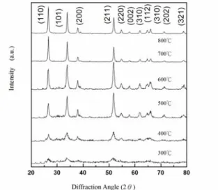
To confirm the existence of crystalline SnO2 samples
after calcination, X-ray powder diffraction was performed. The XRD spectra of as-prepared SnO2
calcined at various temperatures are shown in Fig. 2. All peaks in the scan range 20–80o can be indexed to the three major peaks of SnO2, namely, the (110), (101), and
(211) diffractions. The peak intensities increase slightly with increase in heat-treatment temperature. This demonstrates the stability of the smaller grains.
Fig. 2 The XRD spectra of as-prepared SnO2 calcined at
various temperatures.
Fig. 3 shows the discharge curves of the nanometric-sized SnO2 electrode obtained from the
various calcined temperatures. In the discharge curve of the SnO2 prepared at 700 oC, the nanometric-sized SnO2
electrode has a surprisingly high discharge capacity of 761 mAh g-1 due to the unique structure of SnO2, which
is larger than that of other SnO2 nanostructures [8]. The
discharge capacities of the electrode obtained at 400 oC, 500 oC and 600 oC are 57, 98, 206 mAh g-1, respectively.
It has been reported that Li–Sn alloys only exist
(a) (b)
(c)
.
(d)
below 0.8 V, and hence Sn is likely to be reformed in the discharge cycles around 0.9 V [9]. At discharge potentials higher than 1.3 V, some Li2O decomposition
may take place and result in deterioration of cycle-life. Given these possibilities, the discharge limit was capped at 1 V in all the experiments reported here.
Fig. 3 The 1st discharge of anode SnO2 anode
obtained at various temperatures.
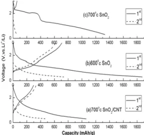
Fig. 4 shows the first two-cycle’s charge/discharge curves of the samples prepared from various conditions. The plateau at approximately 0.75 V in the first discharge curve for the SnO2/CNT electrode may be
related to the formation of a passivation film or solid electrolyte interphase on the carbon surface. There are long, discernible potential plateaus from 1.2 to 0.7 V in the first discharge curve for the SnO2/CNT or SnO2
electrode. At 700 ℃ , the SnO2/CNT showed the
increasing of about 250 mAh/g in specific capacitance from that of SnO2 58.05 mAh/g to 298.66 mAh/g.
Fig. 4 The first two-cycle’s charge/discharge curves of the samples prepared from various conditions.
We introduce a concept of relative irreversible capacity- Coulomb efficiency, which is defined as the discharge capacity (Cdhg) divided by discharge capacity
at the same cycle, i.e. Cdhg /Cchg ; and the capacity
retention is defined as the discharge of n cycle divided the first run discharge, Cdhg (n) /Cdhg (1), to represent the
decay of the electrode. Fig. 5 shows the Coulomb efficiency and capacity retention of SnO2/CNT
composite electrode obtained at 700 oC. This expresses the percent of the intercalated lithium in each cycle, which cannot be deintercalated. As it is shown, the relative irreversible capacity of the SnO2/CNT is in good
quality. This result indicates that the coating of SnO2
may hinder/reduce the solid electrolyte interphase formation on the surface of CNT for the SnO2/CNT
electrode; hence it can reduce greatly the irreversible capacity, and improve the charge capacity at the same time.
Fig. 5 shows the Coulomb efficiency and capacity retention of SnO2/CNT composite electrode obtained at
700 oC.
SnO2/CNT shows a much higher charge capacity and
a better durability against decay than unsupported SnO2.
Thus, the composite of SnO2/CNT demonstrates a great
benefit on the excellent electrochemical performance. We attribute this result to the good dispersion of SnO2 on
CNT, as we believe the well-dispersed SnO2 has a highly
utilized-coefficient, and the thin layer produced or small particle size is beneficial in releasing the stress caused by the drastic volume variation during the lithium intercalation/deintercalation process [10].
4. Conclusions
Nanometric-sized SnO2 powders are obtained from a
novel sol-gel method followed by heat treatment above 500 oC. The materials are resistant to tin atom agglomeration and exhibited good cycle-life in rechargeable Li batteries. SnO2/CNT composites were
prepared, and the morphology, structure, and electrochemical properties were investigated by SEM, XRD, and charge/discharge test. The resulting SnO2/CNT has shown an enhanced electrochemical
performance compared with the SnO2. The
electrochemical behavior of the composite may be controlled by both the SnO2 and CNT. At 700 ℃, the
SnO2/CNT which showed the increasing of about 250
mAh/g in specific capacitance from that of SnO2 58.05
mAh/g to 298.66 mAh/g.
References
1. R. Zhang, J. Y. Lee, Z.L. Liu, “ Pechini process-derived tin oxide and tin oxide–graphite composites for lithium-ion batteries " , Journal of Power Sources, vol. 112, pp. 596–605, 2002.
2. J. Read, D. Foster, J. Wolfenstine, W. Behl, “SnO2-carbon composites for Lithium-ion Battery
Anodes", J. Power Sources, vol. 96, pp. 277-281, 2001.
3. J. Xie and Vijay K. Varadan, “ Synthesis and Characterization of High Surface Area Tin Oxide / Functionalized Carbon Nanotubes Composite as anode Materials", Materials Chemistry and Physics, vol. 91, pp. 274-280, 2005.
4. Z. Wang, G. Chen, D. Xia, “Coating of Multi-Walled Carbon Nanotube with SnO2 Films of Controlled
Thickness and its Application for Li-Ion Battery”, J. Power Sources, vol. 166, pp. 1419-1424, 2008.
5. H. K. Park, D. K. Kim, C. H. Kim, “Effect of solvent on titania particle formation and morphology in thermal hydrolysis of TiCl4”,J. Amer. Ceram. Soc.,
vol. 80, pp. 743-749, 1997.
6. J. D. Tsay, T. T. Fang, “Effect of molar ratio of citric acid to cations and pH value on the formation and thermal-decomposition behavior of barium titanium citrate”, J. Am. Ceram. Soc., vol. 826, pp. 1409-1415, 1999.
7. J. Xie, V. K. Varadan, “ Synthesis and characterization of high surface area tin oxide/functionalized carbon nanotubes composite as anode materials", Materials Chemistry and Physics, vol. 91, pp. 274–280, 2005.
8. N. Du, H. Zhang, B. Chen, X. Ma, X. Huang, J. Tu, D. Yang, “Synthesis of polycrystalline SnO2 nanotubes
on carbon nanotube template for anode material of lithium-ion battery”, Materials Research Bulletin, vol. 44, pp. 211–215, 2009.
9. K.M. Abraham, “Recent developments in secondary lithium battery technology”, J. Power Sources, vol. 14, pp. 179-191, 1985.
10. M. H. Chen, Z.C. Huang,G. M. Zhu, J. K. You, Z. G. Lin, “Synthesis and Characterization of SnO-Carbon Nanoture Composite as Anode Material for Lithium-Ion Batteries”, Materials Research Bulletin, vol . 38, pp. 813-836, 2003.