國立臺灣大學工學院化學工程學研究所 博士論文
Department of Chemical Engineering College of Engineering
National Taiwan University Doctoral Dissertation
以高壓原位製備法合成光電有機高分子/無機氧化物之 奈米混成系統及其混摻型態、光電性質與太陽能元件之
研究
In Situ Template Synthesis of Conjugated Polymer/Inorganic Oxide Nanohybrid System at Elevated Pressures: Study on Hybrid Morphology, Optoelectronic Properties and Application in Solar Cells
江奇儒 Chi-Ju Chiang
指導教授:戴子安 博士 Advisor:Chi-An Dai, Ph.D.
中華民國 105 年 7 月
July, 2016
致謝
在台大博士班7年的修業生涯終要在此告一個段落,對我來說,完成這份博士論文 的過程是充滿著說不盡的人生奇妙旅程,其中包含了太多的酸甜與苦辣,這些生 活中的點點滴滴,雖然沒有記錄在這本論文中,但其所帶給我的成長,並不亞於 在學業中所獲得的科學知識和專業教養,有些時候,我都覺得這會不會是為什麼 博士學位要稱作Ph.D. (Doctor of Philosophy)的原因!?光陰飛逝,這精華的7年光陰 就這樣順利地走過了,感覺像是做了一場夢,非常地真實又覺得虛幻,這一切我 要感謝許許多多的人對我的提攜、愛護和幫助。
首先,我要特別真誠地感謝我的指導教授--戴子安老師,這麼多年來,您對我或 是對於每一個學生,總是能夠不厭其煩的有耐心的去引導學生並啟發學生關於在 科學研究上的各種專業知識和技能;生活方面,您也是總是非常樂於與我們分享 您的人生經驗,不論是老師過去的留學和工作經驗分享,都使我的眼界開闊了不 少。此外,老師您在待人處事上的善良、包容與正直,亦深深地影響著我,感謝 您過去對我做得不夠好的地方,給予最大的包容和鼓勵,才讓我有機會成長而變 得更好。在我即將踏入職場的此刻,我會謹記您給我的諄諄教誨,勇往開拓一篇 屬於自己的人生篇章,努力去做好自己的每個角色,盡自己所能對社會作出貢獻。
在實驗方面,我要特別感謝宜桓學長的指教,給予了我在研究課題上許多重要的 建議和幫助,而你在研究上的熱枕和堅持,亦是讓我非常佩服和欣賞的模範。我 也要感謝鈞傑學長,感謝你曾經教過我陰離子聚合技術,你在實驗時候嚴謹細心 的態度,著實讓我印象深刻。我也要謝謝有長達五年坐在我隔壁位子的同窗--楊宜 龍同學,謝謝你陪伴我經歷太多的事情,帶給我不論是在研究或是生活上,都有 著莫大的幫助和快樂。我也非常謝謝李育凭同學,感謝你這7年來不論是在任何大
當然,也非常感謝曾經一起在這個實驗室中生活過的各位學弟妹們,立恒、明豪、
品嘉、冠廷、孟弘、泓瑋、凡凱、俊安、泱卉、國璋、怡萱、柏廷、瑀岑、學昱、
柏安、雅勤…,謝謝你們在實驗室各種事務上的幫助與平時閒暇之餘的聊天和分 享,非常感謝你們,有你們這些學弟妹,讓實驗室生活增添了非常多的樂趣,這 真是段難得的美好人生經歷。
最重要的,還有我的父母親、家中長輩及教育過我的師長們,感謝您們從我還非 常小開始就非常用心地養育我、栽培我,不求回報的給予我最誠摯的愛。特別要 謝謝爸媽您們總是處處替我設想,有您們的支持,讓我得以無後顧之憂地在學校 中求學,不必擔憂經濟上的問題,在這裡真的要向您們致上最深的謝意。在未來,
我會穩健的踏穩每一個腳步,經營好人生,好讓您們感到欣慰和放心!
最後,我想將這本論文獻給我的未婚妻及正在媽媽腹中的孩子,
這本論文的完成,不是個結束,它是我們共譜未來人生的開始!
願 所有曾經幫助過我的人,祝福您們 平安 喜樂。
摘要
有機/無機混成材料因其具有低成本、柔曲性、輕穎性以及便於量化製造的優 點,因此是個極具前瞻性的研究主題。然而,要得到較好的功能特性,需仰賴較 大的電荷傳導界面及建構良好的傳輸結構來達成,而這樣的控制技術至今仍然是 一項待需克服的重要課題。在這本論文裡,我們開發了一項新穎的原位高壓水熱 法來製備共軛高分子/無機奈米粒子之混成材料,且此材料具有自組裝成奈米線結 構的特性。在第一部分的研究中,聚噻吩高分子(P3HT)和鈦前驅物先相互作用並 共組裝成奈米線之結構,再經由水熱法將鈦前驅物直接在 P3HT 之奈米線上轉化成
具結晶性之二氧化鈦(TiO2)奈米顆粒。P3HT 奈米線在此混成系統中,除了當作電
子提供者外,亦可做為一種模板來達到有效分散二氧化鈦奈米顆粒的目的。特別 的是,相較於一般高結晶性二氧化鈦的製備需經過高達 450 °C 以上的高溫鍛燒,
以此高壓水熱法(~7 bars)製備具高結晶度之銳鈦礦型 TiO2的製備溫度則可以大幅
降低至 130 °C。因此,此方法提供了一種可以經由一個步驟的過程,就製備出同
時含有高結晶度之 P3HT 和 TiO2混成奈米線。這樣的結構大幅提升了此 P3HT/TiO2
混成系統中的電子傳輸界面以有效促成激質的分離(exciton dissociation),而得以獲 得較佳的元件表現。相較於非使用此原位合成法製備之奈米混成系統的元件效率
而言(PCE: 0.03%),經由原位高壓法製備之 P3HT/TiO2混成元件則具有達 0.14%的
效率表現,表現出顯著之進步。
第二個部分中,則是以相似的原位高壓水熱法來製備製備 P3HT/ZnO 奈米粒 子之混成材料,此混成材料具有長約 500 nm 以上,寬約 24 nm 左右的奈米線結構。
P3HT 分子鏈上的硫原子可作為一種固定座,用來與鋅前驅物形成錯合物(complex),
再經由高壓水熱法(~9 bars)將鋅前驅物直接在 P3HT 之奈米線上轉化成具結晶性之 氧化鋅(ZnO)奈米顆粒。P3HT 和 ZnO 的配位鍵結力可以帶來控制分散 ZnO 奈米顆 粒的作用,以達到較佳的分散效果。經由此高壓水熱法,可在相對低溫的 150 °C
成之 ZnO 奈米顆粒則仍然幾乎是在非晶相(amorphous)的狀態。特別的是,此原位 高壓水熱法不但可以在 P3HT 奈米線上直接合成出具高結晶性的 ZnO 奈米顆粒,
亦同時可以達到提升 P3HT 結晶度的效果。藉由光學物理的分析顯示此 P3HT/ZnO 奈米混成材料的確具有較佳之 UV 吸收、良好之螢光淬熄(PL quenching)效應,以 及較短的激質生命週期。這些光電特性的提升代表著此 P3HT/ZnO 奈米線結構符 合預期地提供了大量的激質分離界面及連續的網絡來傳輸電荷。
在 第 三 個 部 分 裡 , 一 種 含 有 全 共 軛 鏈 段 之 嵌 段 共 聚 高 分 子 poly(2,5-dihexyloxy-p-phenylene)-b-poly(3-hexylthiophene) (PPP-b-P3HT) 被 用 來 取 代先前的 P3HT 當作線性模板來製備具高規整度之核/殼型奈米線混成系統。分子 鏈具雙親性(amphiphilic)的 PPP-b-P3HT 在這個系統中可作為具自組裝能力的模板 分子亦可作為有效的電子提供者。同樣的,以此高壓水熱法(~7 bars)亦成功地在相
對低溫之 130 °C 下製備出之具高結晶度之 TiO2奈米顆粒。值得注意的是,經由 X
射線光電子能譜(XPS)的證明,鈦前驅物及 TiO2奈米顆粒傾向於和 PPP 鏈段上的
氧原子作用,而不是去和 P3HT 鏈段上的硫原子作用。此合成出之 PPHT/TiO2混
成系統會自組裝成為一核/殼型奈米線結構,其線寬約 36 nm,而且絕大部分之 TiO2
奈米顆粒是存在於非晶相的 PPP 鏈段之中。同時,經由低銳角入射廣角 X 光散射 實驗(GIWAXS)確認了此原位高壓水熱法可以協同性地合成出具有高結晶度的
P3HT 奈米線以及 TiO2奈米顆粒。因此,以此方法製備出的 PPHT/TiO2混成材料
亦具有大面積的激質分離界面及連續的電荷傳輸網絡,表現出優異的螢光淬熄效 應。基於以上之研究開發,這本論文揭示了一種極具潛力的方法以利用原位方式 製備有機/無機奈米混成材料,且這樣的材料是可以由各種不同的導電共軛高分子 和無機奈米顆粒來搭配組成,可以預期此材料在未來諸多先進光電元件中相當具 有應用發展性。
關鍵字: 混成太陽能電池;聚噻吩高分子;二氧化鈦;氧化鋅奈米粒子;奈米線。
Abstract
Organic/inorganic hybrid structures are promising systems for a variety of optoelectronic applications because of their low cost, flexibility, light weight, and ease of large-scale production. However, the ability to control the morphology for obtaining large area of interfaces and continuous pathway for enhanced functional properties is still an important issue that needs to be overcome. In this work, we developed a novel in situ high pressure hydrothermal method to fabricate self-assembled π-conjugated polymer/inorganic nanoparticles hybrid nanowires. In the first part, wherein a facile one-step synthetic strategy was utilized to co-organize conducting polymer, poly(3-hexylthiophene) (P3HT), and titanium precursors into highly elongated hybrid nanowires, followed by a hydrothermal process in an autoclave to in situ transform the titanium precursors into crystalline TiO2 nanoparticles on the P3HT nanofibrils. P3HT nanofibrils were utilized as a structure-directing motif to achieve a favorable dispersion of electron acceptor (A) TiO2 nanocrystals of 10-15 nm in diameter embossed along the nanofibrils, as well as an efficient electron donor (D) for the nanohybrid. Particularly, the crystallization temperature of anatase-phase TiO2 nanoparticles with high crystallinity via the hydrothermal method was significantly reduced to 130 °C in an elevated pressure of ~7 bars as compared to the conventional calcination temperature of
synergistic one-step fabrication of both highly crystalline TiO2 nanoparticles embossed on highly crystalline long-range ordered P3HT nanofibrils. As a consequence of the structural development, this P3HT/TiO2 embossed nanohybrids could afford significant improvements in their D/A interfacial contact area for effective charge separation without the need of capping ligands typically used in ex-situ D/A blend systems, as well as efficient pathway for charge transport, leading to enhanced optoelectronic properties and device performance. The highest conversion efficiency of 0.14% was presented from the P3HT/TiO2 embossed hybrid device, which was a remarkable improvement as compared to only 0.03% from an ex-situ P3HT/TiO2 hybrid device.
In the second part, we carried out a systematic investigation using a hydrothermal process to fabricate P3HT/ZnO nanohybrids thin film comprising of ZnO nanocrystals embossed on self-assembly P3HT nanofibrils which were more than 500 nm in length along its fibril long-axis with an average fibril width of ~24 nm. The sulfur atoms at the thiophene ring of the P3HT molecules were used to act as anchoring sites with zinc oxide precursors for the formation of zinc-sulfur complexes, followed by utilizing the hydrothermal crystallization process at an elevated pressure (~9 bars) in an autoclave to grow highly crystalline ZnO nanoparticles in situ on the existing P3HT nanofibrils. The coordinate bonding between P3HT and ZnO nanoparticles carried advantages over a randomly distributed hybrid system, resulting in a better control of morphology to
achieve a favorable dispersion of nanocrystals in this hybrid system. The high pressure hydrothermal process demonstrated the ability to synthesize highly crystalline monophasic wurtzite-type ZnO nanoparticles situated on P3HT fibrils under relatively low temperatures (150 °C), while the ZnO nanoparticles in the other P3HT/ZnO hybrid sample prepared via a thermal oxidation treatment at 150 °C in ambient air remained mostly amorphous. In particular, the in situ hydrothermal process can not only be used to synthesize highly ordered ZnO nanocrystals embossed on P3HT nanowires, but also to synergistically enhance the crystallinity of P3HT nanofibrils due to the hydrothermal method at elevated pressure appears to have no adverse effect on the physical and chemical properties of P3HT. Photophysical property analysis showed that the P3HT/ZnO hybrid thin films exhibited enhanced vibronic absorption, photoluminescence quenching, and shorter exciton lifetime. The enhancement in these optoelectronic properties indicated that the ZnO embossed nanofibrillar structure was expected to provide a large area of D/A interfaces for efficient excitons dissociation as well as a continuous pathway for charge transport, thereby improving the optoelectronic properties.
In the third part, an all π-conjugated diblock copolymer poly(2,5-dihexyloxy-p-phenylene)-b-poly(3-hexylthiophene), PPP-b-P3HT was used as a linear nanotemplate for the synthesis to yield nanohybrids with highly ordered
donor/acceptor (D/A) core-shell nanowire structure that exhibit enhanced optoelectronic properties. The amphiphilic diblock copolymer of PPP-P3HT was used as both a synergistic long-range ordered structure-directing template and an efficient exciton donor for the nanohybrids. The novel in situ high-pressure hydrothermal process provided us a facilitating way to fabricate PPP-P3HT/TiO2 nanohybrids with highly crystalline TiO2 nanoparticles at a reduced temperature of 130 °C in an elevated pressure of ~7 bars. In particular, as evidenced by the XPS measurements, the titanium precursors and TiO2 nanoparticles were surrounded and interacted with the oxygen atoms on the side chains of PPP block rather than the sulfur atoms of thiophene on main chains in this diblock copolymer/TiO2 hybrid system. Therefore, the synthesized PPP-P3HT/TiO2 nanohybrids self-assembled into a 1-D D/A core-shell nanowire structure of uniform width (~36 nm), wherein the TiO2 nanoparticles were embedded in the amorphous PPP phase mostly. Meanwhile, the GIWAXS results confirmed that the novel high pressure hydrothermal treatment was an effective methodology to synergistically fabricate organic/inorganic hybrid materials with high crystallinity for both the PPP-P3HT copolymer and TiO2 nanoparticles. Thus, the resulting PPP-P3HT/TiO2 hybrid material displayed a considerably enhanced PL quench effect due to the TiO2 embossed nanofibrillar structure could provide enhanced D/A interfacial area for charge separation as well as an efficient pathway for charge transport between
the PPP-P3HT copolymer and the confining TiO2 nanoparticles in the desired domain.
Base on the promising developments, this work can pave a potential way to apply the in situ approach for fabricating organic/inorganic nanohybrid materials consisting of
conjugated polymers with different inorganic nanoparticles for future advanced applications in optoelectronic devices.
Keywords: hybrid solar cells; P3HT; TiO2; ZnO nanoparticles; nanowires.
Contents
致謝
………...…I摘要
………IIIAbstract
………...…VContents
………...………...…XFigure Caption
………...…XVTable Caption
………..…………....XXVChapter 1 Introduction
………...…... 11-1 Introduction of conjugated polymers………..…1
1-2 Configuration and synthesis of poly(alkylthiophene)……….4
1-3 Catalyst-transfer polymerization: Grignard metathesis, GRIM……….8
1-4 Self-assembly of conjugated polymer-containing block copolymers………...14
1-5 Conjugated polymer/inorganic nanoparticles hybrid system………....19
1-6 Configuration and synthesis of TiO2 nanostructures……….22
1-7 Configuration and synthesis of ZnO nanostructures……….28
References………...33
Chapter 2 In situ hydrothermal fabrication of D/A P3HT/TiO
2hybrid nanowires and its application in photovoltaic devices
………..…………362-1 Introduction………..36
2-2 Material and equipments………..41
2-3 Synthesis of P3HT homopolymer via Grignard metathesis method…………44
2-3-1 Synthesis of 2,5-dibromo-3-hexylthiophene monomer………..44
2-3-2 Polymerization of P3HT homopolymer……….45
2-4 Characteristics of P3HT homopolymer………...47
2-4-1 1H Nuclear magnetic resonance (1H NMR)………47
2-4-2 Gel permeation chromatography (GPC)……….50
2-5 In situ synthesis of P3HT/TiO2 nanohybrids with a nanowire structure……..52
2-6 Characterization methods of synthesized P3HT/TiO2 nanohybrids…….……55
2-6-1 X-ray photoelectron spectroscopy (XPS)………...55
2-6-2 Transmission electron microscopy (TEM)………56
2-6-3 Grazing incidence small-angle and wide-angle X-ray scattering (GISAXS and GIWAXS)………...56
2-6-4 Photophysical property analysis……….57
2-7 Solar cell device fabrication and characterization………...58
2-7-1 Preparation of FTO-coated glass substrates………...59
2-7-2 Synthesis and preparation of compact TiO2 (c-TiO2)……….59
2-7-3 Deposition of P3HT/TiO2 hybrid nanowires as active layer…………..60
2-7-4 Current-voltage characteristics of solar cells……….60
2-8 Results and discussion……….61
2-8-1 Study on fabrication process of P3HT/TiO2 hybrid system via the high-pressure hydrothermal treatment………61
2-8-2 Study on complex formation between P3HT and titanium nanohybrids………67
2-8-3 Morphology and self-assembly behaviors………..70
2-8-4 Molecular packing of P3HT and TiO2 in nanodomains……….76
2-8-5 Photophysical properties of P3HT/TiO2 nanohybrids………80
2-8-6 Device performance………86
2-9 Conclusions………..90
References………..92
Chapter 3 Synergistic In Situ Hybrid Synthesis of Highly Crystalline P3HT/ZnO Nanowires at Elevated Pressures
………..973-1 Introduction………...97
3-2 Material and equipments……….102
3-3 Characteristics of P3HT homopolymer………...…105
3-4 In situ synthesis of P3HT/ZnO nanohybrids with a nanowire structure…….106
3-5 Characterization methods of synthesized P3HT/ZnO nanohybrids…………110
3-5-1 X-ray photoelectron spectroscopy (XPS)………..110
3-5-2 Transmission electron microscopy (TEM)……….111
3-5-3 Grazing incidence wide-angle X-ray scattering (GIWAXS)………….111
3-5-4 Photophysical property analysis………112
3-6 Results and Discussion………113
3-6-1 Study on fabrication process of P3HT/ZnO hybrid system via the high pressure hydrothermal treatment………...113
3-6-2 Study on complex formation between P3HT and zinc nanohybrids….119 3-6-3 Morphology and self-assembly behaviors……….125
3-6-4 Molecular packing of P3HT and ZnO in nanodomains……….130
3-6-5 Photophysical properties of P3HT/ZnO nanohybrids………135
3-7 Conclusions……….142
References……….144
Chapter 4 In Situ Template Synthesis of All π-conjugated Diblock Copolymer/TiO
2Hybrid Nanowires with Enhanced Charge Transfer Performance
………...1494-1 Introduction……….149
4-2 Material and equipments……….151
4-3 Synthesis of PPP-b-P3HT diblock copolymer via Grignard metathesis method 4-3-1 Synthesis of 1,4-dibromo-2,5-dihexyloxybenzene monomer…………155
4-3-2 Polymerization of PPP-b-P3HT diblock copolymer………..156 4-4 Characteristics of the synthesis of PPP-b-P3HT diblock copolymer………..158 4-4-1 1H Nuclear magnetic resonance (1H NMR)………...158 4-4-2 Gel permeation chromatography (GPC)………161 4-5 In situ synthesis of PPP-P3HT/TiO2 nanohybrids with a nanowire structure.163 4-6 Characterization of synthesized PPP-P3HT/TiO2 nanohybrids………..166 4-7 Results and Discussion………168 4-7-1 Study on complex formation between PPP-P3HT and titanium
nanohybrids………...168 4-7-2 Morphology of PPP-P3HT/TiO2 nanohybrids with nanowire
structures………173 4-7-3 GIWAXS spectra of PPP-P3HT/TiO2 nanohybrids………...179 4-7-4 Photophysical properties of PPP-P3HT/TiO2 nanohybrids…………...188 4-8 Conclusions……….192 References……….194
APPENDIX
……….………...196Figure Caption
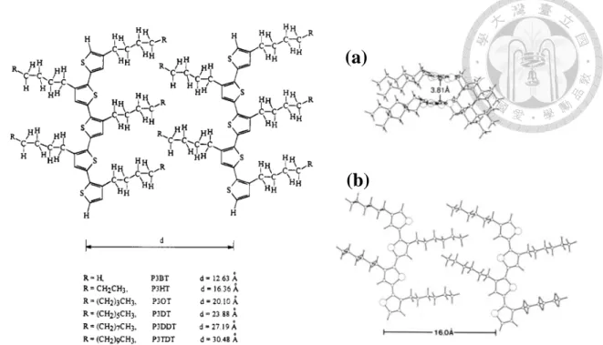
Figure 1-1 The principal conducting polymers……….2 Figure 1-2 Configurations of poly(3-alkylthiophene)………...6 Figure 1-3 NMR spectra of (a) regiorandom P3HT and (b) regioregular P3HT………...7 Figure 1-4 2-D lamellar structure with interlayer spacing of H-T P3ATs. (a)
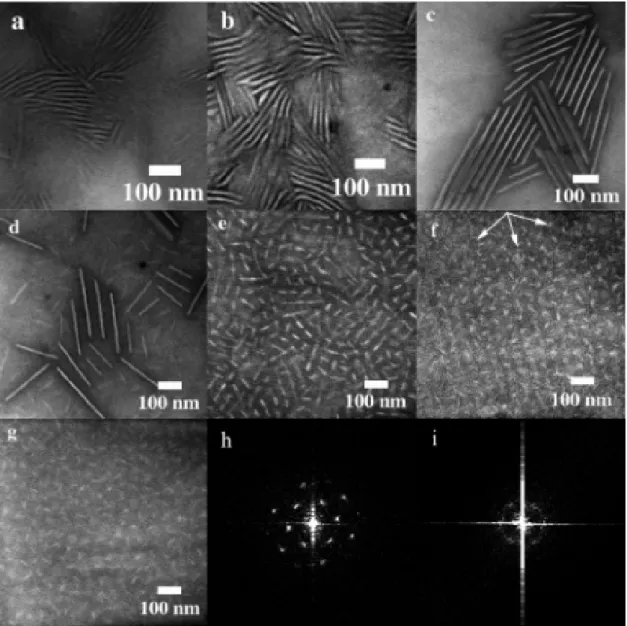
Intermolecular π stacking between thiophene rings. (b) Lamellar stacking…..8 Figure 1-5 Proposed Mechanism for the Nickel-Initiated Cross-Coupling……….11 Figure 1-6 Proposed Mechanism of Chain-Growth Polymerization………...11 Figure 1-7 The synthesized sequence of PPP-b-P3HT by Grignard metathesis………..13 Figure 1-8 TEM images and Fourier Transforms of PPV-b-PI block copolymers. (a) PPVbPI-31, (b) PPVbPI-41, (c) PPVbPI-57, (d) PPVbPI-71, (e) PPVbPI-81, (f) PPVbPI-87 and (g) PPVbPI-91. Fourier transforms of these polymers show that both have 6-fold symmetries characteristic of a hexagonal
structure. (h) PPVbPI-87 and (i) PPVbPI-91……….17 Figure 1-9 Phase behavior of PPV-b-PMMA block copolymers……….18 Figure 1-10 Nanowire morphology in PS-P3HT block copolymers solvent-cast from toluene and visualized with tapping-mode AFM. Left: height image; right:
phase image……….………..18
semiconductor nanoparticles and conducting polymer films; (b) blend of semiconductor nanorods and conducting polymer films; (c) blend of
semiconductor nano-tetrapods and conducting polymer films; (d) conducting polymer immersed in porous semiconductor nano-network; (e) blend of semiconductor nanorods arrays and conducting polymer films; and (f) blend
of semiconductor nanotube arrays and conducting polymer films…………21
Figure 1–12 The phase diagram of TiO2………..24
Figure 1–13 Two kinds of TiO2 crystal structures: (a) rutile, (b) anatase………25
Figure 1–14 The combination of chains of (a) rutile and (b) anatase………..26
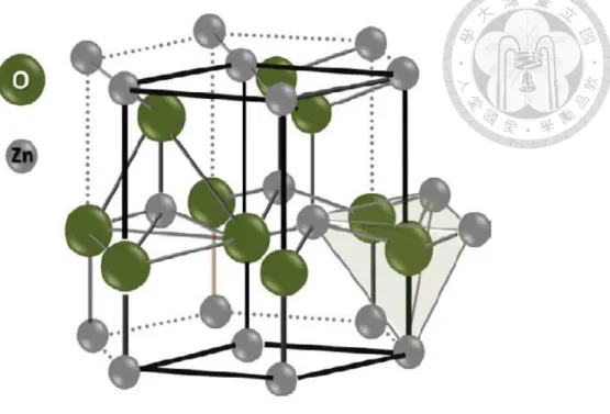
Figure 1-15 The crystal structure of a hexagonal wurtzite ZnO………..31
Figure 1-16 SEM images of the as-synthesized ZnO nanobelts, showing helical nanostructure………...31
Figure 1-17 SEM images of ZnO powder hydrothermally prepared at pH = (a) 9, (b) 10, (c) 11, and (d) 12………..32
Figure 2-1 The synthesis scheme of 2,5-dibromo-3-hexylthiophene………..46
Figure 2-2 Schematic illustrations of polymerization of P3HT homopolymer………...46
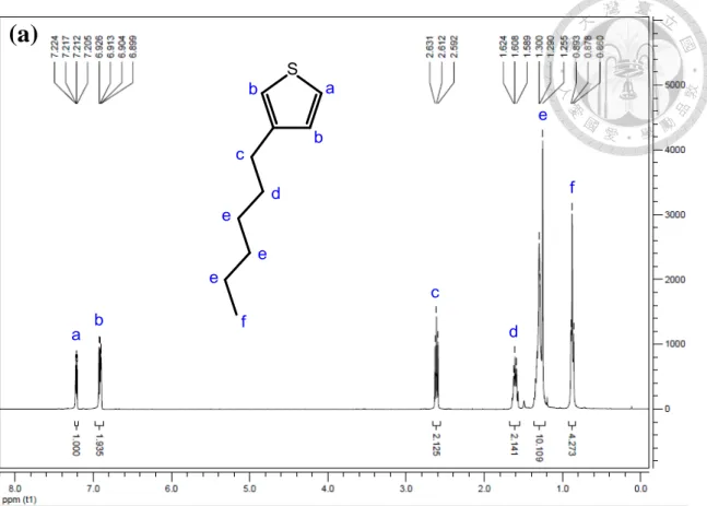
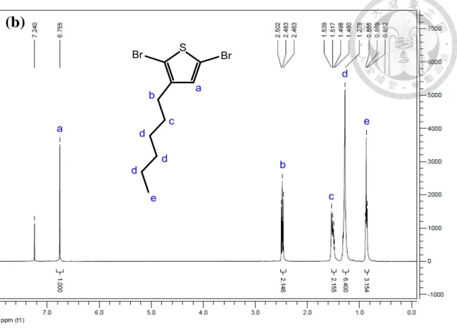
Figure 2-1 1H NMR spectra and the structural assignments of 3-hexylthiophene in CDCl3……….48 Figure 2-4 1H NMR spectra and the structural assignments of 2,5-dibromo-3-
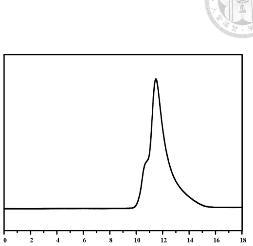
hexylthiophene in CDCl3………...49 Figure 2-5 1H NMR spectrum of P3HT homopolymer in CDCl3………...50 Figure 2-6 GPC trace of the P3HT56 homopolymer synthesized by using the Grignard metathesis method……….51 Figure 2-7 Procedure for preparation of P3HT/TiO2 hybrids with nanowire structures.54 Figure 2-8 Schematic illustration showing the architecture of a photovoltaic device….61 Figure 2-9 Reaction scheme for the formation of in situ nanohybrid containing TiO2 nanoparticles decorated P3HT nanofibrils via the high-pressure
hydrothermal crystallization process……….65 Figure 2-10 The WAXS spectra of solvent-cast P3HT/TiO2 (with a fixed TiO2 content 3HT/TiO2 = 1:1) hybrid thin film samples after various lengths of annealing time during the hydrothermal crystallization process, i.e., 2 h, 6h, and 9 h, respectively at 130 oC. The inset picture shows the XRD profiles of the corresponding P3HT/TiO2 hybrid samples magnified by 5 times………….66 Figure 2-11 The XPS spectra of S 2p orbital of pristine P3HT nanofibrils, TTIP chelated P3HTnanofibrils with a 3HT/Ti molar ratio of 1:1 and embossed P3HT/TiO2
nanohybrids fabricated via the hydrothermal crystallization
process at 130 oC for 6 h………69 Figure 2-12 TEM images of drop-cast samples of the nanofibrillar structures of (a)
pristine P3HT, (b) P3HT/TiO2 hybrid with 3HT/TiO2 = 1:0.33, (c) P3HT/TiO2 hybrid with 3HT/TiO2 = 1:1 and (d) P3HT/TiO2 hybrid with 3HT/TiO2 = 1:2. All of the above samples were prepared via the
hydrothermal crystallization process……….74 Figure 2-13 Two-dimensional GISAXS scattering patterns of thin films of (a) pristine P3HT, (b) P3HT/TiO2 hybrid with 3HT/TiO2 = 1:1, and (c) P3HT/TiO2
hybrid with 3HT/TiO2 = 1:2 samples. For the GISAXS measurements, an incident angle of 0.2° was used. To obtain statistically averaged information on the internal structure of these thin film samples, the corresponding
one-dimensional scattering spectra in the horizontal direction (d) of the above three images were taken. The arrows indicate the scattering peaks associated with the structural characteristics of these samples’ nanofibrils…75 Figure 2-14 Two-dimensional GIWAXS scattering spectra of (a) P3HT/TiO2 hybrid with 3HT/TiO2 = 1:0.33, (b) P3HT/TiO2 hybrid with 3HT/TiO2 = 1:0.66, (c) P3HT/TiO2 hybrid with 3HT/TiO2 = 1:1 and (d) P3HT/TiO2 hybrid with 3HT/TiO2 = 1:2. The corresponding one-dimensional GIWAXS profiles along qz, and qxy axis were extracted for the four samples, as shown in (e) and (f), respectively……….79 Figure 2-15 (a) UV-VIS and (b) PL spectra of pristine P3HT and the in situ grown
P3HT/TiO2 hybrid samples with different molar ratio of 3HT monomer units to TiO2 by exciting the tested samples at 550 nm………85 Figure 2-16 (a) Time-resolved photoluminescence spectra of pristine P3HT and the P3HT/TiO2 hybrid samples with different molar ratios of 3HT units to TiO2 by exciting the samples at 478 nm of monochromic light. (b) The energy-level diagram for the co-assembled P3HT/TiO2 hybrid D/A network system…….86 Figure 2-17 Current density-voltage (J-V) characteristics of the P3HT/TiO2 hybrid based photovoltaic devices under 100 mW/cm2 AM 1.5G solar irradiation...89 Figure 3-1 GPC trace of the P3HT32 homopolymer synthesized by using the Grignard metathesis method………...106 Figure 3-2 Procedure for preparation of P3HT/ZnO hybrids with nanowire
structures………109 Figure 3-3 In situ synthetic pathway for the template fabrication of nanohybrids
containing ZnOnanoparticles decorated P3HT nanofibrils via the
high-pressure hydrothermal crystallization process………..…117 Figure 3-4 The WAXS spectra of solvent-cast pristine P3HT and P3HT/zinc hybrid thin film samples (with a fixed molar ratio 3HT/Zn = 1:1). The XRD profiles in (b) and (d) are magnified by 5 times. In (a) and (b), the curves correspond to Zn(Ac)2 chelated P3HTnanofibrils, P3HT/ZnO hybrids via the hydrothermal
crystallization process (HCP) at 110 oC for 2 h, and the bottom curve
corresponds to the pristine P3HT nanofibrils for comparison. For the curves in (c) and (d), which demonstrated the synergistic effect of HCP (150 oC, 2 h) on fabricating highly crystalline P3HT/ZnO hybrid film relative to the
P3HT/ZnO hybrid sample prepared by heating the P3HT/Zn(Ac)2 sample under the ambient air condition at 150 oC..…..……….118 Figure 3-5 (a) The XPS spectra of S 2p orbital of a pristine P3HT film (bottom), Zn(Ac)2 chelated P3HT with a 3HT/Zn molar ratio of 1:1 (middle), and the embossed P3HT/ZnO nanohybrids fabricated via HCP at 150 oC for 2 h (top). (b) Schematic representation of the P3HT/Zn hybrid nanowire
structure at different stages of synthesis in the HCP process...123 Figure 3-6 The Zn 2p high resolution XPS spectra of the Zn(Ac)2 chelated P3HThybrid sample (bottom) and the P3HT/ZnO nanohybrids (top) via the HCP at 150 oC for 2 h………..………..124 Figure 3-7 TEM micrographs of (a) pristine P3HT nanofibrils and different
P3HT/Zn(Ac)2 chelate complexes with 3HT/Zn2+ molar ratios of (b) 1:0.33, (c) 1:1, and (d) 1:3, respectively. After the high pressure hydrothermal crystallization process, TEM images of the P3HT/ZnO hybrid samples were obtained with different ZnO content (3HT/ZnO) of (e) 1:0.33, (f) 1:1, and (g)
1:3. The micrograph in (h) shows the TEM image of P3HT/ZnO hybrid sample prepared by heating the P3HT/Zn(Ac)2 sample under the ambient air condition with 3HT/ZnO = 1:1. The inset pictures in (e), (f) and (g) show the TEM images of the corresponding areas magnified by 5 times………...….129 Figure 3-8 Two-dimensional GIWAXS scattering spectra of (a) P3HT/ZnO hybrid with 3HT/ZnO = 1:0.33, (b) P3HT/ZnO hybrid with 3HT/ZnO = 1:1, (c)
P3HT/ZnO hybrid with 3HT/ZnO = 1:2 and (d) P3HT/ZnO hybrid with 3HT/ZnO = 1:3………..133 Figure 3-9 XRD patterns of the P3HT/ZnO hybrid samples with different 3HT/Zn(Ac)2 molar ratios after the hydrothermal treatment………...134 Figure 3-10 (a) UV-VIS and (b) PL spectra of pristine P3HT and the in situ grown P3HT/ZnO hybrid samples with different molar ratio of 3HT monomer units to ZnO by exciting the tested samples at 550 nm………..140 Figure 3-11 Time-resolved photoluminescence spectra of pristine P3HT nanofibrils and the P3HT/ZnO hybrid samples with different molar ratios of 3HT units to ZnO by exciting the samples at 478 nm of monochromic light………141 Figure 4-1 The synthesis scheme of 1,4-dibromo-2,5-dihexyloxybenzene…………...156 Figure 4-2 Synthetic route of polymerization of PPP-b-P3HT diblock copolymer…..157 Figure 4-3 1H NMR spectra and the structural assignments of (a)
1,4-dihexyloxybenzene and (b) 1,4-dibromo-2,5-dihexyloxybenzene in
CDCl3………160
Figure 4-4 1H NMR spectra and the structural assignments of the synthesized
PPP-b-P3HT diblock copolymer………...161 Figure 4-5 GPC trace of the PPP-b-P3HT diblock copolymer synthesized by using the sequential GRIM method. The black dashed line represents the GPC profile of the living PPP segments (Mn = 4,800, PDI = 1.22) and the red solid line shows the GPC profile of the final PPP-b-P3HT product (Mn = 32,400, PDI= 1.34)………...163
Figure 4-6 Procedure for preparation of PPP-b-P3HT/TiO2 hybrids with nanowire structures……..………..165 Figure 4-7 The XPS spectra of S 2p orbital of the pristine PPHT0532 nanofibrils, TTIP chelated PPHT nanofibrils with a PPHT/TTIP weight ratio of 1:1, and the PPHT/TiO2 nanohybrids fabricated via the high pressure hydrothermal process at 130 oC for 6 h (from the bottom to the top).………..171 Figure 4-8 The XPS spectra of O 1s orbital (from the bottom to the top) of pristine PPHT0532 nanofibrils, TTIP chelated PPHT nanofibrils with a PPHT/TTIP weight ratio of 1:1, and embossed PPHT/TiO2 nanohybrids fabricated via the high pressure hydrothermal process.………...………..172
Figure 4-9 TEM images of the pristine PPHT0532 and the PPHT/TiO2 hybrid samples with different TiO2 loadings.………..……...177 Figure 4-10 Two-dimensional GISAXS scattering patterns of thin films of (a) pristine PPHT0532, (b) PPHT/TiO2 hybrid prepared with PPHT/TTIP = 1:1, and (c) PPHT/TiO2 hybrid prepared with PPHT/TTIP = 1:2 samples. To obtain statistically averaged information on the internal structure of these thin film samples, the corresponding one-dimensional scattering spectra in the horizontal direction (d) of the above three images were taken. The arrows indicate the scattering peaks associated with the structural characteristics of these samples’ nanofibrils.………..…………..178 Figure 4-11 XRD patterns of the PPP-P3HT/TiO2 hybrid samples with different
PPHT/TTIP weight ratios after the hydrothermal treatment.………....182 Figure 4-12 2-D GIWAXS images collected for (a) PPHT/TiO2 hybrid prepared with weight ratio of PPHT/TTIP = 1:0.3, (b) PPHT/TiO2 hybrid prepared with PPHT/TTIP = 1:0.7, (c) PPHT/TiO2 hybrid prepared with PPHT/TTIP = 1:1,
and (d) PPHT/TiO2 hybrid prepared with PPHT/TTIP = 1:2. The corresponding one-dimensional GIWAXS profiles along out-of-plane and
in-plane axes were extracted for the four samples, as, as shown in (e) and (f), respectively………..………..185
Figure 4-13 Schematic for in situ template synthesis of PPP-P3HT/TiO2 hybrid nanowires. (a) Self-assembly of edge-on oriented PPP-P3HT nanofibrillar structure. (b) TTIP chelated PPP-P3HT nanowires. (c) PPP-P3HT nanowires containing TiO2 nanoparticles. The symbol "i" indicates the high pressure hydrothermal process……….187 Figure 4-14 (a) UV-VIS and (b) PL spectra of pristine PPHT and the in situ grown PPHT/TiO2 hybrid samples with different weight ratio of PPHT/TTIP by exciting the tested samples at 550 nm.………..191
Table Caption
Table 1-1 H-NMR chemistry shift (ppm) of H in different regiostmctures………..……7 Table 1-2 Properties of anatase and rutile phases of TiO2………...24 Table 2-1 Materials………..41 Table 2-2 Equipments……….….43 Table 2-3 Formula for each solution of P3HT/TiO2 precursor hybrid system…………54 Table 2-4 Crystallographic information of P3HT/TiO2 hybrid thin films analyzed by Scherrer's equation………...80 Table 2-5 Performance of P3HT/TiO2 hybrid photovoltaic devices………89 Table 3-2 Materials………102 Table 3-2 Equipments………104 Table 3-3 Formula for each solution of P3HT/ZnO precursor hybrid system………...110 Table 3-4 Crystallographic information of P3HT/ZnO hybrid thin films analyzed by Scherrer's equation……….135 Table 4-3 Materials………...152 Table 4-2 Equipments………153 Table 4-3 Formula for each solution of PPP-P3HT/TiO2 precursor hybrid system…..165 Table 4-4 Crystallographic information of PPHT/TiO2 hybrid thin films analyzed by
1
Chapter 1 Introduction
1-1 Introduction of conjugated polymers
In the late 70’s, Shirakawa et al. found a doped conjugated polymer, polyacetylene, with an unusual feature containing conductivity. The electrical conductivity of polyacetylene was induced to 103 S-cm-1 by using electrochemical doping with iodine.
After that, several conjugated polymers, such as poly(p-phenylene) (PPP), polythiophene (PT), polyaniline, polypyrrole, and poly(p-phenylenevinylene) (PPV)
were synthesized to investigate their electro-optical properties, as shown in Figure 1-1.1 In recent years, π-conjugated rigid-rod polymers with semiconducting properties have
gained great interests since they possess unique optoelectronic properties with potential to be used in flexible electronic devices such as electrochromic devices, transistors, photovoltaics, and light-emitting diodes (LEDs), etc. In all of the conducting polymers, poly(alkylthiophene) (P3AT) especially attracted the much attention as an important material due to its excellent optical and electrical properties as well as exceptional thermal and chemical stability.
The conducting polymer is arranged of a single bond and a double bond by turns.
The arrangement of conducting polymer leads to the electrons and the holes can move along the main molecular chain or across the anther molecular chain. This phenomenon
is called conjugated structure, and it has resonance effect. So conducting polymer, more precisely, called conjugated conducting polymer.
Figure 1-1 The principal conducting polymers.1
Similar to inorganic semiconductors, conjugated polymers are organic semiconductors composed of electronic energy levels. Electrons are able to occupy in
3
bands rather than in discrete levels and the ground state energy bands either can be
entirely filled or emptied. The band structure of a conjugated polymer originates from the interactions of the π-orbitals of the repeating units throughout the chain. Analogous
to semiconductors, a concept from organic chemistry was introduced that at the lowest level of conduction band is called the lowest unoccupied molecular orbital (LUMO) while at the highest level of valence band is called the highest occupied molecular orbital (HOMO). The difference in energy between HOMO and LUMO is called band gap, Eg. Additionally, a conjugated organic polymer, that is in the metallic conducting regime (~1-104 S/cm), either an insulator or a semiconductor having a small conductivity (10-10-104 S/cm), can be converted to a conductor via dopping process.
The doping of all conducting polymers can be accomplished by redox doping, where the partial addition (reduction) or removal (oxidation) of electron form the π system of the
polymer backbone. Hence, conjugated organic polymers, having the electronic, magnetic and optical properties of a metal while maintaining the processability, mechanical properties associated with a common polymer, are termed intrinsically conducting polymers (ICP) as “doped” form of polymers. The most critical challenges in developing ideal p-type materials are to design and synthesize a conjugated polymer that simultaneously possesses good film-forming properties, strong absorption ability, high hole mobility, and suitable HOMO-LUMO energy levels.2 A fundamental
understanding of molecular design and the benefits of versatile polymer syntheses allow for the effective tailoring of the intrinsic properties of conjugated polymers to serve the desired purpose and address the application needs.
1-2 Configuration and synthesis of poly(alkylthiophene)
The study of polythiophene has intensified in 1980s. Conductivity resulting from electron delocalization is not only interesting property, but also the optical properties of these materials, with dramatic color shifts in response to changes in solvent, temperature, applied potential. However, in that time, the development of polythiophene was restricted due to its poor solubility. Until 1985, Elsenbaumer et al. developed a new polythiophene derivative poly(3-alkylthiophene) (P3AT) which contained alkyl side chain to solve the problem of solubility.3 After that, a lot of relative research had been investigated. There are many ways to synthesize P3AT, such as electrochemical polymerization (Sato1991) and oxidative polymerization by iron(III) chloride (Sugimoto 1986) had been reported in early time, but the configuration of the P3AT synthesized by aforementioned method was regiorandom which will cause the photovoltatic property decreased. Later on, McCullough reported another method for the synthesis of regioregular poly(3-alkylthiophene)s by Grignard metathesis (GRIM) in
5
1992,4 who used Grignard reagents and nickel complex catalyst (Ni(dppp)C12) to synthesis a highly head-to-tail (H-T) configuration P3AT. McCullough and Yokozawa independently demonstrated that the Grignard metathesis polymerization of regioregular 3-alkylthiophene proceeds by a living chain growth mechanism instead of the traditionally accepted step growth polycondensation.5 As a result, low polydispersities (~1.2-1.3) and well-defined molecular weights can be controlled by the feed ratio of monomer to the Ni catalyst. In 1995, Rieke et al. synthesised a highly head-to-tail (H-T) regioregular P3AT up to 98% using highly reactive "Rieke zinc" to activate the monomer and nickel complex (Ni(dppp)Cl2) as a initiator.6 Increasing regioregularity in P3AT through these advanced metal-catalyzed reactions leads to various beneficial outcomes including a red shift in absorption in the solid state with an intensified extinction coefficient and an increase in the mobility of the charge carriers.
Because 3-alkylthiophene is an asymmetrical molecule, there are three relative
orientations in poly(3-alkylthiophene) configuration when the two thiophene rings are coupled between the 2- and 5-positions. The first of these is the 2-5′ or head-to-tail coupling (HT), the second is 2-2′ or head-to-head coupling (HH), and the third is 5-5′ or
tail-to-tail coupling (TT), as shown in Figure 1-2. The polymer configuration of the P3AT can be analyzed by H-NMR. Chemical shift on the proton was different of the thiophene ring (H1) and α-methylene-H of the side chain, as shown in Table 1-1 and
Figure 1-3. The best configuration is HT-HT for the photovoltaic property, which arrangement of alkyl side is more regular than other configurations. Otherwise, the
HT-HT configuration leads to the arrangement of polymer backbone, which form a coplanar structure by increasing π-π stacking, and it can be proved by X-ray
diffraction.7 The morphology of HT-HT P3AT is lamellar,8 and the 2-D lamellar structure with interlayer spacing of H-T P3ATs was shown in Figure 1-4.
S R
S
R S
R
S R
S
R S R
S
S
R S
R R
S
S
R S
R R
HT-HT HT-HH
TT-HT TT-HH
Figure 1-2 Configurations of poly(3-alkylthiophene).6
7 S
H CH2 CH2
R
n 1
α β
Table 1-1 H-NMR chemistry shift (ppm) of H in different regiostmctures.6
HT-HT TT-HT HT-HH TT-HH
H1 6.98 7 7.02 7.05
head-to tail head-to-head
α-methylene-H 2.8 2.58
β-methylene-H 1.72 1.63
Figure 1-3 NMR spectra of (a) regiorandom P3HT and (b) regioregular P3HT.6
Figure 1-4 2-D lamellar structure with interlayer spacing of H-T P3ATs. (a) Intermolecular π stacking between thiophene rings. (b) Lamellar stacking.8
1-3 Catalyst-transfer polymerization: Grignard metathesis, GRIM
Polycondensation with a catalyst exploits a new mechanism for chain-growth polycondensation: that is a catalyst-transfer mechanism, in which the catalyst activates the polymer end group, followed by reacting with another monomer and transfer of the catalyst to the chain end of elongated polymer, in other words, the polymerization progress in a similar manner to biological polycondensation. The chain growth mechanism had been discussed extensively in recently years. In 2004, a credible mechanism was reported by Mccullough et al. on Macromolecules. The assumption is
(a)
(b)
9
shown in Figure 1-5,9 first, a 2,5-dibromo-3-hexlythiophene monomer reacts with Grignard regent (RMgX) to form 2-bromo-5-bromomagnesium-3-hexylthiophene, then it reacts with Ni(dppp)Cl2 (dppp = 1,3-bis(diphenylphosphino)propane) to yield a new organonickel compound. Next, the reductive elimination occurs, and the organonickel compound transfers to an associated pair quickly, which consists of the tail-to-tail aryl halide dimmer and nickel(0). The dimmer undergone oxidative addition to nickel center generates nickel complex fast, in which terminal C-Br bond reacts with a new monomer to form an organonickel compound, following by another reductive elimination quickly.
The next following steps are as the same as aforementioned. The growth of polymer chain is accomplished by insertion of one monomer at a time in the reaction cycle. After many experiments, they defined Grignard method as a living nature polymerization, and also found that the molecular weight of polymer can be predicted by the molar ratio of monomer to Ni(dppp)Cl2, which means that one Ni(dppp)Cl2 compound initiates one polymer chain. Therefore, the polydispersity index (PDI) is quite narrow.9 Furthermore, T. Yokozawa used matrix-assisted laser desorption ionization time-of-flight (MALDI-TOF) mass spectrometry to prove all polymer have the same end qroup (one bromine atom and one hydrogen atom). Based on the result and another experiments, four important points were clarified: (1) the polymer end groups are uniform among molecules, one end group is Br and the other is H; (2) the propagating end group is a
polymer-Ni-Br complex; (3) one Ni molecule forms one polymer chain; and (4) the chain initiator is a dimer of 2-bromo-5-bromomagnesium-3-hexylthiophene formed in situ. They proposed a mechanism of chain-growth polycondensation as shown in Figure
1-6. First, two Grignard nucleophilic additions to a nickel catalyst generate the intermediate. A reductive elimination involving carbon-carbon bond formation accompanied by Ni migration and insertion into the terminal C-Br bond keeps the living chain capable of further reacting with 2-bromo-5-bromomagnesium-3-hexylthiophene.
Propagation via consecutive coupling between the polymer with a Ni complex at the chain end and compound 2-bromo-5-bromomagnesium-3-hexylthiophene elongates the conjugated backbone. Growth continues in such a way that the Ni catalyst moves to the polymer end group. Finally, the hydrogen end group is generated from elimination of nickel complex upon quenching by hydrogen chloride.
11
Figure 1-5 Proposed Mechanism for the Nickel-Initiated Cross-Coupling.9
Figure 1-6 Proposed Mechanism of Chain-Growth Polymerization.5
In a conventional chain-growth polycondensation mechanism, substituent effect is usually the critical issue that makes it difficult to control the molecular weight and to obtain polymers of very high molecular weights. By comparison, the beneficial features of GRIM are easy to synthesize monodispersed P3ATs without relying on time-consuming polymer fractionation techniques and eliminating the problems arising from non-uniform molecular weight distribution. Moreover, the catalyst-transfer polycondensation can be accomplished both at room temperature and on a large scale, thus, the Grignard metathesis coupling has become the most widely used method for producing P3ATs with predetermined high molecular weights.
Successive application of GRIM polymerization is also expected to be a universal and convenient method to synthesize all-conjugated block copolymers composed of various aromatic ring monomers. Recently, practical synthetic method for all-conjugated block copolymers with phenyl and thiophene rings has been investigated.
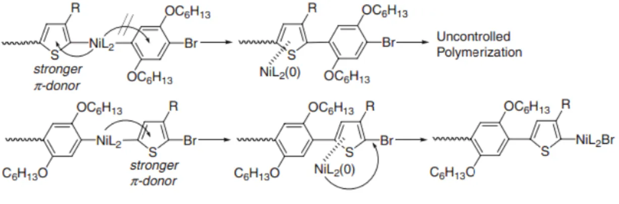
It is an important issue that which monomer should be polymerized first for successful synthesis of block copolymers. Yokozawa et al. demonstrated that the uncontrolled postpolymerization occurred while monomer of P3HT was polymerized first followed by monomer of poly(p-phenylene) (PPP). However, successful and well-controlled block copolymerization was carried out in the reverse sequence.10 The scheme is shown in Figure 1-7. It is associated with the π-donor ability of P3HT and PPP since the
13
π-electrons of the polymers are considered to assist the transfer of the Ni catalyst in GRIM polymerization. The thiophene ring has strong π-donor ability than the phenylene
ring. Therefore, it is difficult for catalyst to move to the terminal C-Br bond of phenylene ring for polymerizing the phenylene monomers while P3HT is polymerized first followed by PPP. The similar result was observed for synthesis of polyfluorene-b-poly(3-hexylthiophene) (PF-b-P3HT) using turbo GRIM reported by McCullough's group.11 More recently, novel heterocyclic block copolymers, poly(3-hexylseleophene)-b-poly(3-hexylthiophene) (P3HS-b-P3HT), was synthesized by Seferos's group.12 The morphology of P3HS-b-P3HT revealed clear phase separation with distinct domains according to their different heterocyclic constituents.
Figure 1-7 The synthesized sequence of PPP-b-P3HT by Grignardmetathesis.10
1-4 Self-assembly of conjugated polymer-containing block copolymers
Because of their special optical and electrical properties, conjugated polymers with rigid π-conjugated backbones have gained great interests in the region of polymer
science during the past few years. Recently, block copolymers containing conducting polymer segments, such as poly(p-phenylene) (PPP), polyfluorene (PF), poly(p-phenylenevinylene) (PPV) and polythiophene (PT), are technologically important since the incorporation of conjugated polymer into block copolymers with other functional coil-like polymers can generate distinct mechanical properties and provide novel approach for organic optoelectronic device fabrication. In order to optimize device performance from these structure-directing block copolymers, the definite self-assembly behavior of these conjugated block copolymers to precisely control active layer morphology and interfacial structure is greatly needed. Although the self-assembly behavior of conjugated block copolymers has attracted increasing attention for material science and nanofabrication purpose, the experimental studies for these novel materials are largely unknown.
Recently, there are some approaches which have performed to setup model system for conjugated block copolymers and illustrate their equilibrium thermodynamic phases.
Segalman et al. studied the self-assembling behavior of poly(2,5-di(2'-ethylhexyloxy)-1,4-phenylenevinylene)-b-polyisoprene (DEHPPV-PI)
15
and discuss their results with previous theoretical predictions.13, 14 On the basis of their
experimental results, lamellar structures are observed when the segregation strength between compositional blocks is weak or when the geometric asymmetry parameter (ν)
is low. On the other hand, non-lamellar phases such as hexagonal and spherical structures have been observed in the conditions of high asymmetry or increased segregation strength. Figure 1-8 shows the TEM images and Fourier Transforms of PPV-b-PI block copolymers. Furthermore, the resulting phase behavior derived from these observations is in a qualitative agreement with the theoretical calculations for rod-coil block copolymers since the PPV chains are perfect rigid rods, free of the molecular folding and conformational changes. Additionally, the recent work
contributed by Ho et al.15 has further discussed the phase diagrams in terms of the ratio of the rod-rod interaction (μ) to the rod-coil interaction (χ) in a
poly(diethylhexyloxy-p-phenylenevinylene-b-methylmethacrylate) (DEH-PPV-b- PMMA) system and showed the phase behavior of these copolymers (Figure 1-9). In 2005, McCullough and coworkers have reported that poly(3-hexylthiophene)-b-poly(3-dodecylthiophene) (P3HT-P3DDT) block copolymers were synthesized via a chain growth mechanism.16 Also, Hashimoto et al. reported the synthesis of poly(3-hexylthiophene)-b-poly[3-(2-ethylhexyl)thiophene]
(P3HT-b-P3EHT) block copolymer and demonstrated that these block copolymers can
self-assemble into a lamellar morphology in solid state.17 Meanwhile, Ueda et al. studies the poly(3-hexylthiophene)-b-poly(3-phenoxymethylthiophene) block copolymers system and observed the formation of nanophase-separated lamellar or sheet-like solid state morphologies.18
Among the various side chains modified conjugated polymers, the highly regioregular P3HT have received more attention since they show high crystallinity from main chain packing and excellent chemical stability and have been applied for photovoltaic and thin film transistors.19 P3ATs have been traditionally synthesized by electrochemical and oxidative polymerizations. However, these resultant polymers tend to be ill-defined with large polydispersities. Thus, Yokozawa et al. discovered that well-defined all-conjugated block copolymers with different main chains can be synthesized with low polydispersity via a chain growth mechanism. They reported the detailed synthesis on poly(2.5-dialkoxy-1.4-phenylene)-b-poly(N-hexyl-2.5-pyrrole) (PPy-b-PPP)20 and poly(2,5-dihexyloxy-p-phenylene)-b-poly(3-hexylthiophene) (PPP-b-P3HT)10 block copolymers. McCullough et al. discovered that well-defined end-functionalized P3HTs can be synthesized with low polydispersity via a chain growth mechanism by using the similiar catalyst-transfer polycondensation method.21 McCullough et al. further demonstrated that P3HT block copolymers can be synthesized from a linker molecule attached to an end-functionalized P3HT as a macroinitiator via
17
atom transfer radical polymerization (ATRP). They have found that thin and ultrathin films these block copolymers containing polythiophene that were prepared by casting from toluene followed by free evaporation of a solvent reproducibly self-assembled into well-defined nanowires, as shown in Figure 1-10.22
Figure 1-8 TEM images and Fourier Transforms of PPV-b-PI block copolymers. (a) PPVbPI-31, (b) PPVbPI-41, (c) PPVbPI-57, (d) PPVbPI-71, (e) PPVbPI-81, (f)
PPVbPI-87 and (g) PPVbPI-91. Fourier transforms of these polymers show that both have 6-fold symmetries characteristic of a hexagonal structure. (h) PPVbPI-87 and (i) PPVbPI-91.14
Figure 1-9 Phase behavior of PPV-b-PMMA block copolymers.15
Figure 1-10 Nanowire morphology in PS-P3HT block copolymers solvent-cast from toluene and visualized with tapping-mode AFM. Left: height image; right: phase image.22
19
1-5 Conjugated polymer/inorganic nanoparticles hybrid system
Polymer-inorganic hybrid materials include a broad variety of systems. For instance, a polymer can act as a matrix for dispersed inorganic nanoparticles thus constituting what is known by the name of nanocomposites. Besides other preparation methods, processes based on in situ particle synthesis including sol-gel processes have frequently been applied. Such methods can prevent agglomeration of inorganic species in the final products, which is often a problem when preformed nanoparticles and polymers are mixed, unless the particles are modified with an organic surface layer.
Importantly, polymer-inorganic hybrids can exhibit materials properties which are more pronounced or even differ from those of comparable polymer composites with larger inorganic particles, such as optical properties (e.g., transparency and color, including dichroism), magnetic properties (superparamagnetism), mechanical properties, chemical properties (catalytic or sensory activity), and gas barrier properties. Thus, polymer-inorganic hybrid materials are considered to find application in various areas, for example in photovoltaic cells, optics, sensor technology and electronic devices.
The conjugated polymer–inorganic semiconductor hybrid systems combine the advantages from both organic and inorganic materials. Conjugated polymers (e.g., P3HT), when self-organized into crystal structure, can own a high hole mobility, and can also be easily processed onto the surfaces of both rigid and flexible substrates.
Nanoscale inorganic materials exhibit different optical absorption and photocurrent generation properties from bulk materials due to their quantum size confinement. They have advantages including relatively high electron mobility, high electron affinity and good thermal stability. Solution-processible nanostructured inorganic semiconductors also provide the possibility to have a large interfacial area for efficient exciton dissociation when blending with soluble polymers.23 One-dimensional (1-D) ordered nanostructure inorganic semiconductors aligned on a substrate can provide an ideally straight pathway for carrier transport. Generally when organic and inorganic components are combined into a heterojunction device, the polymers are used as donors to absorb sunlight and transport holes, while the inorganic semiconductors CdSe function as acceptors to transport electrons. In such devices, an energy conversion efficiency exceeding 3% has been in reach.24 More recently, solid state dye-sensitized solar cell (DSSC) structure has been adopted to fabricate organic (polymer)-inorganic hybrid solar cells.25, 26 In these devices, the inorganic semiconductors (e.g., porous TiO2) are sensitized by a traditional dye or a light absorbing inorganic semiconductor (e.g., Sb2S3), and the polymers function as a hole transporter to reduce the dyes and/or also work as an additional donor to absorb light.27 A power conversion efficiency of 5.13%
has recently been achieved in this type of hybrid solar cells. The different functions of organic and inorganic materials provide additional opportunities to improve solar cell
21
performance by taking advantages of organic solar cells, inorganic semiconductor solar cells, and DSSCs. In general, because the interfacial charge separation is the critical step in the whole photovoltaic process, the larger the interfaces, the more the opportunity for the excitons to reach the interfaces, and probably the higher the conversion efficiency.
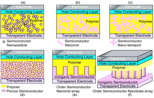
Therefore, most of the hybrid photovoltaic materials that have been studied are nano-structured composites. There are many types of nanostructures, including particles, rods, tubes, tetrapods, sheets, needles, and porous network, etc., and the way to mix the components together can be either disordered or ordered as shown in Figure 1-11.28
Figure 1-11 Various nano architectures of solar cell materials. (a) Blend of semiconductor nanoparticles and conducting polymer films; (b) blend of semiconductor nanorods and conducting polymer films; (c) blend of semiconductor nano-tetrapods and
conducting polymer films; (d) conducting polymer immersed in porous semiconductor nano-network; (e) blend of semiconductor nanorods arrays and conducting polymer films; and (f) blend of semiconductor nanotube arrays and conducting polymer films.28
1-6 Configuration and synthesis of TiO
2nanostructures
Titanium oxide, a wide band gap and n-type semiconductor, exists in three crystalline forms- anatase, rutile and brookite. The more important crystalline phases are anatase and rutile, which occur in atmosphere and are relatively easier to be prepared.29, 30 The phase transformation temperature between anatase and rutile is around 600 oC, as shown in the phase diagram of TiO2 (Figure 1-12).31
Both anatase and rutile phase of TiO2 belong to the tetragonal crystal system. The structures of anatase and rutile phase can be described in terms of chains of TiO6
octahedra. The main differences of these two structures are the distortion of each octahedron and the assembly pattern of the octahedra chains, as shown in Figure 1-13, which reveals the unit cell structures of the anatase and rutile crystals respectively.29 Each Ti4+ is surrounded by an octahedron of six O2- ions. The octahedron in both anatase and rutile phase is not regular, while the former has more orthorhombic distortion than the latter. Therefore, the symmetry of the crystal structure of anatase is
23
much lower than orthorhombic crystal system. For the assembly pattern of the octahedra chains in the anatase structure, each octahedron is in contact with eight neighbors-four sharing an edge and four sharing a corner. On the other hand, in the rutile structure each octahedron is in contact with ten neighbor octahedrons- two sharing edge oxygen pairs and eight sharing corner oxygen atoms. Figure 1-14 reveals the combination of chains of anatase and rutile phase.32 Moreover, the distances of Ti-Ti atoms in anatase are greater than those in rutile (3.79 and 3.04 Å for anatase; 3.57 and 2.96 Å for rutile), whereas the Ti-O distances in anatase are shorter than those in rutile (1.934 and 1.980 Å for anatase; 1.949 and 1.980 Å for rutile). These differences in lattice structures result in different mass densities and electronic band structures between anatase and rutile. The difference crystal structures of the two phases are listed in Table 1-2.30
Figure 1-12 The phase diagram of TiO2.31
Table 1-2 Properties of anatase and rutile phases of TiO2.30
Anatase Rutile
Crystal system Tetragonal Tetragonal
Lattice constant a 3.78 Å 4.58 Å
Lattice constant c 9.49 Å 2.95 Å
Specific gravity 3.9 4.2
Molar volume 20.156 18.693
25
Refractive index 2.52 2.71
Permittivity 5.5-6.0 6.0-7.0
Band gap energy
Melting point
3.2 eV Transforms to rutile
3.0 eV 1858 oC
Figure 1-13 Two kinds of TiO2 crystal structures: (a) rutile, (b) anatase.29
Figure 1-14 The combination of chains of (a) rutile and (b) anatase.32
Sol-gel process is the procedure that molecular precursors, e.g. metal chlorides or metal alkoxides, react with water, H2O, and form 3D metal oxide network via inorganic polymerization including hydrolysis and condensation reactions. Conventionally, aqueous sol-gel process, in which water is the solvent, is broadly used for the synthesis of titanium oxide bulk materials as well as nanoparticles. The reaction mechanisms of hydrolysis and condensation processes are shown in the following.33 Firstly, the
27
titanium alkoxide is hydrolyzed and an Ti-OH species is generated:
Hydrolysis
In the second step, the hydroxy groups react with each other or other metal alkoxide/chloride and a 3D M-O-M network is then formed upon the propagation of the condensation reaction and results in the elimination of ROH, water or HCl.
Condensation
The reaction mechanism of aqueous sol-gel process is rather simple. However, resulting from the high reactivity of the precursor towards hydrolysis,33 it has several disadvantages. For instance, the resulting products are often amorphous, which means that post thermal treatments are not avoidable to get crystalline material; the reaction parameters, such as temperature, pH, concentration of anions and even the method of mixing, have to be carefully controlled to achieve the desired products and reproducibility.
1-7 Configuration and synthesis of 1D ZnO nanostructures
One-dimensional (1D) nanostructured materials, such as nanorods, nanowires and nanobelts, have attracted much attention because of their special properties and wide potential applications in optoelectronic fields. Zinc oxide, as a wide bandgap
semiconductor (3.37 eV)34 and large excitation binding energy (60 meV),35 has attracted more and more interest in recent years. Moreover, ZnO is nontoxic, bio-safe material, and it is used in many biomedical applications. Therefore, because of ZnO possessing these numerous useful properties, it has been widely investigated for application in piezoelectric nanogenerators, piezoelectric transducers and actuators, surface acoustic coatings, chemical sensors, photonic crystals, solar cells,36 photocatalysts and so forth.
It has been reported that the properties of ZnO are closely depend on their dimensions and morphologies, including crystal size, aspect ratio, crystalline density and orientation.
Furthermore, highly oriented ZnO nanorods/nanowires are demonstrated having superior device performance as compared to nonaligned ZnO nanostructures.
ZnO nanostructures can be synthesize by using thermal evaporation process, radio frequency magnetron sputtering, chemical vapor deposition (CVD), metal-organic chemical vapor deposition (MOCVD), sol-gel reaction37, 38 and hydrothermal process.39 In the past few years, CVD, thermal deposition and hydrothermal process have been major methods to obtained one-dimensional ZnO nanostructure. The CVD and thermal