科技部補助專題研究計畫報告
新穎多功能二維奈米複合材料於能源與環境之應用-總計畫暨子
計畫一:超臨界流體一鍋合成法製備二維奈米複合材料及其在
能源儲存之應用(第3年)
報 告 類 別 : 成果報告 計 畫 類 別 : 整合型計畫 計 畫 編 號 : MOST 106-2221-E-006-170-MY3 執 行 期 間 : 108年08月01日至109年07月31日 執 行 單 位 : 國立成功大學材料科學及工程學系(所) 計 畫 主 持 人 : 丁志明 共 同 主 持 人 : 葉樹開、張高碩、阮至正計畫參與人員: post doctoral research-post doctoral research:1
本研究具有政策應用參考價值:■否 □是,建議提供機關
(勾選「是」者,請列舉建議可提供施政參考之業務主管機關)
本研究具影響公共利益之重大發現:□否 □是
中 文 摘 要 : 此研究著重於提高二氧化鈦的光催化性能,藉由結合其他的半導體 材料來增進二氧化鈦光觸媒。新型的三元TiO2/MoO3/g-C3N4奈米複 合光觸媒已被合成出來並且在亞甲基藍的降解上展現了direct dual Z-scheme 光降解機制。TiO2/MoO3/g-C3N4奈米複合催化劑表現優於 其組成成分,最高的降解速率常數達到0.0303 min-1,相比是 TiO2的3.9倍。優越的光催化能力歸因於g-C3N4和α-MoO3提高了可 見光的吸收與主要在TiO2和 α-MoO3中增加了光致電子電洞對的分 離和氧空缺的存在加快了電子傳輸,光降解機制利用direct dual Z-scheme來解釋。此研究對於設計出具有提升可見光吸收、有效率 的光致電子電洞分離和強還原能力的高效率Z-scheme光觸媒提出了 新的見解。
中 文 關 鍵 詞 : 中孔洞TiO2顆粒, g-C3N4, α-MoO3, Z-scheme, 光降 英 文 摘 要 : The main focus in this work is to enhance the
photocatalytic properties of TiO2. Enhancement of the TiO2 photocatalyst was done by incorporation another
semiconducting material. A novel ternary TiO2/MoO3/g-C3N4 nanocomposite photocatalyst has been synthesized and shown to exhibit a direct dual Z-scheme photodegradation
mechanism for methylene blue degradation. The TiO2/MoO3/g-C3N4 nanocomposite catalyst outperforms its constituents. The highest degradation rate constant of 0.0303 min-1 is about 3.9 times greater than that of TiO2. The improved photocatalytic activity is attributed to the enhanced visible light absorption from the g-C3N4 and α-MoO3, enhanced photogenerated hole/electron separation primarily in the TiO2 and α-MoO3, and enhanced fast charge transfer due to the existence of oxygen vacancies. The
photodegradation mechanism is explained using a direct dual Z-scheme. This work affords a new insight towards
designing highly efficient Z-scheme photocatalysts with enhanced visible light absorption, efficient photogenerated hole/electron separation, and strong redox ability.
英 文 關 鍵 詞 : TiO2 mesoporous beads, g-C3N4, α-MoO3, Z-scheme, photodegradation
科技部補助專題研究計畫成果報告
(□期中進度報告/
期末報告)
(計畫名稱)
計畫類別:□個別型計畫
整合型計畫
計畫編號:MOST 106-2221-E-006-170-MY3
執行期間:108 年 08 月 01 日至 109 年 07 月 31 日
執行機構及系所:
王宇豪/
工程司計畫主持人:丁志明
共同主持人:葉樹開、張高碩、阮至正
計畫參與人員:蘇費翠, 陳宏燊, 阮文成, 哈立德, 許至彥, 伊泰德, 林以芯
,
范育旻, 張俊鴻, 丁乃馨, 薩布維
本計畫除繳交成果報告外,另含下列出國報告,共 _0__ 份:
因武漢肺炎疫情影響,未執行國外研討會計劃以及報支差旅
□執行國際合作與移地研究心得報告
□出席國際學術會議心得報告
□出國參訪及考察心得報告
本研究
具有政策應用參考價值:
■否 □是,建議提供機關_______
(勾選「是」者,請列舉建議可提供施政參考之業務主管機關)
本研究具影響公共利益之重大發現:■否 □是
中 華 民 國 109 年 10 月 26 日
附件一I
Table of Contents
Abstract (English) ………...II Abstract (Chinese) ……….III
Introduction ………..1
Research Purpose ……….1
Experimental ………1
Results and Discussion ………....3
Conclusion ……….11
II
Abstract (English)
The main focus in this work is to enhance the photocatalytic properties of TiO2. Enhancement of the TiO2 photocatalyst was done by incorporation another semiconducting material. A novel ternary TiO2/MoO3/g-C3N4 nanocomposite photocatalyst has been synthesized and shown to exhibit a direct dual Z-scheme photodegradation mechanism for methylene blue degradation. The TiO2/MoO3/g-C3N4 nanocomposite catalyst outperforms its constituents. The highest degradation rate constant of 0.0303min-1 is about 3.9 times greater than that of TiO2. The improved photocatalytic activity is attributed to the enhanced visible light absorption from the g-C3N4 and α-MoO3, enhanced photogenerated hole/electron separation primarily in the TiO2 and α-MoO3, and enhanced fast charge transfer due to the existence of oxygen vacancies. The photodegradation mechanism is explained using a direct dual Z-scheme. This work affords a new insight towards designing highly efficient Z-scheme photocatalysts with enhanced visible light absorption, efficient photogenerated hole/electron separation, and strong redox ability.
III
Abstract (Chinese)
此研究著重於提高二氧化鈦的光催化性能,藉由結合其他的半導體材料來增進二氧化鈦光觸媒。新型 的三元 TiO2/MoO3/g-C3N4奈米複合光觸媒已被合成出來並且在亞甲基藍的降解上展現了 direct dual Z-scheme 光降解機制。TiO2/MoO3/g-C3N4奈米複合催化劑表現優於其組成成分,最高的降解速率常數 達到 0.0303min-1,相比是 TiO2的 3.9 倍。優越的光催化能力歸因於 g-C3N4和α-MoO3提高了可見光的 吸收與主要在 TiO2和 α-MoO3中增加了光致電子電洞對的分離和氧空缺的存在加快了電子傳輸,光降 解機制利用 direct dual Z-scheme 來解釋。此研究對於設計出具有提升可見光吸收、有效率的光致電子 電洞分離和強還原能力的高效率 Z-scheme 光觸媒提出了新的見解。
1
1. Introduction
Photocatalysts for hazardous waste remediation, air and water purification, deodorization, self-cleaning, and antibacterial application are receiving growing attention. Among the photocatalysts, it is recognized that although TiO2 has shown advantages, attention must be paid to its wide bandgap and rapid electron/hole recombination 1-5. As a result, heterojunction or Z-scheme design, typically involving the use of a second semiconducting material, is being widely investigated. However, in a heterojunction photocatalyst, the reduction ability of photogenerated electrons and oxidation ability of photogenerated holes are lower after the charge transfer. Therefore, the Z-scheme design has attracted greater attention because of its ability to not only reduce the rate of electron/hole recombination but also retain the redox ability 6-10. In a Z-scheme design, a guest semiconducting material with a lower conduction band (CB) and valence band (VB) is added to the host material. The photogenerated electrons in the CB of the guest semiconducting material are transferred to the VB of the host semiconducting material and recombine with the photogenerated holes. This results in the accumulation of photogenerated electrons giving strong reduction ability and photogenerated holes with strong oxidation ability in the CB of the host semiconducting material and the VB in the guest semiconducting material, respectively11. Several groups have thus reported a TiO2-based Z-scheme photocatalyst systems 12, 13.
In the recent years, another material, i.e., g-C3N4, has attracted tremendous attentions for photocatalyst application due to its low cost, high stability, visible-light response, and large scale production potential 14-16. However, g-C3N4 also suffers from its fast charge recombination. The addition of a guest material to reduce or prevent its fast charge recombination rate has been investigated. Silver nanoparticles (NPs) were used to form Ag/g-C3N4 composite for enhanced electrical conductivity 17. MoS2/g-C3N4 18 and CdMoO4/g-C3N4 heterojunctions 19, and CuInS2@C3N420, g-C3N4/TiO2 21, 22, and MoO3/g-C3N4 Z-schemes 23 have been studied. Among them, MoO3 is known as a semiconducting material with high chemical stability, non-toxicity, and higher electrical conductivity than others metal oxides. MoO3-based Z-scheme photocatalyst systems have been shown to improve the photocatalytic performance of a semiconducting material. MoO3/Bi2O4 Z-scheme was shown to enhance charge transfer and separation due to the strong interaction between the MoO3 and Bi2O4 24. Similarly, MoO3/g-C3N4 with a strong interfacial contact was also demonstrated for improved photodegradation performance 23. The synergistic effect of combining MnO2 nanorods and MoO3 nanoparticles was demonstrated with enhanced the charge separation 25. However, the single Z-scheme systems still show low visible light absorption and relatively low charge separation and transfer, thus giving moderate photodegradation efficiencies. Therefore, recently, dual Z-scheme systems, such as TiO2/g-C3N4/RGO 26, WO3/TiO2/rGO 27, and g-C3N4/Pd/TiO2 28, have become a focal subject. A dual Z-scheme system is composed of a conducting, a semiconducting, and a co-catalyst materials, giving further improvement of visible light adsorption, reduction of the charge separation, and keeping the strong redox capability.
2. Research Purpose
In this work, a novel dual Z-scheme ternary nanocomposite photocatalyst, namely, TiO2/MoO3/g-C3N4 nanocomposites, has been investigated. We investigated the very important relationship among processing, structure, and property, and performance of the novel TiO2/MoO3/g-C3N4 nanocomposites. The research starts with the investigation of their binary nanocomposites and continued with the ternary nanocomposites. The obtained nanocomposites were investigated for dye degradation.
3. Experimental
3.1 Fabrication of Single-component Catalysts
To make the TiO2/MoO3/g-C3N4 nanocomposites, TiO2 mesoporous beads, g-C3N4 NPs, and α-MoO3 nanorods were first synthesized individually as follows. A two-step method was used to make the TiO2 mesoporous beads 29, 30. In short, amorphous TiO2 particles was synthesized using a sol-gel method using titanium (IV) isopropoxide as the precursor, hexamethylenetetramine as the steric agent, and ethanol as the solvent. The obtained amorphous TiO2 particles were dispersed in deionized (DI) water and then subjected to microwave-assisted hydrothermal (MAH) treatment at 200 °C for 15 minutes to obtain TiO2 mesoporous beads. A thermal condensation method followed by a partial oxidation treatment using H2O2 31 was used to make the g-C3N4 NPs. Melamine powders were heated at 550°C (10°C min-1 heating rate) for 2 hours. The
2
obtained yellow powders were collected and ground using a mortar and pestle, and then subjected to the partial oxidation process. Briefly, 2 g of the yellow powders were dispersed in a solution consisting of 120 mL of isopropanol (CH₃CHOHCH₃) and 35 mL of H2O2. The suspension liquid was sonicated using a sonicator horn for 1 day at an on/off period of 9 s. The resulting suspension liquid was then centrifuged for several times to obtain the g-C3N4 NPs. α-MoO3 nanorods were also prepared using a MAH technique 32, 33. Typical experimental procedures are described below: 1.09 g of sodium molybdate dihydrate (NaMoO4.2H2O) was dissolved in 35 ml of DI water. Afterwards, hydrochloric acid was added into the solution under stirring to reach a pH value of 1 for the solution. The solution was subsequently subjected to MAH treatment at 180° for 10 min. At the end, white precipitates were formed at the bottom of the autoclave. The precipitate was then centrifuged and rinsed using ethanol and DI water for several times. α-MoO3 powders were collected after drying at 60° for 24 hours.
3.2 Fabrication of Binary and Ternary Nanocomposite Catalysts
TiO2 mesoporous beads/g-C3N4 NPs nanocomposites were obtained through an interfacial assembly strategy process. TiO2 mesoporous beads and g-C3N4 NPs were mixed in 30 mL DI water under stirring for 2 hours at 70°C. After that, the mixed powders were collected by centrifuging and drying the suspension at 60°C for 5 hours. The resulting powders were then calcined at 450 °C for 2 hours. TiO2 mesoporous beads/g-C3N4 NPs nanocomposites having various TiO2 to g-C3N4 mass ratios of 90:10, 60:20, 30:60, and 10:60 were prepared, giving Samples T9-CNH1, T6-CNH2, T3-CNH6, and T1-CNH6, respectively. To obtain the ternary TiO2/MoO3/g-C3N4 nanocomposite, binary MoO3/g-C3N4 nanocomposite was first fabricated by calcination of MoO3/g-C3N4 mixture at 400°C for 4 hours. After that, the MoO3/g-C3N4 nanocomposite was mixed with the TiO2 mesoporous beads through the same method used for preparing the binary TiO2 mesoporous beads/g- C3N4 NPs nanocomposite. In the ternary nanocomposites, the TiO2 to (MoO3+g-C3N4) mass ratio was fixed at 9:1, while the MoO3 to g-C3N4 mass ratios were 10:100, 20:100, 30:100, 40:100, and 75:100, giving Samples T-M10-CNH, T-M20-CNH, T-M30-CNH, T-M40-CNH, and T-M75-CNH, respectively.
3.3 Materials Characterization
The crystal structure of the resulting samples was investigated using X-ray diffractometry (XRD, Bruker AXS Gmbh, Karlsruhe, Germany) with a Cu-Kα radiation (λ = 0.15406 nm) at a scan step of 0.2/min from 10 to 70. The microstructure was investigated using scanning electron microscopy (FE-SEM, JEOL-6701F), operating at an accelerating voltage of 5kV. The SEM sample was prepared by first placing the material on a double-sided Cu tape, which was then subjected to 2-min Pt sputter deposition. The microstructure was also examined using transmission electron microscopy (TEM, JEOL JEM-2100F), operating at an accelerating voltage of 200kV. The TEM sample was prepared by dispersing the material into an ethanol solution. Afterward, the dispersion was drop-casted on lacey 300 mesh Cu grid and dried in the vacuum oven at 60C for overnight.
The surface chemistry was investigated using X-ray photoelectron spectroscopy (XPS, VG Scientific ESCALAB 250 and ULVAC-PHI PHI 5000 Versaprobe II) having a monochromatic Al K X-ray beam. The XPS sample was prepared by pressing the powders onto a double-sided Cu tape, which was then attached onto a glass substrate. The obtained XPS spectra were corrected for the surface chargingto the C1s peak at its maximum intensity at a binding energy of 284.6 eV. The curve fitting was performed using the XPSPeak41 software with a Shirley fit for the background and 50%Lorentzian-50%Gaussian for the curve fitting. The N2 adsorption/desorption isotherms were obtained at 77K using a Micromeritics Tristar II 3020 apparatus. The specific surface area was determined using the Brunauer-Emmet-Teller (BET) method and the pore size distributions were derived from the desorption isotherms using the Barret-Joyner-Halenda (BJH) method. UV-visible spectroscopy (UV-Vis, Perkin Elmer LAMBDATM 950 UV/VIS/NIR) was used to examine the light absorption. The wavelength range used was from 350 to 800 nm. The UV-vis sample was prepared by placing the powders in between two glass substrates. Photoluminescence (PL) spectroscopy (PerkinElmer LS-55 fluorescence spectrometry) with an excited Laser wavelength of 320 nm was used to investigate the emission property. The PL sample were prepared by pressing the powders onto a double-sided Cu tape and then the tape was attached onto a glass substrate.
3.4 Photocatalytic Degradation Test
3
Firstly, 20 mg of photocatalyst was well dispersed in 50 mL of MB solution (20 ppm). Prior the photodegradation, the suspension was vigorously stirred in dark condition for 30 minutes. The degradation of MB was performed under the irradiation of a 235 W Xe lamp. During the photodegradation process, a small amount of the suspension was collected using a syringe every 10 minutes then centrifuged to completely remove the photocatalyst. Subsequently, the MB concentration of the resulting solution was analyzed using UV-vis spectrometry. The MB degradation rate was determined using the equation of C = (Co-C)/Co, where the Co and C are the MB concentrations after the dark reaction and after the light irradiation, respectively. The total time for the photodegradation was 90 minutes. Following the first order kinetics, the equation of -ln(C/Co) = Kappt was used to determine the apparent first-order rate constant (Kapp) after an irradiation time (t). Trapping experiments were also carried out in the presence of four radical scavengers, including p-benzoquinone (BQ), isopropanol (IPA), ethylenediaminetetraacetic acid (EDTA), and K2S2O8, as the superoxide radicals (•O2−), hydroxyl radicals (•OH), holes (h+), and electrons (e−) scavengers, respectively. The above photodegradation experiments were conducted with 1 mM of BQ, EDTA, or K2S2O8, or 5 mL of IPA.
3.5 Electrochemical Impedance Spectroscopy (EIS) Measurement
EIS measurement was performed in a Shanghai Chenhua CHI-660D electrochemical system using a three-electrode cell, consisting of a working electrode, a 0.5 M Na2SO4 solution as the electrolyte, a Pt plate as the counter electrode, and an Ag/AgCl as the reference electrode. To make the working electrode, a slurry was prepared by dispersing 5 mg of the catalyst in a solution consisting of 150 μl of ethanol, 350 μl of deionized water, and 50 μl of Nafion (5wt%). 10 μl of the resulting slurry was drop-casted onto a 1 x 1 cm2 ITO glass, which was then dried at 60C for 6 hours to form the working electrode. The EIS measurement was performed in a frequency range between 105 and 0.1 Hz with an amplitude of 10 mV.
4. Results and Discussion
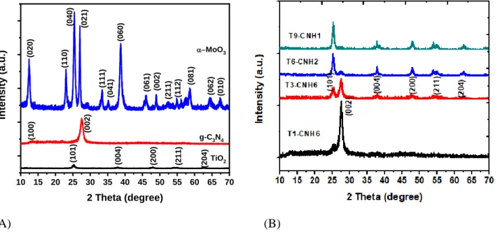
Figure 1 (A) shows the XRD patterns of the obtained TiO2 mesoporous beads, g-C3N4 NPs, and MoO3 nanorods. The TiO2 exhibits an anatase phase; while the MoO3 has an phase. After mixing the TiO2 beads with the g-C3N4, XRD analysis shows that the binary nanocomposite consists of TiO2 and g-C3N4 phases with respective peak intensity increases with the percentage of the pertinent phase (Figure 1B).
10 15 20 25 30 35 40 45 50 55 60 65 70 (204 ) (211 ) (200 ) (004 ) (101 ) (211 ) (112 ) (010 ) (062 ) (081 ) (002 ) (061 ) (060 ) (041 ) (111 ) (021 ) (040 ) (110 ) (020 ) (002 ) In te n si ty ( a. u .) 2 Theta (degree) TiO2 g-C3N4 -MoO3 (100 ) (A) (B)
Figure 1. XRD patterns of (A) the obtained TiO2 mesporous beads, g-C3N4, and MoO3 nanorods and (B) TiO2/g-C3N4 nanocomposites.
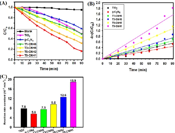
However, the addition of g-C3N4 into the TiO2 enhances the photodegradation efficiency (Figure 2A). The photodegradation kinetics were determined by plotting ln(C/C0) vs. the irradiation time (Figure 2B). The
4
calculated rate constants are shown in Figure 2C. It shows that the addition of g-C3N4 enhances the photodegradation.
Figure 2. Photodegradation (A) efficiency, (B) kinetics, and (C) reaction rate constants of TiO2/g-C3N4 nanocomposites.
PL emission spectra of the g-C3N4, TiO2, and TiO2/g-C3N4 nanocomposites were therefore examined (Figure 3A). The deconvoluted PL emission spectra of the TiO2/g-C3N4 nanocomposites are shown in Figures 3B. The T1 and T2 peaks average at 373±1.0% and 416±2.8% nm, respectively; while the C1, C2, and C3 average at 437±1.9%, 463±3.6%, and 497±2.4% nm, respectively. It was found that the degradation efficiency in general improves with the T1 and T2 emissions (designated as T emission) of the TiO2, and the C2 and C3 emissions (designated as C emission) of the g-C3N4, as shown in Figure 3C. This indicates that the photodegradation performance is enhanced with reduced PL peak intensity, suggesting suppression of the electron/hole recombination through a Z-scheme mechanism as discussed later. The photodegradation performance also increases and decreases with decreasing and increasing Ti4+/Ti3+ ratio, respectively, as shown in Figure 3D. The existence of oxygen vacancies leads to enhanced conductivity for improved charge separation.
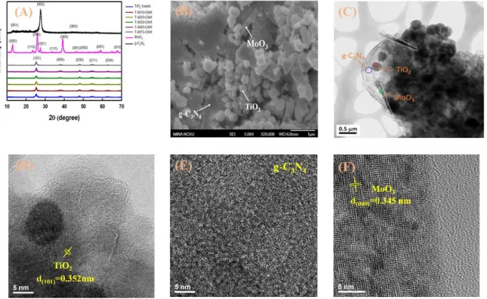
For the ternary TiO2/MoO3/g-C3N4 nanocomposites, XRD analysis shows only diffraction peaks belonging to the anatase TiO2 but not the g-C3N4 and α-MoO3 due to their minor amounts (Figure 4A). The existence of all three constituents is shown in SEM image (Figure 4B). Figure 4C further shows intimate contacts among the constituents, favoring charge transfer. Figures 4D to F show HR-TEM images of each constituent. Figure 4D shows that the TiO2 beads contain nanograins with an average diameter of 10 nm. The d-spacing of 0.352 nm corresponds to the (101) plane of anatase TiO2. Figure 4E shows that the g-C3N4 is amorphous; while Figure 4F shows that the d-spacing of the -MoO3 is 0.345 nm. The specific surface area and porosity of nanocomposites were investigated using N2 adsorption analysis. Figure 5 shows the N2 adsorption-desorption isotherms and pore size distribution of selected samples. The TiO2 and its nanocomposites exhibit type IV-isotherms according to the Brunauer–Deming–Deming–Teller (BDDT) classification, indicating the existence of mesopores (Figure 5A). The isotherm curves also exhibit a H1 adsorption hysteresis loop, suggesting that the N2 adsorption occurs in a narrow-ranged uniform mesopores 34. The BJH method was further used to determine the pore size distribution. Figure 5B shows the existence of
5
the mesopores in the binary and ternary nanocomposite. Similarly, the TiO2 beads also have mesopores as we reported previously 35. The BET surface area of the TiO2 was determined to be 150.6 m2 g-135, which is higher than that of T9-CNH1 (73 m2 g-1) and T-M30-CNH (121.9 m2 g-1). The addition of g-C3N4 blocks the pores in the TiO2, thus resulting in a lower surface area. On the other hand, it appears that the addition of MoO3 unblocks the pores. The results confirm that the obtained nanocomposites having mesopores and large surface areas are beneficial for the adsorption of the organic pollutant.
Figure 3. (A) PL spectra of g-C3N4, TiO2, and TiO2/g-C3N4 and (B) detailed analysis of the PL spectra of T9-CNH1. (C) Fraction of MB left vs. T2, C2, C3 peak intensities. (D) Fraction of MB left vs oxygen vacancies.
6
Figure 4. (A) XRD patterns, (B) SEM, and (C) TEM images of ternary TiO2/MoO3/g-C3N4 nanocomposite (T-M30-CNH). HR-TEM images of (D) TiO2 fromthe red circle in C, (E) g-C3N4 from the blue circle in C, and (F) MoO3 from the green circle in C. The white dashed lines highlight the MoO3 nanorods.
(A) (B)
Figure 5. (A) N2 adsorption-desorption isotherms and (B) pore size distribution of TiO2 and its nanocomposites.
The g-C3N4 and α-MoO3 in the ternary nanocomposites were further examined using XPS analysis. Figure 6A shows the survey spectra of the TiO2/MoO3/g-C3N4 nanocomposites, indicating the existence of C, O, N, Mo, and Ti in the ternary nanocomposites. High resolution XPS spectra of Ti2p, Mo3d, C1s, O1s, and N1s were also obtained, as shown in Figures 6B, 6C, 6D, and 6E, respectively, for T-M30-CNH. The Ti2p spectrum (Figure 6B) shows peaks near 458.6 and 464.4 eV, belonging to the Ti2p 3/2 and Ti2p 1/2 for Ti4+, respectively. It also shows peak at lower binding energies of 458.2 and 463.5 eV, belonging to Ti2p 3/2 and Ti2p 1/2 for Ti3+, respectively. With the addition of MoO
3, the oxygen vacancies in the TiO2 appear to vary. The Ti4+/Ti3+ ratio determined for the binary TiO2/g-C3N4 nanocomposite (T9-CNH1) is 1.21; while that for the ternary TiO2/MoO3/g-C3N4 nanocomposites ranges from 1.00 to 1.65. High-resolution Mo3d spectrum (Figure 6C) shows that there are Mo6+, Mo5+, and Mo4+ in the TiO
7
peaks near 235.16 and 232.1 eV are attributed to the Mo3d 3/2 and Mo3d 5/2 for Mo6+, respectively. Two peaks near 234.3 and 231.4 eV are assigned to the Mo3d 3/2 and Mo3d 5/2 for Mo5+, respectively. Two peaks near 233.3 and 230.4 eV are attributed to the Mo3d 3/2 and Mo3d 5/2 for Mo4+, respectively. The existence of Mo5+ and Mo4+ indicates that there are oxygen vacancies in the MoO3. Also, the appearance of Mo4+ suggest a reduction of MoO
3 to form MoO2, which was not observed in the sample without TiO2, (M75-CNH1). The Ti4+/Ti3+ and Mo6+/(Mo5++M4+) ratios, representing the oxygen vacancy levels in TiO2 and MoO3, respectively, were then examined. Figure 7 shows the ratios vs. the MoO3 fraction. The oxygen vacancy in the TiO2 is either less or more than that in the sample without MoO3, i.e., T9-CNH1; while the oxygen vacancy in the MoO3 increases, as compared to the sample without TiO2, i.e., M75-CNH. The reduction of MoO3 is apparent as that the Ti4+/Ti3+ data exhibits concave-up and the Mo6+/(Mo5++M4+) data is concave-down shapes (Figure 7).
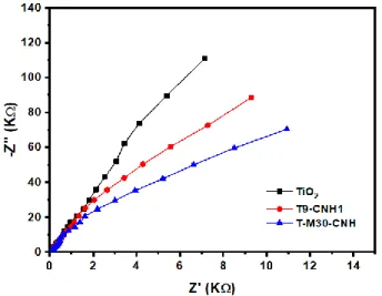
Figure 8A shows the UV-visible absorption spectra of the TiO2/MoO3/g-C3N4 nanocomposites. Figure 8B shows the PL spectra of the ternary TiO2/MoO3/g-C3N4 nanocomposites. The addition of MoO3 reduces the PL intensity, indicating reduced electron/hole recombination. However, too much MoO3 (T-75M-CNH) results in severe recombination. It is believed that excessive MoO3 would give extra recombination sites, thereby increasing the PL intensity. After deconvolution, in addition to the T1 (375±0.6% nm), T2 (399±1.5% nm), C1 (440±0.4% nm), C2 (457±0.4% nm), and C3 (484±0.3% nm), one more peak at 421±0.6% nm, designated as M, is seen, as shown in Figure 8C for the T-M30-CNH. The M peak is from the indirect transition in the MoO3 36. The charge separation in the nanocomposites is further discussed using EIS analysis. A smaller semicircle in a Nyquist plot indicates a lower charge transfer resistance (Rct), thus resulting in a more efficient charge separation. Figure 9 shows that the Rct of the T-M30-CNH is smaller than that of the T9-CNH1, followed by TiO2. The enhanced electrical conductivity, as compared to the T9-CNH1 and TiO2, also leads to reduced charge recombination in the T-M30-CNH ternary nanocomposite. The enhanced electrical conductivity of the ternary nanocomposite is due to the formation of oxygen vacancies in both the TiO2 and MoO3, as discussed above.
Figure 6. XPS (A) survey spectra of TiO2/MoO3/g-C3N4 nanocomposites. High resolution XPS spectra of (B) Ti2p, (C) Mo3d, (D) C1s, (E) O1s, and (F) N1 of T-M30-CNH.
8
Figure 7. Ti4+/Ti3+ and Mo6+/(Mo5++M4+) ratios vs. the MoO3 fraction. The upper horizontal line represents the Ti4+/Ti3+ ratio in the binary TiO2/g-C3N4 nanocomposite (T9-CNH1) and the lower horizontal line represents the Mo6+/(Mo5++M4+) ratio in the MoO3/g-C3N4 binary nanocomposite (M75-CNH).
Figure 8. (A) UV-visible absorption and (B) PL spectra of the ternary TiO2/MoO3/g-C3N4 nanocomposites, and (C) deconvoluted PL spectra of T-M30-CNH.
Figure 9. EIS spectra of TiO2 and its nanocomposites.
Figure 10A shows the photodegradation performance of the ternary nanocomposites. The photodegradation kinetics and rate constants of the ternary nanocomposites are shown in Figures 10B and C, respectively. The rate constant of the ternary T-M30-CNH nanocomposite (0.0303 min-1) is 1.6 and 3.9 times greater than that of the binary T9-CNH1 nanocomposite (0.0189 min-1) and TiO
2 (0.0078 min-1), respectively. The photodegradation efficiency increases with the addition of MoO3 up to 2.3 wt% (T-M30-CNH), showing an efficiency of 95%. The efficiency decreases when the MoO3 is more than 2.3
9
wt%. This is accompanied by the reduced PL emissions in all three constituents and the increased conductivity in the TiO2. Figure 11A shows that the MB left increases (decreases) with increased (decreased) T, C, and M emissions. Moreover, as in the binary nanocomposites, the conductivity of the TiO2 dominates. Figure 11B shows that the MB left increases and then decreases with the Ti4+/Ti3+ ratio but does not correlate well to the Mo6+/(Mo5++Mo4+) ratio. Trapping experiment was carried out to identify the main oxidative species during the photodegradation of MB. Figure 12 shows that the EDTA significantly decreases the photodegradation efficiency; while the other three scavengers (BQ, IPA, and K2S2O8) exhibit less efficiency decreases. To be exact, the photodegradation efficiency of MB follows the order of no scavenger > K2S2O8 IPA BQ > EDTA. Thus, the trapping experiment result indicates that the h+ is the main oxidative species during the MB degradation in the presence of the ternary nanocomposite; while e-, •OH, and •O2− also exist but exhibit lesser roles during the photodegradation. As discussed below, the photogenerated holes are accumulated in the VB of the TiO2 and MoO3, contributing to the high efficiency of photodegradation.
Figure 10. Photodegradation of MB under solar irradiation in the presence of ternary TiO2/MoO3/g-C3N4 nanocomposites. (A) Efficiency, (B) kinetics, and (C) reaction rate constants.
Figure 11. (A) The photodegradation efficiency vs. the TiO2 (T), g-C3N4 (C), and MoO3 (M) emissions, and (B) the oxygen concentrations in TiO2 and MoO3.
10
Figure 12. Photocatalytic degradation of MB under solar irradiation by ternary TiO2/MoO3/g-C3N4 nanocomposites in the presence of different scavengers.
A plausible dual Z-scheme photodegradation mechanism is proposed. We first consider the binary nanocomposite. The photodegradation performance of binary TiO2/g-C3N4 nanocomposite is enhanced with reduced Ti4+/Ti3+ ratio or increased oxygen vacancy, i.e., increased conductivity of the TiO2, as illustrated in Figure 3C. This indicates that the TiO2 dominates the photodegradation. Therefore, a Z-scheme mechanism is proposed. The band edge positions of the TiO2, g-C3N4, and MoO3 are shown in Figure 13. The valence band position, EVB, was determined using EVB = X - Ee + 0.5Eg, where X, Ee, and Eg are the absolute electronegativity of semiconductor, the free electron energy in hydrogen scale (~4.5), and the bandgap of the semiconductor, respectively 37. The Eg of TiO2, g-C3N4, and MoO3 were determined from the Tauc plots to be 3.38, 2.84, and 3 eV, respectively (Figure 13A). Thus, the EVB are 3, 1.62, and 3.4 eV for the TiO2, g-C3N4, and MoO3, respectively. The conduction band position, ECB, equals EVB - Eg, giving -0.38, -1.22, and 0.40 eV for the TiO2, g-C3N4, and MoO3, respectively. For the binary TiO2/g-C3N4 nanocomposite (Figure 13A), when solar light irradiates on the TiO2, the photogenerated electrons are transferred from the VB to the CB. With the existence of g-C3N4, some of the photogenerated electrons in the CB of the TiO2 are transferred to the VB of the g-C3N4, as indicated by Z emission in Figure 13A, thus reducing the aforementioned T and C emissions, in turn, reducing the recombination. As a result, the degradation of MB occurs at the VB of the TiO2 through both reaction of the MB with the photogenerated holes and the formed hydroxyl radical (∙OH) from the H2O. The degradation also occurs at CB of the g-C3N4 by the reaction between the MB and the ∙OH from O2. In other words, the binary nanocomposite follows a Z-scheme degradation mechanism. A similar mechanism occurs in the ternary TiO2/MoO3/g-C3N4 nanocomposites between the TiO2 and g-C3N4, except a second Z-scheme occurs due to the presence of MoO3, as shown in Figure 13B. In the first Z-scheme, the photogenerated electrons in the CB of the TiO2 are transferred to the VB of the g-C3N4, represented by the Z1. In the second Z-scheme, the MoO3 generates holes at the VB and electrons at the CB during light irradiation. The photogenerated electrons in the MoO3 combine with the photogenerated holes in the g-C3N4,represented by the Z2. In the second Z-scheme, the degradation of the MB occurs through direct reaction of the MB with the photogenerated holes and the ∙OH in the VB of the TiO2 and MoO3; while at the CB of the g-C3N4 by the reaction between the MB and the ∙OH from O2 occurs to degrade the dye. As mentioned above, the holes are the main oxidative species during the MB degradation. The holes and active radical species of ∙OH and ∙O2- participate in the degradation of MB according to the following reaction.
h+/•OH/•O
11
Figure 13. (A) Tauc plots of TiO2, g-C3N4, and MoO3. Photocatalytic degradation mechanism in the presence of (B) TiO2/g-C3N4 (single Z-scheme) and (C) TiO2/MoO3/g-C3N4 (dual Z-scheme).
It is therefore concluded that the ternary TiO2/MoO3/g-C3N4 nanocomposite exhibits a direct dual Z-scheme which effectively enhances the photocatalytic performance to the TiO2. The dual Z-scheme gives not only an efficient charge separation for each material but also photogenerated holes with strong oxidation ability in the VB of TiO2 and MoO3, as well as photogenerated electrons with strong reduction ability in the CB of g-C3N4. The photocatalytic performance of TiO2 based photocatalyst are shown in Table 1. It shows the visible light photodegradation efficiency enhancement through the addition of MoO3/g-C3N4 in to the TiO2. Only small amount of TiO2/MoO3/g-C3N4 catalyst is needed to have better catalytic performance as compared to others.
Table 1. Comparison representation of the photocatalytic performances of TiO2-based photocatalysts. Catalysts Photocatalytic
applications
Mass of catalyst (mg)
Light source Photocatalytic activity
Refs.
TiO2@g-C3N4 RhB solution; (10 mg L-1, 30 mL)
40 300 W Xe-arc lamp 93.3% removal within 100 min 14 C-TiO2/ g-C3N4 MO solution; (20 mg L-1, 50 mL) 50 300 W Xe lamp 98% removal within 60 min 38 g-C3N4/ TiO2 RhB solution; (10 mg L-1, 30 mL) 30 500 W Xe lamp 84% removal within 5h 39
g-C3N4/ TiO2 Phenol solution; (50 mg L-1, 1000 mL) 1000 300 W UV–vis arc lamp 85% removal within 120 min 40 g-C3N4/ TiO2 Isoniazid solution; (50 mg L-1, 500 mL) 100 - 90.8% removal within 250 min 41 g-C3N4quantum dots / TiO2 RhB solution; (5 mg L-1, 50 mL) 50 500 W Xe lamp ~95% removal within 4h 15
TiO2/MoO3 RhB solution; (10 mg L-1, 70 mL)
70 500 W Xe lamp 91.49% removal after 150 min
12 TiO2/MoO3/g-C3N4 (T-M30-CNH) MB solution; (20 mg L-1, 50 mL) 20 235 W Xe lamp 95% removal within 90 min This work
5. Conclusion
A novel dual Z-scheme TiO2/MoO3/g-C3N4 nanocomposite photocatalyst has been synthesized through mechanical mixing followed by calcination. We first show that binary TiO2/g-C3N4 reduces the charge recombination in the TiO2 through a Z-scheme mechanism. The addition of α-MoO3 into the TiO2/g-C3N4 adds a second Z-scheme such that the resulting ternary TiO2/MoO3/g-C3N4 nanocomposite exhibits a dual Z-scheme photodegradation mechanism. Based on trapping experiment and the dual Z-scheme mechanism, the holes were found to be the main oxidative species during the MB degradation. It was also found that the existence of oxygen vacancies reduces the charge transfer resistance to give efficient charge separation. As a result, excellent photocatalytic performance to degrade MB is achieved for ternary TiO2/MoO3/g-C3N4 nanocomposite with a degradation efficiency up to 95% and a reaction constant of 0.0303min-1, which is 1.6 and 3.9 times greater than that of binary T9-CNH1 nanocomposite and TiO2, respectively.
6. References
1. F. Zhang, J. Zhao, T. Shen, H. Hidaka, E. Pelizzetti and N. Serpone, Appl. Catal. B-Environ., 1998, 15, 147-156.
2. N. Serpone and A. V. Emeline, J. Phys. Chem. Lett., 2012, 3, 673-677.
3. D. Wang, Y. Xu, F. Sun, Q. Zhang, P. Wang and X. Wang, Appl. Surf. Sci., 2016, 377, 221-227. 4. Y. Zuo, J. Chen, H. Yang, M. Zhang, Y. Wang, G. He and Z. Sun, J. Mater. Chem. C, 2019, 7,
9065-9074.
5. R. A. Rakkesh, D. Durgalakshmi and S. Balakumar, J. Mater. Chem. C, 2014, 2, 6827-6834.
6. L. Jiang, X. Yuan, G. Zeng, J. Liang, X. Chen, H. Yu, H. Wang, Z. Wu, J. Zhang and T. Xiong, Appl.
Catal. B. Environ., 2018, 227, 376-385.
7. D. P. Ojha, H. P. Karki, J. H. Song and H. J. Kim, Compos. Part B Eng., 2019, 160, 277-284. 8. M. Jourshabani, Z. Shariatinia and A. Badiei, J. Mater. Sci. Technol., 2018, 34, 1511-1525. 9. M. Tang, Y. Ao, P. Wang and C. Wang, J. Hazard. Mater., 2020, 387, 121713.
10. Z. Li, X. Wang, J. Zhang, C. Liang, L. Lu and K. Dai, Chin. J. Catal., 2019, 40, 326-334.
11. R. Shen, L. Zhang, X. Chen, M. Jaroniec, N. Li and X. Li, Appl. Catal. B Environ., 2020, 266, 118619. 12. Y. Gong, Y. Wu, Y. Xu, L. Li, C. Li, X. Liu and L. Niu, Chem. Eng. J., 2018, 350, 257-267.
13. Y. Wang, C. Zhu, G. Zuo, Y. Guo, W. Xiao, Y. Dai, J. Kong, X. Xu, Y. Zhou, A. Xie, C. Sun and Q. Xian, Appl. Catal. B Environ., 2020, 278, 119298.
14. L. Ma, G. Wang, C. Jiang, H. Bao and Q. Xu, Appl. Surf. Sci., 2018, 430, 263-272.
15. Y. Li, K. Lv, W. Ho, F. Dong, X. Wu and Y. Xia, Appl. Catal. B Environ., 2017, 202, 611-619. 16. Y. Li, K. Lv, W. Ho, F. Dong, X. Wu and Y. Xia, Appl. Catal. B. Environ., 2017, 202, 611-619. 17. F. Chen, H. Yang, W. Luo, P. Wang and H. Yu, Chin. J. Catal., 2017, 38, 1990-1998.
18. X. Lu, J. Xie, X. Chen and X. Li, Appl. Catal. B Environ., 2019, 252, 250-259. 19. B. Chai, J. Yan, G. Fan, G. Song and C. Wang, Chin. J. Catal., 2020, 41, 170-179. 20. J. Luo, Z. Lin, Y. Zhao, S. Jiang and S. Song, Chin. J. Catal., 2020, 41, 122-130.
21. J. Huang, D. Li, R. Li, P. Chen, Q. Zhang, H. Liu, W. Lv, G. Liu and Y. Feng, J. Hazard. Mater., 2020,
386, 121634.
13
23. S. Adhikari and D.-H. Kim, Appl. Surf. Sci., 2020, 511, 145595.
24. T. Jiang, K. Wang, T. Guo, X. Wu and G. Zhang, Chin. J. Catal., 2020, 41, 161-169. 25. H. Salari, J. Photochem. Photobiol. A Chem., 2020, 401, 112787.
26. L. Hu, J. Yan, C. Wang, B. Chai and J. Li, Chin. J. Catal., 2019, 40, 458-469. 27. F. He, A. Meng, B. Cheng, W. Ho and J. Yu, Chin. J. Catal., 2020, 41, 9-20.
28. Y. Guo, L. Xiao, M. Zhang, Q. Li and J. Yang, Appl. Surf. Sci., 2018, 440, 432-439. 29. C.-R. Ke and J.-M. Ting, J. Power Sources, 2012, 208, 316-321.
30. C.-R. Ke, L.-C. Chen and J.-M. Ting, J. Phys. Chem. C, 2012, 116, 2600-2607.
31. C.-W. Chu, F. N. I. Sari, J. C.-R. Ke and J.-M. Ting, Appl. Surf. Sci., 2018, 462, 526-539. 32. F. N. Indah Sari and J.-M. Ting, Electrochim. Acta, 2019, 320, 134533.
33. F. N. Indah Sari, Y.-C. Liu and J.-M. Ting, Compos. B. Eng., 2019, 177, 107355.
34. T. Matthias, K. Katsumi, V. N. Alexander, P. O. James, R.-R. Francisco, R. Jean and S. W. S. Kenneth,
Pure Appl. Chem., 2015, 87, 1051-1069.
35. M. E. Purbarani, F. N. I. Sari and J.-M. Ting, Surf. Coat. Technol., 2019, 378, 125073.
36. N. Illyaskutty, S. Sreedhar, G. Sanal Kumar, H. Kohler, M. Schwotzer, C. Natzeck and V. P. M. Pillai,
Nanoscale, 2014, 6, 13882-13894.
37. S. Adhikari, H. H. Lee and D.-H. Kim, Chem. Eng. J., 2019, DOI: https://doi.org/10.1016/j.cej.2019.123504, 123504.
38. Z. Lu, L. Zeng, W. Song, Z. Qin, D. Zeng and C. Xie, Appl. Catal. B Environ., 2017, 202, 489-499. 39. Z. Tong, D. Yang, T. Xiao, Y. Tian and Z. Jiang, Chem. Eng. J., 2015, 260, 117-125.
40. C. Miranda, H. Mansilla, J. Yáñez, S. Obregón and G. Colón, J. Photochem. Photobiol. A Chem., 2013,
253, 16-21.
41. W.-K. Jo and T. S. Natarajan, Chem. Eng. J., 2015, 281, 549-565.
14
科技部補助專題研究計畫成果彙整表
計畫主持人:丁志明 計畫編號:MOST 106-2221-E-006 -170 -MY3
計畫名稱:新穎多功能二維奈米複合材料於能源與環境之應用--總計畫暨子 計畫一:超臨界流體一鍋合 成法製備二維奈米複合材料及其在能源儲存之 應用 成果項目 量化 單位 質化 (說明:各成果項目請附佐 證資料或細項說明,如期刊 名稱、年份、卷期、起訖頁 數、證號...等) 國 內 學術性論文 期刊論文 0 篇 請附專書資訊。 研討會論文 1
“Thermal interface materials having hybrid fillers for enhancing
through-thickness thermal conductance and increasing electrical resistance” TACT2019. Poster. 專書 0 本 請附專書資訊。 專書論文 0 章 請附專書論文資訊。 技術報告 0 篇 其他 0 篇 國 外 學術性論文 期刊論文 6 篇
1. Applied Surface Science 533 (2020) 147506. 2. Journal of American
Ceramics Society 103 (2020) 2252.
3. Surface & Coatings Technology 378 (2019) 125073. 4. Composite Part B: Engineering 177 (2019) 107355. 5. Ceramics International 45 (2019) 23651–23657. 6. Electrochimica Acta 320 (2019) 134533. 研討會論文 0 專書 0 本 請附專書資訊。 專書論文 0 章 請附專書論文資訊。 技術報告 0 篇 其他 0 篇 參 本國籍 大專生 0 人次 1. Exfoliate g-C3N4 using 附件三
15 與 計 畫 人 力 碩士生 3 supercritical fluid machine.
2. Exfoliate the MoS2 using the supercritical fluid machine. 博士生 0 專任人員(博士級) 0 專任人員(非博士級) 0 非本國籍 大專生 0 碩士生 5 博士生 2 專任人員(博士級) 1 專任人員(非博士級) 0 其他成果 (無法以量化表達之成果如辦理學術活動、獲得獎項、 重要國際合作、研究成果國際影響力及其他協助產業 技術發展之具體效益事項等,請以文字敘述填列。)
106年度專題研究計畫成果彙整表
計畫主持人:丁志明 計畫編號:106-2221-E-006-170-MY3 計畫名稱:總計畫暨子計畫一:超臨界流體一鍋合成法製備二維奈米複合材料及其在能源儲存之應用 成果項目 量化 單位 質化 (說明:各成果項目請附佐證資料或細 項說明,如期刊名稱、年份、卷期、起 訖頁數、證號...等) 國 內 學術性論文 期刊論文 0 篇 研討會論文 1“Thermal interface materials
having hybrid fillers for enhancing through-thickness thermal
conductance and increasing
electrical resistance” TACT2019. Poster. 專書 0 本 專書論文 0 章 技術報告 0 篇 其他 0 篇 國 外 學術性論文 期刊論文 6 篇
1.Applied Surface Science 533 (2020) 147506.
2.Journal of American Ceramics Society 103 (2020) 2252.
3.Surface & Coatings Technology 378 (2019) 125073.
4.Composite Part B: Engineering 177 (2019) 107355. 5.Ceramics International 45 (2019) 23651–23657. 6.Electrochimica Acta 320 (2019) 134533. 研討會論文 0 專書 0 本 專書論文 0 章 技術報告 0 篇 其他 0 篇 參 與 計 畫 人 力 本國籍 大專生 0 人次 碩士生 3 林以芯 范育旻 丁乃馨 博士生 0 博士級研究人員 0 專任人員 0 非本國籍 大專生 0 碩士生 5 陳宏燊
許至彥 伊泰德 張俊鴻 薩布維 博士生 2 阮文成 哈立德 博士級研究人員 1 蘇費翠 專任人員 0 其他成果 (無法以量化表達之成果如辦理學術活動 、獲得獎項、重要國際合作、研究成果國 際影響力及其他協助產業技術發展之具體 效益事項等,請以文字敘述填列。)