行政院國家科學委員會專題研究計畫 成果報告
亞熱帶熱濕氣候區低密度住宅導入尖端熱環境控制技術之 研究-以台科一號開放性實驗屋為例--總計畫兼子計畫 四:亞熱帶熱濕氣候區低密度住宅導入尖端熱環境控制技
術之研究-以台科一號開放性實驗屋為例 研究成果報告(精簡版)
計 畫 類 別 : 整合型
計 畫 編 號 : NSC 98-2221-E-011-128-
執 行 期 間 : 98 年 08 月 01 日至 99 年 10 月 31 日 執 行 單 位 : 國立臺灣科技大學建築系
計 畫 主 持 人 : 江維華
共 同 主 持 人 : 魏浩揚、李孟杰
計畫參與人員: 博士班研究生-兼任助理人員:王家瑩 博士班研究生-兼任助理人員:許皓香 博士後研究:黃建勝
報 告 附 件 : 出席國際會議研究心得報告及發表論文
處 理 方 式 : 本計畫可公開查詢
中 華 民 國 100 年 01 月 20 日
1
行政院國家科學委員會補助專題研究計畫 □
ˇ成果報告
□ 期 進度 報 告
亞熱帶熱濕氣候區低密度住宅導入尖端熱環境控制技術之 研究-以台科一號開放性實驗屋為例
計畫類別:□ 個別型計畫
□
ˇ 整合型計畫 計畫編號:NSC 98-2221-E-011-128執行期間:98 年 08 月 01 日至 99 年 10 月 31 日
總計畫主持人:江維華 國立台灣科技大學建築系教授 子計畫主持人:江維華 國立台灣科技大學建築系教授
魏浩揚 國立台灣科技大學建築系副教授
李孟杰 國立台中技術學院室內設計系助理教授 計畫參與人員:黃建勝、王家瑩、許皓香
成果報告類型(依經費核定清單規定繳交):
□
ˇ精簡報告 □完整報告本成果報告包括以下應繳交之附件:
□赴國外出差或研習心得報告一份
□赴大陸地區出差或研習心得報告一份
□
ˇ出席國際學術會議心得報告及發表之論文各一份□國際合作研究計畫國外研究報告書一份
處理方式:除產學合作研究計畫、提升產業技術及人才培育研究計畫、
列管計畫及下列情形者外,得立即公開查詢
□涉及專利或其他智慧財產權,□一年□二年後可公開查詢
執行單位:國立台灣科技大學建築系
中 華 民 國 99 年 1 月 19 日
附件一
2
亞熱帶熱濕氣候區低密度住宅導入尖端熱環境控制技術之 研究-以台科一號開放性實驗屋為例
Implementing Cutting-edge Thermal Control Technologies on Low-density Residential Building in Hot-humid Climate – A
Case Study of NTUST 1 Experimental House
計畫編號:NSC 98-2221-E-011-128
執行期限:98 年 08 月 01 日至 99 年 10 月 31 日 主持人:江維華 國立台灣科技大學建築系教授
計劃參與人員:黃建勝 國立台灣科技大學建築系博士後研究員 王家瑩、許皓香 國立台灣科技大學建築系研究生
中文摘要
本研究以開放式獨立住宅為實驗平 台,進行建築構造與環境控制系統的整合 性研究,建築構造系統提供了配合實驗的 環境條件與可調式構造,環境控制系統則 整合被動與主動控制系統,包括地底恆溫 利用、輻射制冷技術整合室內通風系統 等,進行同步與整合性之性能與效益檢 討。整體研究成果希望能針對亞熱帶熱濕 環境氣候,提出適用於低密度住宅之最佳 化複合式熱環境控制技術,並期望該系統 能同步降低環境負荷與整體生命週期之耗 能與成本。
關鍵字:開放式建築、複合熱環境控制、
地冷系統、輻射冷房系統、通風系統
Abstract
The research project is proposed to conduct an experiment of thermal control system based on an existing experimental house building. The building is designed to provide adaptable use and required physical environment for the experiments. The environment is an integrated passive and active control system that utilizes ground source, radiant chiller system, and indoor ventilation strategies. After some polite testing and tuning, the work is to monitor the performance of the proposed optimization and to assess the system based on criteria concerning sustainability. The results of the proposed research will improve the understanding of the feasibility of optimizing a hybrid thermal control
system for subtropical, hot-humid climate.
The established system is aimed to reduce the environmental loading, energy consumption and cost of the building life cycle.
Keywords: open building, hybrid thermal environment control, ground cooling, radiant cooling ceiling, ventilation system
一、前言
在世界幾種主要氣候區中,寒帶、溫 帶、與熱乾氣候區都能有效率的提供舒適 的室內環境,唯獨台灣所處的濕熱氣候 區,被動式手法的應用有其極限,在夏季 高 溫 高 濕 的 條 件 下 , 必 須 仰 賴 主 動 式 (active)冷房,才能同時移除顯熱與潛熱負 荷,而這些主動式機械基本上都需耗費相 當的能量。常用的主動冷房設施雖有直 流、變頻、變流量、變風量等節能模式之 開發,近年來換氣造成的冷房負荷也可藉 由已經商品化的全熱交換器(ERV, energy recovery ventilator)來降低耗能,然而在實 務的應用上,當代的節能建築除了要以被 動與可變(adaptive)手法優先來整合高效 能的主動式設備之外,也必須能積極的整 合再生能源系統,才能有效的降低耗能。
針對環太平洋區域的舒適性研究顯示 該區域的居民對熱有較高的耐受性,這些 研究改變了長期使用美國 ASHRAE 以北 美所制定的舒適標準,對國內的建築節能 設 計 有 正 面 的 意 義 。 對 室 內 空 氣 品 質 (indoor air quality)的重視,也形成了將換 氣與冷房分開處理的觀念。若將此觀念融
3
入本研究中,則自然通風提供了主要換氣 與污染物移除的需求,地中管提供了預冷 與三分之一換氣的功能,而輻射冷房為供 應室內主要冷源及舒適的熱環境。
中庭建築的熱環境直接影響到中庭健 康、舒適的使用功能,應採用經濟、合理 的通風手段對其進行控制,以帶走室內的 二氧化碳,並稀釋有害氣體、微粒等污染 物濃度。目前,自然通風作為一種節省能 源的通風模式,在中庭建築中受到越來越 多的重視和應用,然而相對應的溫度場研 究並不多。本研究針對小型建築的中庭空 間進行了 CFD 模擬,同時利用計算流體力 學和熱傳學的方法對該建築進行了數值模 擬和理論分析,以期描述自然通風作用下 中庭的溫度場與氣流場特點,為中庭自然 通風設計提供依據。
近 年 來 地 冷 (earth cooling) 與 地 暖 (earth heating)之應用在世界各地的傳統建 築都可發現,地源的利用在世界上以中緯 度地區最為普遍,主要是因為地溫過低或 過高時,使用的價值都不高。地中管(earth tube)技術是一種較為便利的地源利用。在 地溫較高的地區,地中管雖然不容易完全 的取代主動式冷房,但可搭配置換式通風 的概念,能有效的引入冷卻的新鮮空氣,
節省 20%至 30%的空調耗能。
濕熱氣候區的台灣,當夏季室外溫度 高過 31℃且濕度超過 80%的條件下,必須 仰賴機械式或其他的主動式冷房,才能同 時移除顯熱及潛熱的熱負荷,達到適合人 體工作的舒適環境。而濕熱型氣候的國家 使用自然通風(natural ventilation)、誘導式 通 風 (induced ventilation) 、 機 械 式 通 風 (mechanical ventilation)、混合通風(mixing ventilation)及輻射冷卻系統(radiant cooling system)等方式來幫助改善室內使用空間 的環境品質,其中又以輻射冷卻併用置換 通 風 系 統 (displacement ventilation) 的 方 式,更能達到室內均溫、舒適及省能的環 境。
本研究所得的結果將整合於開放式建 築物(台科一號開放性實驗屋)作為實驗平 台(圖 1)。春秋季節以自然通風為基礎,並 提供主動控制地底恆溫利用;夏季則導入 輻射冷房降溫,結合三者的研究成果,進
行整合性效益檢討,建立開放式室內熱環 境實驗之綜合評估。
圖1 台科一號結合主被動式手法示意圖 二、文獻探討
1996 年 Campell 提 出 以 經 濟 (economy)、生 態(ecology) 與平等(equity) 三個要素構成的永續發展模型,三者缺一 不可。在建築表現上,生態的訴求在技術 層面為節能、健康、與環保,其中以節能 與全球面臨的能源枯竭及氣候變遷有著最 重要的關係。
永續發展在建築的實質應用上,包含 了相當複雜的專業知識與技術領域。國際 上許多建築師事務所也陸續以設計永續、
共生概念的建築為訴求,知名者如英國的 Foster and Partners 、 Future System 、 Llewelyn Davies Yeang 等。當許多建築師 將具備永續特性的建築實際蓋出來的同 時,結合學界、產業界、與官方的力量仍 持續著挑戰新的訴求,也因此產生了許多 實驗屋,代表性案例如 80 年代英國的「夢 幻之屋」、90 年代日本的「Next21」、Rolf Disch 會旋轉太陽能屋、2000 後瑞士的
「Swiss House」、與澳洲的「House of the Future」等。在台灣則有台大的「綠房子」、 成大的「孫運璿零碳綠建築」大樓及台科 大的「台科一號」、「MEGA House」和即 將興建完成的「台灣建築科技中心」實驗 性大樓等。這些建築物的訴求各有不同,
包括能源使用、開放性利用、與建材循環、
智慧化控制等,但節能或再生能源使用都 是主要訴求之ㄧ,也特別因氣候之不同而 具地域性的特色。
三、研究目的
春秋自然通風
地中管系統結合全熱交換器 地源熱泵系統
輻射制冷
4
建築設計與設備必須能反映季節轉換 時節能策略的改變,外氣溫度適宜的春秋 季或夏季的夜間可結合各種自然或加上輔 助設備之通風手法移除室內的熱量與濕 氣;夏季外氣溫度高時,換氣量則須加以 控制,以避免增加額外的熱負荷,大量的 換氣僅限於移除蓄積於構造體的熱量,換 氣量造成的冷房(顯熱與潛熱)負荷也可以 利用一些特殊的技術降到最低,以上目標 的達成則必須仰賴主被動手法的良好搭 配,下一章節則為此研究之對策與進行步 驟。
四、研究方法
其進行步驟如下:
1. 利用 CFD 數值解析的方法,對影響中 庭自然通風換氣量以及中性帶高度的 各項因素進行研究與分析。探討浮力通 風與風力通風對於抬高中庭室內氣流 場的影響。應用 CFD 電腦模擬解析進 行改變中庭通風窗高度、開口形式、開 口面積、室內熱源類型、通風路徑、中 庭抬高高度及室外風速等因素,藉由通 風量及室內平均溫度的評估,提供中庭 自然通風設計的參考。
2. 地中管的實驗研究顯示地底年平均溫 度約介於 23 至 24℃的恆溫,經由建築 能源解析軟體 TRNSYS 模擬兩根 5m 的鋁合金材質地中管,以串聯的型式安 裝,並用正壓的方式在固定送風量下,
由外管 流經管 壁與土 壤進 行熱交換 後,求得內管氣流的出風溫度,藉此評 估結合建築物後之可行性。
3. 輻射冷房部分的研究,主要分為實驗與 模擬兩個部份,實驗部份探討不同板面 進水溫 度及流 量對於 室內 氣溫的影 響,再進一步將實驗所得到之數據配合 CFD 數值模擬軟體,來計算輻射冷板 數量、表面溫度及送氣方式,對於室內 環境熱舒適度的分佈。分析方式是以 ASHRAE 的舒適度指標來評估其 PMV 值是否落在舒適度範圍內。
五、結果與討論 1. 自然通風
在自然通風方面,先以一簡化之矩形
體模擬自然通風時的情形。觀察圖 2 可看 出,當室外風速愈大,位在受風面處的進 風口負壓愈明顯,形成的風壓換氣也愈 強;在中庭通風窗對角配置且進風口設置 於 受 風 面 負 壓 處 時 , 當 室 外 風 速 小 於 1.5-2m/s,風壓與依溫度差造成之浮力相 抵消,使換氣效果降低;當室外風速達到 2m/s 時,風壓換氣大於浮力換氣,中庭內 的通風路徑則由風壓換氣支配,此時,部 分自然風由出風口貫入,與室內溫度差造 成之浮力相抵消,也因逆流使室內形成渦 流的情形,造成室內平均風速雖然有明顯 的提高,但是對於室內排熱的效果卻沒有 比無外風場時來的好。要補足此缺點,可 以在出風口的前面豎立擋風板,利用風的 負壓吸出室內空氣,提高換氣量。觀察圖 3 發現,當室外風速到達 2m/s,室內會形 成渦流,造成出風口的排熱效果減低。室 外風速微弱時,風壓換氣擾亂了原本浮力 換氣的上升氣流,使整體的換氣量比無外 風場時明顯減少許多,進而降低了室內排 熱的效果,造成室內的平均溫度明顯比無 外風場時升高許多。
圖2 不同室外風速之壓力場與氣流場 CFD數值解析結果
5
圖 3 不同室外風速之溫度場 CFD 數值解 析結果
2. 地冷系統
本研究初期採用氣循環式地中管系 統,設備部分採用兩根 5m 地中管、箱型 風機、全熱交換器以及輔助用分離式冷氣 如圖 4。在初始室溫 30℃的情況下,使室 內回風 30℃之風溫打進 5m 深的地中管,
藉由地底較地表冷的特性來降低溫度後 送入室內。至於全熱交換器是藉由室內初 始氣溫 30℃與外氣 35℃進行熱交換後接 近 32℃送入室內,同時排氣的部份也將室 內受汙染之空氣一併帶出,其作用在於保 持室內空氣之潔淨。經由地中管送入室內 之風溫與全熱交換器送入之風溫 32℃混 合,使原本室內初始溫度下降達舒適範 圍,運轉後持續降溫。而分離式冷氣系統 則是當室內熱負荷過大時,輔助氣循環式 地中管系統的降溫設備,並可提供除濕功 能。圖 5 為空氣流經地中管系統模擬圖,
模擬結果由圖 6 可知,在七月時 30℃之外 氣流經地中管 6 小時後溫度漸趨穩定,且 出風溫度約可降至 27.5℃,已達室內預冷 效果。
圖 4 氣循環式地中管系統配置圖
圖 5 外氣流經地中管系統模擬圖
圖 6 外氣流經地中管出風溫度曲線 3. 輻射冷房
在輻射冷房實驗的部份,採用 T-型熱 電偶線量測溫度。溫度量測資料擷取採用 Campbell Scientific , Inc.出產 CR10X 型資 料擷取器搭配熱偶線之類比訊號。熱影像 擷取採用 FLIR i60 紅外線熱像儀,來估算 輻射冷板表面放射率以及觀察大面積輻射 冷板之溫度變化如圖 7。圖 8 為當室內初 始溫度 28.5℃±0.2℃,濕度控制在 50%左 右,無出風空室的情形下,內部熱負荷由 燈源及牆體之對流和傳導熱所提供,利用 實驗量測不同輻射冷板進板水溫與流量對 室內溫度之影響。綜合實驗結果發現,板 面進水 溫 度 高 於 20℃以 上冷 卻能力不 足,導致室內溫度無法下降,即使進水流 量達 100LPM 也無法有效降低室溫。當板 面進水溫度 18℃時室內溫度開始下降,在 流量 100LPM 時得到該組室內溫度最低 值。若板面進水溫度在 16℃,流量 100LPM 時可達到最低室內溫度,但板面已開始有 結露現象產生,因表面放射率改變,則室
6
內降溫能力也會隨之受影響。
輻射冷板 燈 管
冷板溫度
圖 7 輻射冷板進水 18℃之板面溫度分 佈
(a) (b)
(c) (d)
圖8 (a)-(d) 輻射冷板水溫搭配不同流量之 室內溫度
在輻射冷房模擬的部份,針對板量與 板溫變化來探討室內空間之冷卻效益及熱 舒適性。圖9為單純使用輻射冷板,不依靠 送氣降溫的條件下,使用者產生的高溫向 上浮力流,遇到表面溫度較低的輻射冷 板,氣流往兩邊散逸的情形,此時輻射冷 板以輻射及對流兩種熱傳機制與使用者進 行熱交換來達到降溫的效果。只有單純使 用輻射冷板時室內均溫性良好,但均未達 人體舒適度範圍,因此採用外氣輔助出風 系統來增加冷卻能力。圖10為增加18℃下 出風後的情形,採用置換通風的送氣概念 在空間裡產生層化現象,並對使用區域直 接降溫,低溫之輻射冷板則是提供了室內
溫度的均勻性,人體與設備等熱源產生之 上升氣流也能同時帶走汙染物,此時模擬 之室內平均溫度為21.87℃。
圖 9 使用區域的自然對流情形(無送氣,輻 射冷板表面溫度為 18℃)
圖 10 輻射冷板搭配置換通風的室內溫度 分佈(送氣溫度 18℃,輻射冷板表面溫度
18℃) 六、結論
本研究已經完成各項技術之初期成 果,可導入開放式低層獨立住宅平台(台科 大土城校區-台科一號實驗屋),探討以被 動式控制手法為優先,結合主動式熱環境 控制策略,環境控制系統則導入適合於低 密度地區使用之地溫利用技術、輻射冷房 與自然通風機制。整體研究在建築設計與 設備上能反映季節轉換時,節能策略的改 變,並且經由本案建立建築跨領域統整研 究之模式,整合建築、土木、機械與環工 等專業研究人力,建構符合永續發展目標 的熱環境控制系統評估指標與實質評價方 法,並將成果納入專業課程,進一步達到 教育訓練的目的。
七、參考文獻
[1] Abdeen Mustafa Omer (2008),
7
“Ground-source heat pumps systems and applications,” Renewable and Sustainable Energy Reviews, 12, 344–371.
[2] Alamdari, F. (1998), “Chilled ceiling and displacement ventilation,”
Renewable Energy, 15, 300-305.
[3] Allard, F. and Santamouris, M. (1998), Natural Ventilation in Buildings, Earthscan Publications Ltd.
[4] Atila Novoselac and Jelena Srebric (2002), “A critical review on the performance and design of combined cooled ceiling and displacement ventilation systems,” Energy and Buildings, 34 (5), 497-509.
[5] Christopher L. Conroy and Stanley, A.
Mumma (2001), “Ceiling radiant cooling panels as a viable distributed parallel sensible cooling technology integrated with dedicated outdoor air systems,” ASHRAE Transactions, 107(1), 578-585.
[6] Florides, G. and Kalogirou, S. (2007),
“Ground heat exchangers—A review of systems, models and applications,”
Renewable Energy, 32, 2461–2478.
[7] Holford, J. M. and Hunt, G. R. (2003),
“Fundamental atrium design for natural Ventilation,” Building and Environment, 38(3), 409-426.
[8] Hunt, G. R. and Linden, P. P. (1999),
“The fluid mechanics of natural ventilation—displacement ventilation by buoyancy-driven flows assisted by wind,” Building and Environment,
34(6), 707-720.
[9] Li, X., Chen, Y., Chen, Z. H., Zhao J.
(2006), “Thermal performances of different types of underground heat exchangers,” Energy and Buildings, 38, 543–547.
[10] Nikolas Kyriakis, Apostolos Michopoulos, and Konstantin Pattas (2006), “On the maximum thermal load of ground heat exchangers,” Energy and Buildings, 38, 25–29.
[11] Popiel C., Wojtkowiak J., and Biernacka B. (2001), “Measurements of temperature distribution in ground,”
Exp. Therm. Fluid Sci., 25, 301–309.
[12] Rees, S.J. (2001), “Numerical investigation of transient buoyant flow in a room with a displacement ventilation and chilled ceiling system,”
Int. J. Heat Mass Transfer, 44(16), 3067-3080.
[13] Rees, S.J. and Haves, P. (2001), “A nodal model for displacement ventilation and chilled ceiling systems in office spaces,” Building and Environment, 36(6), 753-762.
[14] Solaini, G., Dall’O’, G., and Scansani, S. (1998), “Simultaneous application of different natural cooling technologies to an experiment building,” Renewable Energy, 15, 277-282.
[15] Stanley, A. Mumma (2001), “Radiant cooling panel systems,” ASHRAE Journal, 43(11), 28-32.
[16] Stanley, A. Mumma (2002), “Chilled
8
ceilings in parallel with dedicated outdoor air systems: addressing the concerns of condensation, capacity, and cost,” ASHRAE Transactions, 108(2), 220-231.
[17] Stanley, A. Mumma (2002), “Safety and comfort using DOAS radiant cooling panel systems,” ASHRAE IAQ Applications newsletter, winter, 1-2.
[18] Stetiu, Corina (1998), Radiant cooling in US office buildings: towards eliminating the perception of climate-imposed barriers, Energy and Resources Group, University of California at Berkeley Press.
[19] Wong, N. H. and Heryanto, S. (2004),
“The study of active stack effect to enhance natural ventilation using wind tunnel and computational fluid dynamics (CFD) simulations,” Energy and Buildings, 36, 668-678.
[20] Wu, H. J., Wang, S. W., and Zhu, D. S.
(2007), “Modelling and evaluation of cooling capacity of earth–air–pipe systems,” Energy Conversion and Management, 48, 1462–1471.
八、計畫成果自評
本研究內容與原計畫相符程度達 90%
以上,在有限的經費補助下已盡力達成預 期目標,研究成果之學術價值共發表國外 SCI 國際期刊一篇(審查中),國際研討會六 篇(其中含兩篇 EI),及五篇國內研討會。
至於創新應用技術整合自然通風、地源冷 暖技術及輻射冷房系統,於台科大土城校 區之台科一號開放性實驗屋,其研究過程 包含實驗和模擬兩部份,探討以被動式控 制手法為優先,結合主動式熱環境控制技
術,所得的結果可導入亞熱帶熱濕氣候區 之低密度住宅,對於國家社會整體節能策 略有長足的助益。由於研究資源的限制,
部份的研究成果僅能完成電腦數值模擬,
期冀未來能獲得更多的研究經費抑注,得 以做進一步的深入性研究。
2010 澳洲國際室內聲學研討會心得報告
江維華
台灣科技大學建築系
一、參加會議經過
本次受補助參加之會議為每三年舉行之第十二屆國際聲學大會(ICA,
International Congress on Acoustics)之衛星會議,也是每三年舉辦之國際室內聲學研 討會(ISRA, International Symposium on Room Acoustics),地點在澳洲墨爾本市,會 場設於墨爾本表演藝術中心的會議廳。本次會議由國際聲學委員會(International Commission for Acoustics)與澳洲聲學學會所共同主辦,國際聲學委員會主要是以會 員國的方式加入,主要成員為高度開發之工業國。
本次會議為期三天,在九月 29 日上午開幕,緊湊的議程由九個場次構成,包含 舞台聲學、主客觀評定、音樂廳設計新觀念、計算室內聲學、擴散與擴散材等主題,
共有約 90 篇的論文發表,論文分三類,三篇大會專題講座、一篇晚宴講座、25 篇 邀請發表論文、與約 60 篇的投稿論文,投稿論文除海報外並做三分鐘的簡短口頭發 表。筆者的第一篇發表為受邀發表論文,於九月 29 日上午在「舞台聲學」以口頭方 式發表論文「梯田式音樂廳之舞台聲學特質」(Stage Acoustics for Vineyard Concert Halls) (附件一),主要報告在遠比鞋盒型音樂廳寬的梯田式音樂廳之舞台環境特徵,
以及可能用來改善其不利舞台反射環境的方法,探討對象包括舞台位置、席位分割 方式、上方懸吊反射板、上層牆面與天花板等,並解此論述舞台聲場與觀眾席聲場 設計之互動關係。第二篇發表為投稿論文,於九月 30 日上午在「音樂廳設計新觀念」
場次做摘要報告,題目為「一個是用交錯梯田式席位之中型音樂廳」(A mid-size concert hall with staggered terraced seating)(附件二),為一個 1200 席音樂廳設計個案 之報告,該案以一個具環繞廳堂特質的古典鞋盒型廳堂為藍本,然後逐步推演出具 備其聲場優點之中型梯田式廳堂,並搭配其非對稱之建築物配置使用交錯的梯田式 席位設置。
二、與會心得
1. 舞台聲學 – 音樂廳舞臺音響環境因為設計機能性、美學性、與心理性之需求,加 上其主觀評定過程遠較觀眾席之評定來得困難,因此直到 90 年代才有較清楚的認 知,在 21 世紀初量測反射音與距音源 1m 遠直接音的比值-支持度成為 ISO 規範中
的一項評定參數,但由於舞臺環境的需求是多向度的,本次研討會因此有專門的 場次對此做探討。除筆者發表的論文之外,其他論文則涉及對樂團整體印象的評 價、樂手間在需求上的差異,以及過低的反射板造成的音染色問題等。但由當前 發展,可發現仍有以下議題值得繼續探討:(1)聲部間需求的差異(2)樂手台、樂團 配置等之影響(3)擴大之樣本已進行多向度研究等,因此本次參與此場次之發表者 將在研討會後繼續探討進行整合性研究之可能性。
2. 樂團演出之聲場虛擬技術 – 大型音樂廳以團體演出為主,包括交響樂團、大型 合唱團等,長久以來由於樂團的錄音不易且電腦解析無法不易反應各種樂器之指 向性特質,虛擬樂團演出通常使用單點聲源來製作。近年來由於對樂器聲源特值 得進一步掌握,加上提供對各種專業耳機之頻譜修正,以及運算速度之大幅提 升,本次會議中已有研究單位結合了出版擬真軟體之廠商,製作了樂團演出之多 軌無響錄音。在運用雙頻道輸出的前提下,配合各個樂器之聲場運算,未來將可 直接應用於製作虛擬聲場,反應樂團作為一個面音源之臨場感。
三、參觀活動
研討會安排了兩場參觀,各為墨爾本市整修中的大音樂廳與甫開幕的獨奏廳。
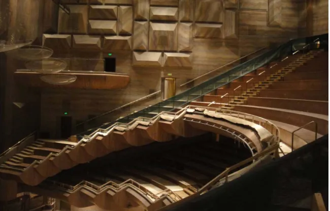
1. 整修中的大型音樂廳漢默廳(Hamer Hall)位於墨爾本表演藝術中心,鄰近於本次 會議地點。該廳興建於 1982 年,為 2661 席之專用音樂廳(如圖 1 所示),但由於 席位容量過大導致某些席位有明顯的聲學上缺陷,例如整體能量不足、夾層席位 因兩側初挑過深導致餘響感不足等。整修工程已在進行中,預計於 2012 年重新 開幕。室內聲學上的改善包括縮減整體廳堂寬度、減少兩側包廂的出挑、重做舞 台上方反射板等,其他配合的改善包括更新風管與出回風口以降低空調之機械噪 音,以及增加舞台上之機械設施以提供跨界演出等,座位容量將縮減至 2500 席 以下。
2. 新建之墨爾本獨奏廳(Melbourne Recital Center)具表演藝術中心約 500 尺,2009 年開幕,1003 席的空間以室內樂與中小型樂團演出為主要機能(如圖 1 所示),但 舞台兩側旋轉開之活門可提供簡易之劇場功能,增加表演上之多樣性,約 140 m2 的舞台可容納 70 人的樂團。該廳以鞋盒型為基本平面型狀,但前後端各做斜角 處理以增加初期反射能量,室內的另一大特色則是模仿木頭紋理做層深凹凸,以 達擴散的目的,在這些隨機的紋理之外,舞台的周邊與觀眾席後強更增加了模矩 化的凹凸,增加其擴散效果。
四、結語
本次研討會的議程緊湊且充實,能深刻體認當前國際上室內聲學上的進展,也 可以感覺到學界與業界在研發上的高度互動,如此才能提升技術競爭力。希望未來 能持續參與此系列研討會的核心活動,進而爭取會議之主辦權。
圖 1.墨爾本表演藝術中心漢默廳側面影像
圖 2. 墨爾本獨奏廳舞台正面全景
Proceedings of the International Symposium on Room Acoustics, ISRA 2010 29-31 August 2010, Melbourne, Australia
ISRA 2010 1
Stage acoustics for vineyard concert hall
Wei-hwa Chiang, Yi-run Chen, Chia-chun Chen, and Yen-kun Hsu
National Taiwan University of Science and Technology 43, Keelung Rd. Section 4, Taipei 106, Taiwan, R.O.C
PACS: 43.55 FW
ABSTRACT
In rectangular concert halls all surfaces near the stage can be valuable for acoustical communication among perform- ers, while in a vineyard hall the ceiling may become the only surface to provide early reflections back to the stage.
Field measurement and subjective evaluation in a hall with adjustable overhead panels were performed regarding the effectiveness of the reflectors for various parts of an orchestra. Results of computer modeling were presented that compares various design features intended for enhancing early and late energy back to the performers. Also pre- sented were the discussion regarding the interaction between the parameters for the musician and the parameters for the audience.
INTRODUCTION
The presence of “vineyard” style of concert halls is growing because of the dynamic atmosphere created in such a style of hall [1]. Besides normally noticed difficulties due to source directivity, problems associated with early support may arise when walls are farther away from each other in compared with a rectangular hall. Overhead reflectors become a popu- lar solution to this problem.
This paper explored the issues of on-stage acoustics associ- ated with vineyard halls. Various design factors employing computer simulation were analysed in attempt to better under- stand the design techniques to mitigate the difficulties.
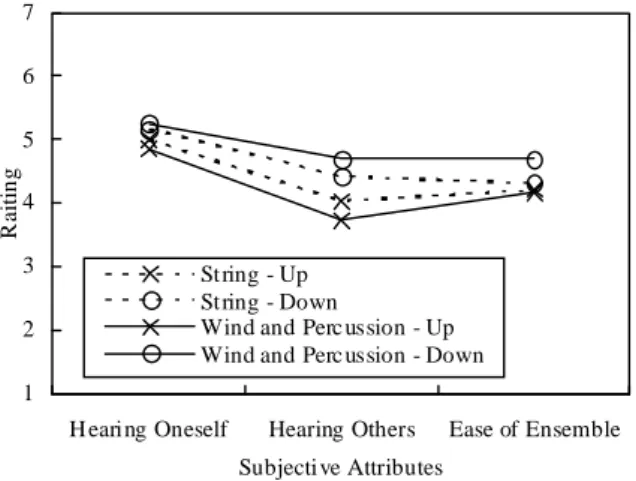
Figure 1. Subjective rating as a function of attributes com- paring the configuration with the reflector arrays up position (╳) to down position (○) and the string section (dotted lines)
to the wind and percussion sections (solid lines).
EARLY ENERGY
The results of some unpublished early study of field meas- urement and subjective evaluation in a 2,200-seat, 32-m wide multi-purpose hall [2] were presented to show how different players react differently. Arrays of triangular, adjustable overhead panels were installed over the front half portion of the stage. An oriental orchestra that used both western and eastern instruments played various orchestral pieces with the reflector arrays set to 7.5 m and 12 m high above the stage.
Average early support (STearly) measured at solo and cello position for the two reflector configurations were -14.9 dB and -16.1 dB, respectively. The value at the brass position stayed nearly unchanged around -12.3 dB.
There was no statistically significant difference for attribute hearing oneself (figure 1). Lowering the reflector arrays were effective in increasing the ratings of attributes hearing others and ease of ensemble, especially for the wind and percussion sections where the sounds from one’s own or nearby powerful instruments are amplified. This indicated that hearing other would potentially more important for the sections near the back. It is, however, not easy to place the reflectors low enough practically because the reflectors could be visually unpleasant, especially when there are audience seating higher than the reflectors.
Statistical perspectives
Based on the statistics of vineyard halls presented by Chen et al, the average volume behind the stage front line can easily reach 8,000 m3. This volume would yield a STearly approxi- mately 5 dB less than the optimum value based on Gade’s subjective study and regression formula [3]. This was agreed by measure- ment taken in some vineyard halls where STearly value was approximately in the range of -19 dB to -15 dB. The halls with higher STearly data were generally the ones installed with detached overhead reflectors.
1 2 3 4 5 6 7
H earing Oneself Hearing Others Ease of Ensemble Subjecti ve Attributes
Raiting
St ring - Up St ring - Down
Wind and Perc ussion - Up Wind and Perc ussion - Down
29-31 August 2010, Melbourne, Australia Proceedings of the International Symposium on Room Acoustics, ISRA 2010
2 ISRA 2010
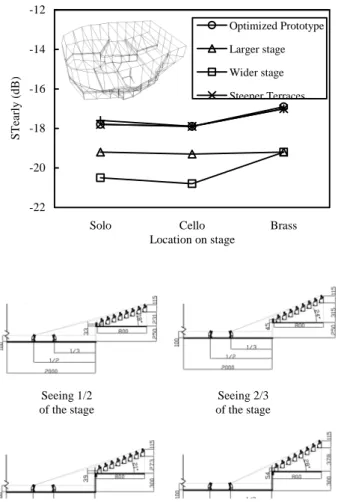
Extended study of computer simulation was performed using an optimized prototype derived from architectural dimensions of 10 halls by Chen [4] [5]. There are 9 sections of seating inside this 21,500 m3 hall where maximum length and width are 44 m and 37 m, respectively. The 22 m wide, 240-m2 stage of the optimized prototype was backed by an 8-m deep terrace. The stage front line was near the geometrical center on plan. The bounding wall of the 1st terrace in front of the stage was 11-m away from the stage front line. The results generally gave the approximate figure of stage support of large vineyard halls when not installed with additional reflec- tors. It shows that limiting the stage size, in particular the width is important. The situation was not improved by in- creasing the slope of the terrace or the height of terraces al- though high side terraces are beneficial for the audience in providing effective early reflections [5].
-22 -20 -18 -16 -14 -12
Solo Cello Brass
Location on stage
STearly (dB)
Optimized Prototype Larger stage Wider stage Steeper Terraces
Figure 2. Simulated STearly (250 Hz through 2 kHz band) as a function of microphone location comparing an optimized
hall derived from architectural dimensions of 10 halls to the halls with varying geometry of the stage.
Figure 3. Sightline analysis of seeing 1/2 of the stage (left) and seeing 2/3 of the stage (right) when the side terrace was set to 2.5 m (top) and 3.0 m (bottom) above the stage floor.
The average distance between the side terraces would be around 20 m if the stage area were kept to 240 m2. When the height difference between the side terrace floor and the stage floor was set to 3 m, the average values of the 10 halls, 540- mm row difference would be required to see 2/3 of the stage.
Higher floor difference would result in steeper terraces unless concession of sightline was made (figure 3).
The influence of width and stage position
One positive side of a vineyard hall is that the musicians at the rear of the stage would perceive softer sound from the powerful percussion and brass sections when there are no nearby surfaces to amply them. This means that a smaller difference in STearly between the brass position and the solo position is expected. Further subjective study would be ex- tremely helpful in better understanding the consequences.
Nevertheless, such a phenomenon may not be fully expressed by STearly because reflections with delays shorter than 20 ms are excluded.
-22 -20 -18 -16 -14 -12
2000 3000 4000 5000 6000 7000 8000 Stage Side Volume (m3)
STearly (dB)
Solo Cello Brass Average
Figure 4. Simulated STearly (250 Hz through 2 kHz band) as a function of microphone location comparing 4 room con-
figurations with varying width and stage position.
Figure 5. Deriving terraced halls (middle left and right) from the 18000 m3, 28 m wide rectangular hall (upper left).
Computer simulation was performed comparing 4 room con- figurations with two widths, 24m vs. 28 m, and two stage positions, directly attached to the back wall vs. with a 6-row terrace behind the stage. The side terrace was set to 3-m above the stage floor and the maximum distance between the terraces were 20 m. The rooms were rectangular with vol- ume set to 18,000 m3. The two configurations with greater stage side volume were the ones with the back terrace. A 200-m2 stage with no riser was used. It was found that ST early only decreased slightly at the solo and the Cello posi-
- 17.0 dB - 17.3 dB
- 16.4 dB - 16.4 dB
- 16.1 dB
Seeing 1/2 Seeing 2/3
of the stage of the stage
23-27 August 2010, Sydney, Australia Proceedings of 20th International Congress on Acoustics, ICA 2010
ISRA 2010 3
tion. STearly at the brass position decreased significantly by adding the back terrace and widening the room.
Means to mitigate the difficulties
As shown in figure 5, the 28-m wide rectangular hall (upper left graph) was used to derive a hall with orthogonal terrace seating (middle left graph). The room width and length was increased to 32 m and 46 m, respectively, by removing the balcony overhangs. This also changed the overall proportion and shape when maintaining the same audience area and room volume.
Two vineyard terrace halls were further developed by intro- ducing a terrace 12-m from the stage front line and 3-m above the stage floor. The side portions of the front terrace were turned diagonally towards the stage. In one hall, the side terraces set back in steps gradually when confronting with the diagonal front terraces (top right graph). Similar layout can be found in Palau de la Musica, Valencia and Auditorior Nacional de Musica, Madrid [6]. In the other hall, both diagonal portions of the front terrace were raised and merged with the side terraces, thus providing a much large reflective surfaces aiming towards the stage (middle right graph). The room height increased slightly because of the raised terraces. STearly values were also shown in figure 5.
By turning balconies into orthogonal terraces as the first step, STearly increased from -17.3 dB to -17.0 dB. The values further increased slightly when introducing a terrace 12-m to the stage. An overhead panel as large as the stage was in- stalled 10-m over the stage in the hall with orthogonal ter- races (bottom right graph). The reflector yielded a STearly of -16.1 dB.
Figure 6. Ray diagrams from a violin position to a brass position (upper) and from a solo position to an audience on
the side terrace (lower).
A comparison was also made between including and exclud- ing the strong reflection from the back terrace wall when calculating STearly for the brass position using the hall with
raised side terraces. STearly dramatically decreased by 1.8 dB when the reflection was excluded.
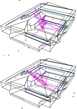
There are other architectural features that can be used to en- hance early energy back to the stage, such as inclined reflec- tors over side terraces used in some vineyard halls and none- vineyard ones. The distance to the stage should be main- tained close enough for the reflectors to be effective. Figure 6 shows ray diagrams for the 32-m hall incorporating various features to enhance early energy on stage. The upper graph demonstrated the effective reflections with 80-ms delay from the overhead panel, the bounding wall of the front terrace, the inclined reflector over the side terrace and the pitched ceiling.
STearly at the solo position was -15.4 dB. This is not ideal, but within operable range [7]. While directing acoustical energy back to the stage, the above mentioned surfaces also played an important role in sending high frequency compo- nents back to the seats on the side and back terraces. The lower graph in figure 6 indicated reflection path through the bounding wall of the front terrace and the splayed, inclined reflectors on the side walls, also arrived with 80-ms delay.
LATE ENERGY
0 1 2
125 250 500 1000 2000 4000
Octave band center frequency (Hz)
EDT (s)
Orthogonal terrace _audience End rectangular_On stage Surrounded rectangular_On stage Orthogonal terrace_On stage
Figure 7. Simulated early decay time as a function of fre- quency comparing the data taken at the audience seats sur- rounding the stage with the data between three source- receiver combinations on stage of three 18000-m3 halls.
Late support (STlate), early decay time measured on stage, and other parameters may all be used to represent subjec- tively perceived reverberant and support of one’s own sound.
Early decay time measured on stage with three source- receiver combinations may be one of the best parameter to represent the perceived reverberant of an orchestra. Early decay time measured on stage can be much shorter than what measured in the audience.
Figure 7 compares simulated early decay time taken at the audience seats surrounding the stage in the hall with orthogo- nal terraces with the data taken on stage of three 18000-m3 halls. The value of on-stage EDT of the hall with end stage was 40 % shorter than the values of the audience. The differ- ence was fairly small when the stage was surrounded, no matter how the geometry of the hall was.
SUMMARIES
1. Controlling the size of stage is essential although stage side wall may not provide effective reflections from or to the sounds from the players near the podium.
2. A surrounded stage provided more uniform early sup- port than an end stage. Subjective study would be help- ful in clarifying the consequence of such a phenomenon.
P2 2
P2 P1
3 P1
29-31 August 2010, Melbourne, Australia Proceedings of the International Symposium on Room Acoustics, ISRA 2010
4 ISRA 2010
Early decay time on a surrounded stage could be as long as the one taken from the audience, indicating more adequate perceived reverberance for the players.
3. By applying a front terrace near the stage, inclined side reflectors, and overhead reflectors, STearly of a moder- ately large terraced concert hall with a back terrace of 6 to 7 rows can be greater than -16 dB.
REFERENCES
1. L, Beranek, “ Concert Hall Acoustics-2008*”, J. AES. 56 (7/8), 532-544, 2008.
2. W. Chiang, C. Huang and Y. Hsu “Acoustical Renova- tion of Tainan Municipal Cultural Center Auditorium”, J.
AES. 51 (10), 933-945, 2003.
3. A. C. Gade, “Investigations of musicians’ room acoustic conditions in concert halls. II. Field experiments and syn- thesis of results,“ Acustica.. 69, 249-261 (1989).
4. Y. Chen: A study on the influence of geometrical charac- teristics to the acoustical performance in vineyard ter- raced concert hall. A Master Thesis of National Taiwan University of Science and Technology (2006).
5. W. Chiang and Y. Chen, “Changing the early reflections in vineyard concert halls” ISRA, Seville (2007).
6. L. Cremer, “Early lateral reflections in some modern concert Halls”. J. Acoust. Soc. Am. 85, 1213-25 (1989).
7. L. L. Beranek, Concert halls and opera houses: How they sound? (Acoust. Soc. Am. New York, 1996).
Proceedings of the International Symposium on Room Acoustics, ISRA 2010 29-31 August 2010, Melbourne, Australia
ISRA 2010 1
A mid-size concert hall with staggered terraced seating
Wei-hwa Chiang (1), Wei Lin (2), I-te Yeh (1) and Yen-kun Hsu (1)
(1) National Taiwan University of Science and Technology 43, Keelung Rd. Section 4, Taipei 106, Taiwan, R.O.C (2) Hwa-Hsia Institute of Technology, 111 Gong Jhuan Rd., Chung Ho, Taipei, Taiwan, R.O.C
PACS: 43.55 FW
ABSTRACT
The new Pingtung Performing Arts Center at Southern Taiwan features a mid-size concert hall. The significant por- tion of seats surrounding the stage and the extra width makes it possible to use terraced seating layout. The terraces were staggered to correspond to the asymmetry of the building and to amplify the size of the reflective surfaces bounding the terraces. Inclined surfaces were also appeared on upper walls where distances between walls were shortened to provide higher order early reflections. Computer simulation was performed to adjust the angle of these diffusive and inclined surfaces to simultaneously satisfy clarity, strength, sectional balance, and stage support. The surfaces near the stage were in particular tuned to direct reflections not only to the nearby audiences at the lowest level but also to the performers and the audiences surrounding the stage.
INTRODUCTION
Terraces and surrounded stage have been introduced in mid- size concert halls recently to increase visual intimacy [1]. The mid-size concert hall is a major facility of the new Pingtung Performing Arts Center at southern Taiwan. Various schemes proposed for the competition phase through the design phases contains simple audience terraces in a rectangular outline.
The seats surrounding the stage that can be alternatives used for choir makes the hall as “semi-surround”. This paper re- ports on the development of design concept.
Figure 1. A sketch (left) and a 3D model (right) of the scheme proposed for the competition phase.
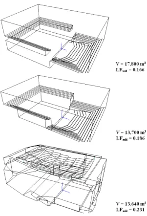
DERIVING THE ROOM FORM Initial approach
An initial scheme was proposed for the competition phase that contains the proportion of the Concertgebouw, Amster- dam. The total area including audience and stage was simi- lar to which required by the program when the under balcony area of the Concertgebouw were removed. The volume was reduced to around 14,000 m3.
Figure 2. Computer simulated 1000-Hz band lateral energy fraction (LF) comparing a simplified Concertge-
bouw (top) to the scheme with removed under balcony seats (middle) and the scheme proposed for the competi-
tion phase (bottom).
29-31 August 2010, Melbourne, Australia Proceedings of the International Symposium on Room Acoustics, ISRA 2010
2 ISRA 2010
Attentions were placed upon:
1. Compensated high frequency components for the seats surrounding the stage. [2]
2. Sufficient strength for the remote seats. [3]
3. Improved lateral energy for the seats in the stall and the seats on side terraces. [3]
An asymmetrical approach was taken when the architect favoured an irregular building form composed with polygon surfaces in varying sizes. The terraces and tilted reflecting panels were staggered that corresponds to the asymmetrical geometry of the foyer spaces and the entire building. This layout amplified the size of the reflective surfaces bounding the terraces and protruded upper walls. Maximum length and width of the hall were 42m and 31 m, respectively. The seat count was around 1,200.
As shown in Figure 1, two major terraces were staggered with a lower, nearer terrace on one side of the hall and a higher, farther terrace on the other side. The splayed terrace bounding walls on the two sides of the main floor not only directed energy laterally to the seats in the stall but also di- agonally back to seats on the two sides of the stage. By set- ting the ceiling in different heights according to the geometry of the terraces, the hall volumes were partially divided that provided stronger and earlier reflections to all audiences.
Computer simulation of the schematic design was compared with the simulation of a simplified Concertgebouw with and without the under balcony area. Overall values of lateral energy fraction boosted (Figure 2).
Development of alternatives
Various alternatives were proposed for the design phase when a different firm, Artect Architects was commissioned for the job. Alternatives were developed that generally fol- lowed the shape outlined by architect. The proportion was slightly narrower and longer when compared with the scheme proposed for the competition phase. The audience floor area was slightly reduced accordingly. One side of the hall was rectangular. The other side consisted with a narrow, splayed front part where the very front of the hall was 25 m. About 3/5 of the rear section was wider with the average width around 28 m.
As shown in figure 3, three major alternatives were analyzed.
The first alternative generally consisted of two staggered terraced where the inner one was on the rectangular side of the room and the outer one on the other side. The second alternative stressed on the reversely splayed wall and terrace bounding wall to counteract the splaying of the front part of the hall. The third alternative emphasized on a raised, long terrace that enlarged the reversely splayed bounding wall.
The alternatives shared some commonalities:
1. The distances between the inner terraces in front of the stage and the center point of the stage front line were controlled between 12 m to 13 m to direct early energy back to the players and to the surrounding seats.
2. An outer loop of terraces was introduced to secure early energy reflected to the inner terraces.
3. Both sides of the rear walls were splayed to compensate for the energy loss due to introducing terraces on the sides that blocked the reflection paths which would exist otherwise in rectangular halls. [4]
4. On the rectangular side of hall there were two levels of audience seating.
Figure 3. Sketches (left) and 3D models (right) of the alternatives proposed for the design phase.
OPTIMIZATION
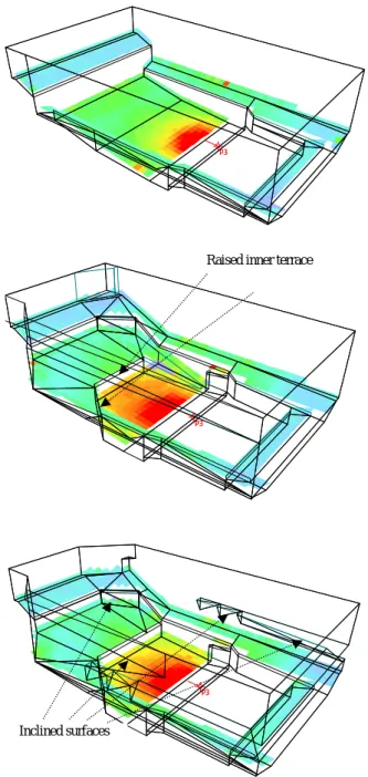
Designing a surrounded concert hall with terrace seating is challenging because the quality of various parts of the audi- ence need to be taken care individually. This requires a thor- ough optimization process. It’s unlike designing a rectangu- lar where the design process can be executed in a statistical manner.
In this project the optimization started with fine tuning the height difference between the inner front terrace and the ter- races surrounding the stage. Taking the development of 2nd alternative as an example, the inner terrace was raised from a original scheme to secure the coverage of 1st order reflections.
However, this should not be overdone; otherwise the upper terraces could be too steep.
When one side of the terrace was turned diagonally, the re- flection paths to the remote seats via the side wall backing the seats would likely be blocked by the turned terrace. It is, therefore, necessary to create other paths to compensate for
23-27 August 2010, Sydney, Australia Proceedings of 20th International Congress on Acoustics, ICA 2010
ISRA 2010 3
the energy loss. This can be realized by splaying and inclin- ing upper parts of the side walls as indicated by Cremer [5].
Incorporating diffused, inclined surfaces above the perimeter seats could also benefit the seats with extra early energy.
Figure 4 shows the distribution of 2-kHz band strength from a voice source comparing a rectangular configuration to pro- gressive changes of alternative 2. The configurations (middle graph) with raised inner terrace showed increased energy for the seats surrounding the stage. Nevertheless, the level of the remote seats near the corner decreased. Incorporating in- clined walls and reflectors attached to the walls (bottom graph) was effective in raising the level throughout the pe- rimeter seats.
Figure 4. Distribution of 2-kHz band strength from a voice source comparing a rectangular configuration (top)
to the configuration (middle) with raised inner terrace and the configuration (bottom) with raised inner terrace
and inclined upper terraces and upper walls.
Figure 5. Simulated 2-k Hz band strength from a voice source as a function of source-receiver distance comparing
the frontal seats (╳) in a rectangular configuration to the surrounding seats in the rectangular configuration (○) and
the optimized configuration with terrace seating (△).
With plane perimeter walls in the rectangular configuration, average 2-kHz strength G surrounding seats was approxi- mately 3dB less than the value of frontal seats with the same source-receiver distance (figure 5). The difference was de- creased approximately to 1.5dB for the optimized configuration with terrace seating. This agreed with the find- ings by Chiang et al using a directional source.
SUMMARY
This research was carried out to analyze acoustical design of a mid size concert hall incooperating staggered terrace seat- ing in a hall with asymmetrical floor plan. Conceptual de- velopment and optimization process were both discussed regarding multi-dimensional criteria based on computer simula- tions. The major findings are:
1. An initial scheme containing the proportion of the Con- certgebouw, Amsterdam was proposed where two major terraces were staggered. Preliminary simulation showed that lateral energy fraction was significantly improved throughout all seats.
2. Alternative schemes were developed following the simi- lar concept but with the room width slightly reduced.
The inner terrace was controlled around 12 m to 13 m away from the stage front line in order to direct early energy back to the players and to the surrounding seats.
An outer loop of terraces was introduced where both sides of the rear walls were splayed. An optimization process was performed to fine tune the height of the ter- races and inclination of walls. Simulations of models progressively changed from a rectangular configuration to an optimized terrace configuration showed that the high frequency strength from a vocal source can be in- creased by around 1.5 dB to improve the perceived tim- bre.
3. The reflection path originally existed in a rectangular form would be blocked by lower terraces on the side, as pointed out by Chen. It is, therefore, necessary to fine tune the reflective surfaces successively from the ones near the stage to the remote, upper surfaces. It is also important to note that adjustment of wall inclining, wall splaying, terrace height should be made with cautions in order maintain good balance among various parameters.
-4 -3 -2 -1 0 1 2 3 4
5 10 15 20 25 30
Source-receiver distance (m) G 2-kHz(dB)
P3 P3
Inclined surfaces
P3 P3
P3 P3
Raised inner terrace
29-31 August 2010, Melbourne, Australia Proceedings of the International Symposium on Room Acoustics, ISRA 2010
4 ISRA 2010
REFERENCES
1. Y. Toyota, K.Oguchi and K. Motoo, “Acoustical design of the new concert hall in Mariinesky Theater, St. Peters- burg”, 19th ICA, Madrid (2007).
2. W. Chiang, W. Lin and Yu, Lin: Optimizating the seats surrounding the platform in a recital hall when consider- ing surrounding source directivity. Applied Acoustics, 69, 1176-1188 (2008).
3. Y. Chen: A study on the influence of geometrical charac- teristics to the acoustical performance in vineyard ter- raced concert hall. A Master Thesis of National Taiwan University of Science and Technology (2006).
4. W. Chiang and Y. Chen, “Changing the early reflections in vineyard concert halls” ISRA, Seville (2007).
5. L. Cremer, “Early lateral reflections in some modern concert Halls”. J. Acoust. Soc. Am. 85, 1213-25 (1989).