國 立 交 通 大 學
材 料 科 學 與 工 程 學 系
博 士 論 文
離子氮化及氣體氮化對鐵鋁錳碳合金顯
微結構、機械性質及抗腐蝕性質影響之
研究
Microstructures, Mechanical Properties and Corrosion Behaviors
of the Plasma-Nitrided and Gas-Nitrided Fe-Al-Mn-C Alloys
研 究 生:陳柏至
指導教授:劉 增 豐 博士
朝 春 光 博士
Microstructures, Mechanical Properties and
Corrosion Behaviors of the Plasma-Nitrided
and Gas-Nitrided Fe-Al-Mn-C Alloys
研 究 生:陳柏至 Student: Po-Chih Chen
指導教授:劉增豐 博士 Advisor: Dr. Tzeng-Feng Liu
朝春光 博士
Dr. Chuen-Guang Chao
國 立 交 通 大 學
材 料 科 學 與 工 程 學 系
博 士 論 文
A Dissertation
Submitted to Department of Materials Science and Engineering College of Engineering
National Chiao Tung University in Partial Fulfillment of the Requirements
for the Degree of Doctor of Philosophy
in
Materials Science and Engineering Sep 2013
Hsinchu, Taiwan, Republic of China
誌 謝
由衷感謝的指導教授劉增豐博士與朝春光教授數年來悉心指導,使學生 能夠順利完成此論文。兩位老師不僅只於學術上的指導,在行為處事上的 教導,也使學生獲益匪淺,銘記在心。口試時承蒙莊振益教授、吳忠春博 士、薄慧雲副所長等口試委員悉心指正,更令學生由衷感謝。 感謝我的父母與家人在這段時間對我的支持與鼓勵,雖然最疼愛我的母 親無法親眼看到我完成學業的這一刻,但我相信她一定已經知道了這個消 息而且會非常欣慰。 感謝實驗室眾多曾經一起共事過的夥伴們給我的幫助,尤其是楊小姐、 志龍學長、凱明學長、世陽學長、浩仰、晟毅、育誠及明翰還有其他眾多 曾經在鐵鋁錳實驗室的同學及在交大認識的朋友,在這裡一併致上最深的 感謝。 最後,僅將論文獻給我最愛的父母親、家人,感謝他們多年來的辛勞、 支持與鼓勵,使我能無後顧之憂地完成學業。 2013/9 於交大離子氮化及氣體氮化對鐵鋁錳碳合金顯微
結構、機械性質及抗腐蝕性質影響之研究
研究生:陳柏至 指 導 教 授 : 劉 增 豐 博 士 朝 春 光 博 士國立交通大學材料科學與工程研究所
中文摘要
本 論 文 主 要 分 別 研 究 離 子 氮 化 及 氣 體 氮 化 對 Fe-8.68wt.%Al-30.5wt.%Mn-1.85wt.%C 和 Fe-9wt.%Al-28wt.%Mn-1.8wt. %C 合金之顯微結構、機械性質與抗腐蝕性質影響。依據實驗的結果,本 論文所得到的具體研究結果如下: (一) Fe-8.68wt.%Al-30.5wt.%Mn-1.85wt.%C 的淬火結構為沃斯田鐵相 (austenite, γ),且在γ基地內有十分緻密奈米級(nano-sized) 的(Fe,Mn)3AlC 碳化物(κ'-碳化物)。緻密奈米級的 κ'-碳化物是合金 在固溶化淬火過程中藉由史賓諾多分解(spinodal decomposition) 相 變 化 在 γ 基 地 內 形 成 。 將 在 淬 火 狀 態 下 的 Fe-8.68wt.%Al-30.5wt.%Mn-1.85wt.%C 合金,經 500C、8 小時離 子氮化處理後,在γ基地內的κ'-碳化物會成長且量變多,而使氮化 後合金能具有優異的強度和延性組合,且在合金表面可得到 40 m厚的氮化層,此氮化層結構由 X 光繞射可知,主要組成為具有面心
立方(Face-Centered Cubic, F.C.C)之 AlN 及少量的 FCC Fe4N;藉
由離子氮化處理後的 Fe-8.68wt.%Al-30.5wt.%Mn-1.85wt.%C 合金 表面氮濃度高達 20wt.% (48 at.%)。所以表面硬度可高達 1860 Hv, 基材硬度為 550 Hv,延伸率為 33.6%,且在 3.5%鹽水中具有極佳抗 腐蝕性質,這些特性都遠優於一般經最佳氮化處理後的高強度合金 鋼,工具鋼,麻田散鐵不銹鋼及析出硬化型不銹鋼。 ( 二 ) Fe-9wt.%Al-28wt.%Mn-1.8wt.%C 的 淬 火 結 構 為 沃 斯 田 鐵 相 (austenite, γ),且在γ基地內有十分緻密奈米級(nano-sized) 的(Fe,Mn)3AlC 碳化物(κ'-碳化物)。緻密奈米級的 κ'-碳化物是合金 在固溶化淬火過程中藉由史賓諾多分解(spinodal decomposition) 相 變 化 在 γ 基 地 內 形 成 。 在 淬 火 狀 態 下 , Fe-9wt.%Al-28wt.%Mn-1.8wt.%C 合 金 經 500C 、 8 小 時 和 50%NH3+50% H2氣氛氣體氮化處理後,表面可得到約 31 m 厚的氮 化層,此氮化層結構由 X 光繞射可知,主要組成為 AlN 及少量的 Fe4N;氣體氮化後表面氮濃度高達 17 wt.% (41 at.%);藉由氣體 氮化處理的 Fe-9wt.%Al-28wt.%Mn-1.8wt.%C 合金,表面硬度可高達 1700 Hv,基材硬度 550 Hv,延伸率為 33.2%,且在 3.5%鹽水中具 有極佳抗腐蝕性質,這些特性都遠優於一般經最佳離子氮化及氣體
氮化處理後的高強度合金鋼,工具鋼,麻田散鐵不銹鋼及析出硬化
型不銹鋼。經由研究發現,氣體氮化試片經拉伸測試後,表面氮化
層與基材間仍有極佳的附著性,不易脫落。此外,藉由氣體氮化後
試片角落無明顯的電弧效應現象產生,而此現象在一般離子氮化處
Microstructures, Mechanical Properties and
Corrosion Resistance of Plasma-Nitrided and
Gas-Nitrided Fe-Al-Mn-C Alloys
Student: Po-Chih Chen Ad v i s o r : D r. T z e n g - F e n g L i u Dr. Chuen-Guang Chao
Department of Materials Science and Engineering
National Chao Tung University
Abstract
The as-quenched Fe-8.68wt.%Al-30.5wt.%Mn-1.85wt.%C alloy was
plasma-nitrided at 500C for 8h with 50% N2 and 50% H2 atmosphereunder a
pressure of 130Pa, and the as-quenched Fe-9wt.%Al-28wt.%Mn-1.8wt.%C
alloy was gas-nitrided at 500C for 8h using an atmosphere of 50% NH3 and
50% H2, respectively. Microstructures, mechanical properties and corrosion
behaviors of the plasma-nitrided Fe-8.68wt.%Al-30.5wt.%Mn-1.85wt.%C and
gas-nitrided Fe-9wt.%Al-28wt.%Mn-1.8wt.%C alloys have been investigated.
On the basis of the experimental examinations, some results can be
[1]. The as-quenched microstructre of the Fe-8.68wt.%Al-30.5wt.%Mn-1.85
wt.%C alloy was austenite (γ) phase containing an extremely high density
of nano-sized (Fe,Mn)3AlC carbides (κ'-carbide). These κ'-carbides were
formed within austenite matrix by spinodal decomposition during
quenching. The size and the amount of the κ'-carbides increased
dramatically when the as-quenched Fe-8.68wt.% Al-30.5wt.% Mn-1.85
wt.% C alloy was plasma-nitrided at 500C for 8h. Consequently, the nitrided alloy could obtain an excellent combination of strength and
ductility after being plasma-nitrided. The nitrided layer obtained is 40
m-thick and composed predominantly of F.C.C AlN with a small amount of Fe4N. Due to the surface nitrogen concentration reached up to 20wt.%
(48at.%), the surface hardness (1860 Hv), substrate hardness (550 Hv),
ductility (33.6%), and corrosion resistance in 3.5% NaCl solution in the
plasma-nitrided Fe-8.68wt.% Al-30.5wt.% Mn-1.85 wt.% C alloy are far
superior to those obtained previously in optimally nitrided high-strength
alloy steels, as well as martensitic and precipitation-hardening stainless
steels.
[2]. The as-quenched microstructre of the Fe-9wt.%Al-28wt.%Mn-1.8wt.%C
nano-sized (Fe,Mn)3AlC carbides (κ'-carbide). These κ' carbides were
formed within austenite matrix by spinodal decomposition during
quenching. The as-quenched Fe-9wt.%Al-28wt.%Mn-1.8wt.% C alloy was
directly gas-nitrided at 500C for 8h with 50%NH3+50% H2 atmosphere,
resulting in a 30 m-thick nitrided layer. The nitrided layer consists predominantly of nano-crystalline AlN with a small amount of Fe4N. The
nitrogen concentration at surface was extremely high up to ~17 wt.% (41 at.%) . Consequently, the surface microhardness (1700Hv), substrate
hardness (550Hv), ductility (33.2%) and corrosion resistance in 3.5% NaCl
solution of the present gas-nitrided Fe-9wt.%Al-28wt.%Mn-1.8wt.% C
alloy are far superior to those obtained previously for the optimally
gas-nitrided or plasma-nitrided high-strength alloy steels, as well as
martensitic and precipitation-hardening stainless steels. Moreover, it is
very novel that the nitrided layer almost remained coherent and adhered
well with the matrix after tensile test. Additionally, the present gas
nitriding appeared to overcome the edge effects commonly encountered in
Contents
page
中文摘要 ……….………i
英文摘要(Abstract) …… ………iv
Contents ………..………vii
List of Tables ………ix
List of Figures ………x
Chapter 1. General Introduction ………..………1
References ………..………9
Chapter 2. A novel high-strength high-ductility and high corrosion-resistance FeAlMnC low-density alloy ………..…16
2-1 Introduction ………..……..……….….…18
2-2 Experimental Procedure ………..…..………..………..…20
2-3 Results and Discussion ……….……..………22
2-4 Conclusions ……….………..………..………30
References ………..………31
Chapter 3. Structure and properties of gas-nitrided nanostructured Fe-9Al-28Mn-1.8C alloy ...………..…….….43
3-2 Experimental Procedure ………..…..………..…………47
3-3 Results and Discussion ……….……..………..…………49
3-4 Conclusions ……….………..………....…………54
References ………..………55
Chapter 4. Summary ………..…67
List of Tables
Table 2.1 Comparisons of polarization test results in 3.5% NaCl solution and
hardness of the plasma nitrided Fe-8.68wt.%Al-30.5wt.%Mn-1.85
wt.%C alloy and the optimally plasma nitrided alloy steels as well
List of Figures
Figure 1.1 (a) L'12 crystal structure. (b) L12 crystal structure ...…….13
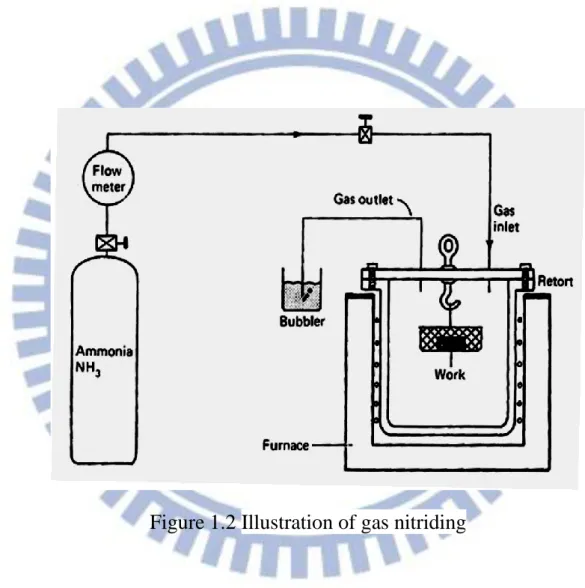
Figure 1.2 Illustration of gas nitriding………...….14
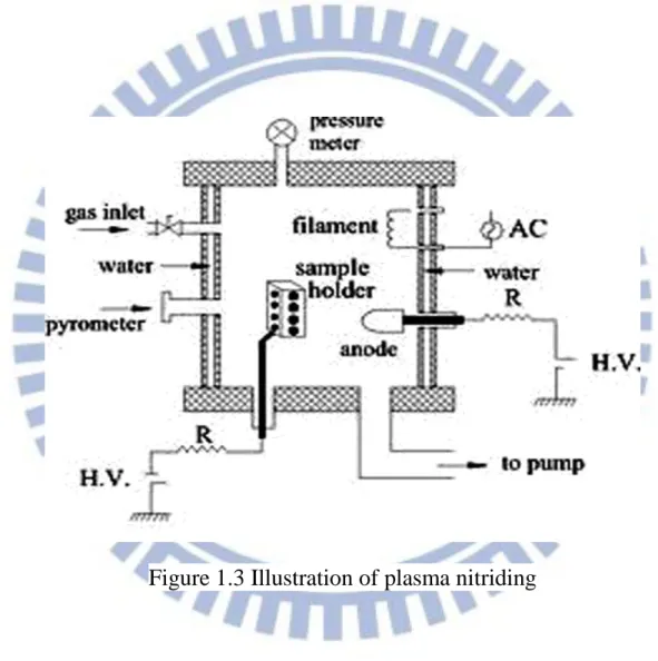
Figure 1.3 Illustration of plasma nitriding………..15
Figure 2.1 (a)TEM (100)κ′ dark-field (DF)image of the as-quenched alloy. (b)
~ (d)The selected area diffraction patterns (SADPs) taken from the
as-quenched alloy (hkl:γ, hkl: κ′-carbide). The zone axis is [001],
[011] and [111], respectively. (e) SEM image of the present
nitrided alloy (etched in 5% nital). (f) X-ray diffraction pattern for
the present nitrided alloy……….…………...30
Figure 2.2 (a)Nitrogen concentration profile measured by GDS of the present
nitrided alloy. (b)Hardness profile of the present nitrided alloy. (c)
SEM image of the present nitrided alloy after tensile test……..….34
Figure 2.3 (a)Polarization curves for the present untreated and nitrided alloys
in 3.5% NaCl solution. (b)-(c) SEM images of the corroded surfaces
for the present untreated and nitrided alloys, respectively……..…36
Figure 3.1 (a) SEM cross-sectional image of the gas-nitrided alloy. Inset image
shows the enlarged microstructure near the interface. (b) ~ (e) The
elemental mapping images taken from the rectangular region
marked in (a) for Al、 N、Mn and Fe, respectively. (f) XRD results
for as-quenched and nitrided alloys……...…...………….53
Figure 3.2 (a)Nitrogen concentration profile of the present gas-nitrided alloy.
(b) Hardness profile of the present gas-nitrided alloy. (c)
Polarization curve for the present gas-nitrided alloy in 3.5% NaCl
solution. (d) SEM surface image of the gas-nitrided alloy……….57
Figure 3.3 (a) SEM image of the free surface of the gas-nitrided alloy after
tensile test. (b) AFM image of one of the fractured fragment. (c)
SEM image of the fractured surface taken by slightly tilting the
sample ...59
Chapter 1.
General introduction
Phase transformations, mechanical properties and corrosion resistance in fully
austenitic Fe-(4.9~11)Al-(28~35)Mn-(0.5~1.3)C alloys have been extensively
studied by many workers [1-40]. In the Fe-Al-Mn-C alloy systems, manganese
and carbon can enhance the stability of the austenitic structure which has a
better workability and ductility. Aluminum is a ferrite stabilizer and plays an
important role on the formation of (Fe,Mn)3AlC carbides (κ′-carbides). An
increase in the aluminum content will be beneficial to the mechanical strength of
the alloys. In general, the F.C.C. structure can be stabilized by increasing the
contents of the manganese and carbon, or decreasing the content of the
aluminum. It is well-known that through a proper combination of aluminum,
manganese and carbon, an alloy with a fully austenitic structure can be achieved.
In previous works, it is clearly demonstrated that the as-quenched
microstructure of the FeAlMnC alloys with a chemical composition in the range
of Fe-(6-11)wt.%Al-(26-34)wt.%Mn-(0.54-1.3)wt.%C was single-phase
austenite (γ). When the as-quenched alloys were aged at 500~750℃ for
moderate times, fine and coarse (Fe,Mn)3AlC carbides having an L′12-type
structure could be observed to precipitate coherently within the γ matrix and
heterogeneously on the γ/γ grain boundaries, respectively. For convenience, the
coherently within the γ matrix and heterogeneously on the γ/γ grain boundaries
[8]. In the previous studies, it was seen that the κ carbide has an L12-type
structure [37-40]. However, Sarreal and Koach suggested that the κ-carbide
has an L12 or L'12 structure [37]. The only difference between the L12 and L'12
structure is the degree of order of the carbon atom arrangement. The carbon
atoms are randomly situated on octahedral site for the L12 structure, while they
are all located in the body-centered, octahedral site for the L'12 structure, as
shown in Figure 1.1. Based on these previous studies, it can be generally
concluded that due to the formation of the fine k′ carbides within the γ matrix
and absence of precipitates on the grain boundaries, the alloys could possess an
optimal combination of strength and ductility when the as-quenched alloys were
aged at 550℃ for about 16 h [8-10, 14]. With an elongation better than about
30%, the values of UTS and YS could be attained to be 1130-1250 MPa,
1080-1120 MPa and 33-31%, respectively [8-10, 14-15].
Recently, in order to further improve the strength, small amounts of V, Nb,
Mo and W were added to the austenitic FeAlMnC (C ≦ 1.3 wt.%) alloys [9-10,
14]. After solution heat-treatment or controlled-rolling followed by an optimum
aging at 550℃ for 15~16h, the UTS and YS of the FeAlMnMC (M=V, Nb, Mo,
W) alloys were significantly increased up to 1130-1220 and 890-1080 MPa,
In our previous studies, we investigated the as-quenched microstructure of the
Fe-9.8 wt.% Al -29 wt.% Mn-(1.45-2.05) wt.% C alloys, and found that an
extremely high density of nano-sized κ′-carbides was formed within the γ matrix
by spinodal decomposition during quenching [41]. This is quite different from
that observed in the austenitic Fe-Al-Mn-C (C ≦ 1.3 wt. %) alloys, in which
fine κ′-carbides could only be observed in the aged alloys. The UTS, YS and
elongation of the as-quenched FeMnAlC alloys with 1.8≦C≦2.0 wt. % were
1080~1105 MPa, 868~883 MPa and 55.5~54.5 %, respectively [41-42].
Furthermore, after being aged at 450~550 oC for moderate times, the alloys could possess ultrahigh UTS ranging from 1395 to 1552 MPa and YS ranging
from 1262 to 1423 MPa with a good elongation ranging from 32.5 to 25.8 %
[41-42].
Although the austenitic FeMnAlMC alloys could possess excellent combination of strength and ductility, the corrosion behavior of the alloys in
aqueous environments was not adequate for applications in aggressive
environment [48-52]. In order to improve the corrosion resistance, Cr was added
to the austenitic FeMnAlC alloys [51-54]. Consequently, it was found that the
corrosion potential (Ecorr) and pitting potential (Epp) of as-quenched austenitic
Fe-(29.2-31.3)wt.%Mn-(7.1-9.1)wt.%Al-(2.8-6)wt.%Cr-(0.88-1.0)wt.%C alloys
mV, respectively [51-54]. The results were much better than the Ecorr
(-920~-789 mV) and Epp (-500~-280 mV) of the austenitic as-quenched
FeMnAlC alloys [48-52].
FeMnAlC alloys could improve the corrosion resistance and maintain almost
the same mechanical properties when Cr was added in FeAlMnC alloys,
however, it was not a cost-effective method. Recently, nitriding was widely
utilized to improve surface hardness and corrosion resistance of metallic
materials. However, high strength alloy steels, martensitic as well as
precipitation hardening stainless steels were needed to temper at 15 oC above the nitriding temperature prior to nitriding. These high strength alloy steels and
stainless steels couldn’t obtain remarkable combination of strength and ductility,
as well as corrosion resistance, with the one-step treatment. It is worthwhile to
explore how the corrosion behaviors and mechanical properties of the FeAlMnC
alloys could be simultaneously optimized by one-step nitriding scheme for
applications in aggressive environments.
Nitriding is a heat-treatment process that nitrogen diffuses into the surface of
a metallic material to create a hardened surface and enhance wear resistance. It
is predominantly used on alloy steels and austenitic, martensitic as well as
precipitation-hardening stainless steels. The most two common methods used
described as follows.
In gas nitriding the donor is a nitrogen rich gas, usually ammonia (NH3),
which is why it is sometimes known as ammonia nitriding.[57] When ammonia
comes into contact with the heated work piece, it disassociates into nitrogen and
hydrogen. The nitrogen then diffuses into the surface of the material creating a
nitrided layer. The detailed gas nitriding process is shown in Figure 1.2.
Traditionally, gas nitriding has been used in improving wear resistance and
endurance characteristics in metallic materials. The properties of a nitrided steel
are determined by both the core strength and the structural characteristics of the
compound layer and the diffusion zone. Recent developments have led to a
process that can be accurately controlled. The thickness and phase constitution
of the resulting nitrided layers can be selected and the process optimized for the
particular properties required.
The gas nitriding method has advantages such as relatively low equipment
cost - especially compared with plasma nitriding and all round nitriding effect.
Plasma nitriding, also known as ion nitriding, glow-discharge nitriding or plasma ion nitriding, is an industrial surface hardening treatment for metallic
materials and steels. In plasma nitriding, the reactivity of the nitriding media is
not due to the temperature but to the gas ionized state. In this technique intense
surface to be nitrided. Such highly active gas with ionized molecules is
called plasma, naming the technique. The gas used for plasma nitriding is
usually pure nitrogen. The plasma nitriding procedure is shown in Figure 1.3.
Plasma nitriding can improve the surface hardness and wear resistance of
various engineering materials, as gas nitriding. In practice, there is increasing
interest by industry in plasma based nitriding technologies which offer many
advantages over traditional gas nitriding, particularly, in terms of reduced gas
consumption, reduced energy consumption and the completely removal of any
environmental hazard. Plasma nitriding advantage is related to that not only the
performance of metal parts gets enhanced but working lifespan gets boosted.
Furthermore, the hardness of the surface during plasma nitriding treatment is
higher than gas nitriding due to higher N concentration. Plasma nitriding can
thus be performed in a broad temperature range, from 260°C to more than
600°C. However, in conventional plasma nitriding process, the treated
components are submitted to high cathodic potentials and the plasma acts
directly in surface of the components. This brings some inherent shortcoming
for plasma nitriding, such as damage caused to parts by arcing, the “edging
effect”, and difficulty in maintaining a uniform component temperature,
particularly in full workloads of components with varied dimensions and
Therefore, the purpose of the present work is to investigate the
microstructures, mechanical properties and corrosion behaviors of
plasma-nitrided and gas-nitrided FeAlMnC alloys by using optical microscope
(OM), scanning electron microscopy (SEM), transmission electron microscopy
(TEM), X-ray, Glow Discharge Spectrometer (GDS) and Vicker’s indenter,
Potentiostat / Galvanostat and energy dispersive X-ray spectrometer (EDS)
analyses. Tensile tests were carried out at room temperature with an Instron
8501 tensile testing machine at a strain rate of 6.710-4 s-1. The detailed experiment results are presented in Chapters 2 and 3, recpectively.
References
[1] K. Sato, K. Tagawa, Y. Inoue, Scripta Metall. 22 (1988) 899.
[2] T.F. Liu, J.S. Chou, C.C. Wu, Metal. Trans. A 21 (1990) 1891.
[3] K.H. Han, J.C. Yoon, W.K. Choo, Scripta Metall. 20 (1986) 33.
[4] C.N. Hwang, T.F. Liu, Scripta Mater. 36 (1997) 853.
[5] C.Y. Chao, C.N. Hwang, T.F. Liu, Scripta Metall. 28 (1993) 109.
[6] K. Sato, K. Tagawa, Y. Inoue, Metal. Trans. A 21 (1990) 5.
[7] C.N. Hwang, C.Y. Chao, T.F. Liu, Scripta Metall. 28 (1993) 263.
[8] W.K. Choo, J.H. Kim, J.C. Yoon, Acta Mater. 45 (1997) 4877.
[9] I.S. Kalashnikov, O. Acselrad, A. Shalkevich, J. Mater. Process. Technol.
136 (2003) 72.
[10] G.S. Krivonogov, M.F. Alekseyenko and G.G. Solovyeva, Fiz. Metal.
Metalloved 39 (1975) 775.
[11] S.C. Tjong, S.M. Zhu, Mater. Trans. 38 (1997) 112.
[12] I.S. Kalashnikov, O. Aksel’rad, M.S. Khadyev, Metal Sci. Heat Treat. 48
(2006) 5.
[13] Kalashnikov, O. Acselrad, A. Shalkevich, L.C. Pereira, J. Mater. Eng.
Perform. 9 (2000) 597.
[14] I.S. Kalashnikov, B.S. Ermakov, O. Aksel’rad, L.K. Pereira, Metal Sci. Heat
[15] Y. Kimura, K. Handa, K. Hayashi, Y. Mishima, Intermetallics 12 (2004)
607.
[16] S.K. Banerji, Met. Prog. Apr (1978) 59.
[17] H.W. Leavenworth, Jr. and J.C. Benz, J. Met. vol. 37, (1985) 36.
[18] J. Charles, A. Berghezan, A. Lutts, P.L. Dancoisne, Met. Prog. 120 (1981)
71.
[19] R. Wang, F.H. Beck, Met. Prog. 123 (1983) 72.
[20] J.C. Garcia, N. Rosas, R.J. Rioja, Met. Prog. 124 (1982) 47.
[21] D.J. Schmatz, Trans. ASM. 52 (1960) 898.
[22] M.F. Alekseyenko, G.S. Krivonogov, L.G. Kozyreva, I.M. Kachanova, L.V.
Arapova, Met. Sci. Heat Treat. 14 No.3-4 (1972) 187.
[23] L.I. Lysak, M.F. Alekseyenko, A.G. Drachinskaya, N.A. Storchak, G.S.
Krivonogov, Metallofizika 59 No.4 (1975) 29.
[24] R.E. Cairns, Jr. and J.L. Ham, U.S. patent, No. 3111405 (1963).
[25] I. Briggs, G.J. Russell, A.G. Clegg, J. Mater. Sci. 20 (1985) 668.
[26] W.K. Choo, K.H. Han, Metall. Trans. A 16 (1985) 5.
[27] W.K. Choo, D.G. Kim, Metall. Trans. A 18 (1987) 759.
[28] S.C. Tjong, N.G. Ho, Metallography 21 (1988) 199.
[29] G.L. Kayak, Met. Sci. Heat Treat. 22 No.2 (1969)95.
[31] I.S. Kalashnikov, O. Acselrad, L.C. Pereira, T. Kalichak, M.S. Khadyyev, J.
Mater. Eng. Perform. 9 (2000)334.
[32] S.C. Tjong, C.S. Wu, Mater. Sci. Eng. 80 (1986) 203.
[33] I.F. Tsu, T.P. Perng, Metall. Trans. A 22 (1991) 215.
[34] S.M. Zhu, S.C. Tjong, Scripta 36 (1997) 317.
[35] K. Ishida, H. Othani, N. Statoh, R. Kainuma, T. Nishizawa, ISIJ
International 30 (1990) 680.
[36] C.S. Wang, C.N. Hwang, C.G. Chao, T.F. Liu, Scripta Mater. 57 (2007) 809.
[37] J.A. Sarreal, C.C. Koch, Mater. Sci. Eng. A 136 (1991) 141.
[38] J.E. Krzanowski, Metall. Trans. A 19 (1988) 1873.
[39] P.J. James, J. Iron Steel Inst. (1969) 54.
[40] K. Sato, K. Tagawa, Y. Inoue, Mater. Sci. Eng. A 111 (1989) 45.
[41] K.M. Chang, C.G. Chao, T.F. Liu, Scripta Mater. 63 (2010) 162.
[42] C.L. Lin, C.G. Chao, H.Y. Bor, T.F. Liu, Mater. Trans. 51 No.6 (2010) 1084.
[43] S.C. Tjong, N.J. Ho, Metallography 21 (1988) 1996.
[44] T.F. Liu, C.M. Wan, Strength Met. Alloys 1 (1986) 423.
[45] C.C. Wu, J.S. Chou, T.F. Liu, Metall. Trans. A 22A (1991) 2265.
[46] K.S. Chan, L.H. Chen, T.S. Lui, Mater. Trans. 38 No.5 (1997) 420.
[47] S.C. Chang, Y.H. Hsiau, M.T. Jahn, J. Mater. Sci. 24 (1989) 1117.
[49] W.T. Tsai, J.B. Duh, J.T. Lee, J. Mater. Sci. 22 (1987) 3517.
[50] J.B. Duh, W.T. Tsai, J.T. Lee, Corrosion Nov. (1988) 810.
[51] S.C. Chang, J.Y. Liu, H.K. Juang, Corrosion 51 No.5 (1995) 399.
[52] C.J. Wang, Y.C. Chang, Mater. Chem. Phys. 76 (2002) 151.
[53] C.S. Wang, C.Y. Tsai, C.G. Chao, T.F. Liu, Mater. Trans. 48 (2007) 2973.
[54] Y.H. Tuan, C.S. Wang, C.Y. Tsai, C.G. Chao, T.F. Liu, Mater. Chem. Phys.
114 (2009) 595.
[55] S.C. Chang, W.H. Weng, H.C. Chen, S.J. Lin, P.C.K. Chung, Wear 181-183
(1995) 511.
[56] S.T. Shih, C.Y. Tai, T.P. Perng, Corrosion Feb (1993) 130.
Figure 1.1(a)
Figure 1.1(b)
Chapter 2.
A novel high-strength high-ductility and
high corrosion-resistance FeAlMnC
A novel high-strength high-ductility and high corrosion-resistance
FeAlMnC low-density alloy
Abstract
The as-quenched Fe-8.68 wt.% Al-30.5 wt.% Mn-1.85 wt.% C alloy is plasma
nitrided at 500C for 8h. The nitrided layer obtained is 40 m-thick and composed predominantly of AlN with a small amount of Fe4N. The resultant
surface hardness (1860 Hv), substrate hardness (550 Hv), ductility (33.6%), and
corrosion resistance in 3.5% NaCl solution in the present nitrided alloy are far
superior to those obtained previously in optimally nitrided high-strength alloy
2-1 Introduction
In view of excellent combinations of high-strength and high-ductility as well
as without needing expensive strategic alloying elements (e.g. Cr, Ni, Mo), the
austenitic Fe-Al-Mn-C quarternary alloys have been attracting tremendous
attention. Moreover, due to high aluminum content, the density of the alloys is
about 13% lower than conventional steels [1]. Previous studies showed that the
as-quenched microstructure of Fe-(7.8-10) wt.% Al-(28-30) wt.% Mn-(0.8-1.3)
wt.% C alloys was single-phase austenite (γ) [1-5]. An optimal combination of
strength and ductility could be obtained for the Fe-Al-Mn-C alloys aged at
550oC for about 16h [2, 3]. Under these aging conditions, a high density of fine (Fe,Mn)3AlC carbides (κ′-carbides) having L′12 (ordered FCC) structure
precipitated coherently within γ matrix without any grain boundary precipitates.
After optimal aging, the ultimate tensile strength (UTS), yield strength (YS) and
elongation (El) of the Fe-Al-Mn-C alloys could reach 1130-1250 MPa,
1080-1120 MPa and 33-31%, respectively [2,3].
Recently, we investigated the as-quenched microstructure of the Fe-9.8 wt.%
Al -29 wt.% Mn-(1.45-2.05) wt.% C alloys, and found that an extremely high
density of nano-sized κ′-carbides was formed within γ matrix by spinodal
decomposition during quenching [6]. This is quite different from that observed
could only be observed in aged alloys. Due to the pre-existing nano-sized
κ′-carbides, the aging temperature and time required to attain the optimal
combination of strength and ductility are, respectively, much lower and less than
those of the previous Fe-Al-Mn-C (C≦1.3 wt.%) alloys. For example, with
almost equivalent elongation, the Fe-9 wt. % Al -28 wt.% Mn-1.8 wt.% C alloy
aged at 450C for 12h can possess yield strength about 28% higher than that of the optimally aged Fe-Al-Mn-C (C≦1.3 wt.% ) alloys [7].
Although the austenitic Fe-Al-Mn-C alloys could possess excellent
combination of strength and ductility, the corrosion resistance of the alloys was
insufficient for applications in aggressive environments [4,5]. Plasma nitriding
was widely utilized to improve surface hardness and corrosion resistance of
metallic materials [8-19]. However, to date, little information concerning the
plasma nitriding treatment for Fe-Al-Mn-C alloys has been reported in the
literature. The main purpose of this work is to investigate the characteristics of
an Fe-8.68 wt.% Al-30.5 wt.% Mn-1.85 wt.% C alloy after plasma nitriding at
2-2 Experimental Procedure
The Fe-8.68 wt. % Al -30.5 wt.% Mn-1.85 wt.% C alloy was prepared in an
air induction furnace. After being homogenized at 1150oC for 6h, the ingot was hot-rolled to a 6-mm-thick plate. The plate was subsequently solution
heat-treated at 1200oC for 2h and then quenched into room-temperature water. The specimen was polished using SiC papers to 2400 grit before plasma
nitriding. The plasma nitriding process was performed at 500oC for 8h using an atmosphere of 50% N2 and 50% H2 under a pressure of 130Pa. Scanning electron
microscopy (SEM) was used to investigate the surface and cross-sectional
morphologies of the nitrided alloy by using JEOL 6500 with 15kv voltage.
Transmission electron microscopy examination was performed on a JEOL
JEM-2100 transmission electron microscope (TEM) operating at 200kv. TEM
specimens were prepared by means of a double-jet electropolisher with an
electrolyte of 60% acetic acid, 30% ethanol and 10% perchloric acid. The
polishing temperature was kept in the range from -30 oC to -15 oC, and the current density was kept in the range from 3x10⁻⁴ to 4x10⁻⁴ A/m2. X-ray diffraction (XRD) was carried out using a Bruker D8 with Cu-Kα radiation. The
nitrogen concentration and microhardness of the nitrided alloy were determined
respectively. Potentiodynamic polarization curves were measured in 3.5% NaCl
solution at 25oC. Electrochemical polarization curves were obtained by using an EG&G Princeton Applied Research Model 273 galvanostat / potentiostat.
Speciemens with an exposed surface area of ~1cm2 were ground with 2400 grit SiC paper and then with 1.5m Al2O3 powder, washed in distilled water and
rinsed in acetone prior to passivation. Poteniodynamic polarization curves were
obtained at a potential scan rate of 2 mV/s from -1 V to 3V. A saturated calomel
electrode (SCE) and a platinum wire were used as reference and auxiliary
electrodes, respectively. The specimens for tensile tests were prepared according
to ASTM standards. The gauge length, width and thickness of the tensile test
specimens are 50 mm, 12.5 mm and 6 mm, respectively. Tensile tests were
carried out at room temperature with an Instron 8501 tensile testing machine at a
2-3 Results and Discussion
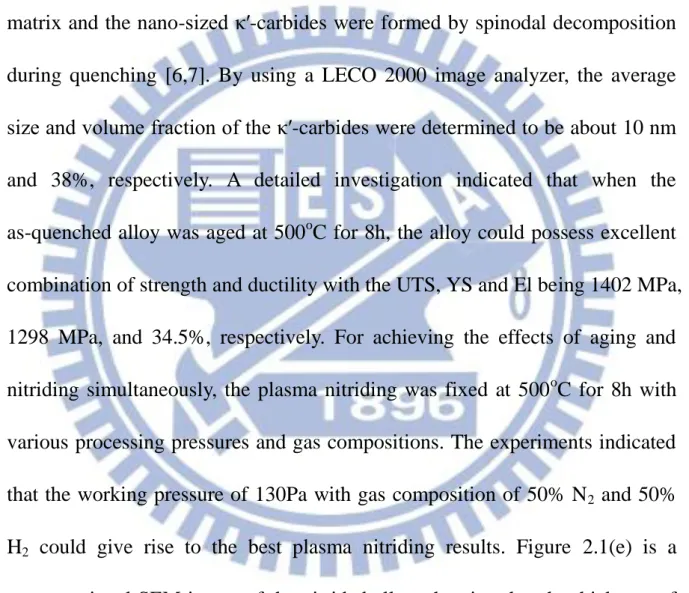
Figure 2.1(a) is a TEM (100)κ′ dark-field image and Figure 2.1(b)~(d) are the
corresponding diffraction patterns of the as-quenched alloy, revealing that an
extremely high density of nano-sized κ′-carbides can be observed within γ
matrix and the nano-sized κ′-carbides were formed by spinodal decomposition
during quenching [6,7]. By using a LECO 2000 image analyzer, the average
size and volume fraction of the κ′-carbides were determined to be about 10 nm
and 38%, respectively. A detailed investigation indicated that when the
as-quenched alloy was aged at 500oC for 8h, the alloy could possess excellent combination of strength and ductility with the UTS, YS and El being 1402 MPa,
1298 MPa, and 34.5%, respectively. For achieving the effects of aging and
nitriding simultaneously, the plasma nitriding was fixed at 500oC for 8h with various processing pressures and gas compositions. The experiments indicated
that the working pressure of 130Pa with gas composition of 50% N2 and 50%
H2 could give rise to the best plasma nitriding results. Figure 2.1(e) is a
cross-sectional SEM image of the nitrided alloy, showing that the thickness of
the nitrided layer is about 40 μm. The grain boundaries of the substrate are
clearly revealed by the nital etchant, while the nitrided layer remains intact.
Moreover, the boundary between nitrided layer and substrate is obscure. Figure
diffraction peaks, diffraction peaks belonging to AlN and Fe4N can also be
detected. Both AlN and Fe4N have FCC structure with lattice parameters of
4.06 nm and 3.79 nm, respectively [20,21]. Moreover, the intensity of the AlN
diffraction peaks is much higher than that of Fe4N phase, indicating that the
nitrided layer is composed predominantly of AlN phase with significantly less
amount of Fe4N phase. Furthermore, the XRD peaks are fairly broadened,
which may be due to the large amount of nitrogen incorporated in these phases
[11-12, 15-19]. Figure 2.2(a) shows the nitrogen concentration as a function of
depth, revealing that at the outmost surface, the nitrogen concentration is as
high as about 20 wt.% (48 at.%). The nitrogen concentration gradually
decreases with increasing depth. Figure 2.2(b) shows the microhardness of the
nitrided alloy as a function of depth. The surface microhardness is extremely
high (1860 Hv), and gradually decreases with increasing depth until the
substrate value of about 550 Hv. Tensile test indicated that UTS, YS, and El of
the nitrided alloy were 1388 MPa, 1286 MPa, and 33.6%, respectively, which
are comparable to those obtained for the same alloy aged at 500oC for 8h. By slightly tilting the specimen, the fracture and free surfaces could be observed
simultaneously, as illustrated in Figure 2.2(c). High density of dimples can be
seen within the austenite + κ′-carbides matrix, and no microvoids or
and substrate. Obviously, the substrate remains ductile and the nitrided layer
itself is very compact with good adhesion to the substrate.
Potentiodynamic polarization curves for as-quenched and plasma nitrided
alloys in 3.5% NaCl solution are shown in Figure 2.3(a). Evidently, for the
untreated alloy (curve I), there is no apparent passivation region. The corrosion
current density (icorr) and corrosion potential (Ecorr) are 2×10
-6
A/cm2 and -790 mV, respectively. However, an obvious passivation region can be observed for
the nitrided alloy (curve II), and icorr is evidently reduced by about three orders
of magnitude to 6×10⁻¹⁰ A/cm2 and Ecorr is drastically improved to +50 mV.
Moreover, the values of the pitting corrosion current density (ip) and pitting
potential (Epit) for the nitrided alloy are 2×10 -7
A/cm2 and +2030 mV, respectively. Apparently, plasma nitriding has resulted in a pronounced
enhancement in corrosion resistance. Figures 2.3(b) and 2.3(c) are SEM images
of the corroded surfaces, indicating that during polarization the grain
boundaries and matrix of the untreated alloy were severely attacked, while only a few very small (0.3 m) corrosion pits (as indicated with arrows in Figure 2.3(c)) were formed for the nitrided alloy.
That the nitrided layer of the present nitrided alloy is composed
predominantly AlN with a small amount of Fe4N is a remarkable feature. For
high corrosion resistance, the nitrided low-Cr (Cr<1.2 wt.%) alloy steels (e.g.
AISI 4140, 4340 and 5140) and high-Cr (Cr>12 wt.%) martensitic stainless
steels (e.g. AISI 410) as well as precipitation-hardening (PH) stainless
steels( e.g. AISI 17-4PH) were widely used. According to extensive previous
studies, the optimal nitriding conditions for the low-Cr steels were 520-550 oC for 4-6h [8-10], while those for high-Cr stainless steels were 400-480 oC for 2-20h [11-19]. The nitrided layer formed in these body-centered cubic (BCC)
steels is mainly composed of Fe3N (HCP) and Fe4N (FCC), without or with a
trace of CrN (FCC) [8-19]. After optimal nitriding treatment, the surface
microhardness of the low-Cr alloy steels and high-Cr stainless steels were
between 890-940 Hv and 1000-1350 Hv, respectively, which are far lower than
1860 Hv obtained in the present nitrided alloy. The primary reason is that due
to AlN formation in the present nitrided alloy, nitrogen concentration near the
surface can reach 20 wt.%; whereas the surface nitrogen concentrations of the
optimally nitrided low-Cr alloy steels and high-Cr stainless steels were 5.7-10
wt.% and 10-15 wt.%, respectively [17,22-25]. The hardness of the nitrides
generally increases with increasing nitrogen concentration. For instance, the
hardness of AlN is 25.7GPa [26], which is much higher than that of Fe3N
(11.2-12.4 GPa), and Fe4N (8.6-11.2 GPa) [22, 27]. It is worthwhile to
alloy is also much higher than 210-400 Hv obtained in the optimally nitrided
high-strength alloy steels and stainless steels [9-16, 18]. The reason is that prior
to nitriding, these steels need to temper at 15C above the nitriding temperature [28], and then nitrided at the optimal temperature for a long duration. This
would deteriorate the substrate hardness drastically [23]. Detailed comparisons
of surface hardness and substrate hardness are listed in Table 1.
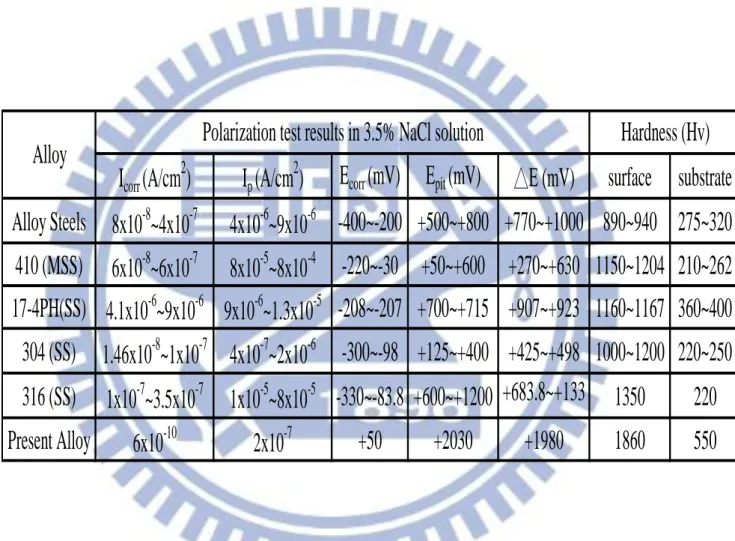
The most important indicators for evaluating the corrosion resistance of
metallic materials are icorr, ip, Ecorr, and Epit; lower current densities and higher
potentials indicate better corrosion resistance [8-19]. Table 1 lists the values of
icorr, ip, Ecorr, and Epit obtained using the same SCE in 3.5% NaCl solution at
room-temperature for the present nitrided alloy, and the previous results for the
optimally nitrided low-Cr alloy steels (including 4140, 4340, and 5140),
high-Cr 410 martensitic stainless steels, 17-4 precipitation hardening steels
(17-4PH) and austenitic stainless steels (including AISI 304, 316). In Table 1, it
is obvious that the corrosion resistance of the present nitrided alloy is far
superior to that of the low-Cr alloy steels and high-Cr stainless steels. The
reasons are described in detail as follows. It is indicated that the low-Cr alloy
steels have the lowest surface and substrate hardness. The reason is that prior to
nitriding, these steels need to temper at 15C above the nitriding temperature, and then nitrided at the optimal temperature for a long duration. This would
deteriorate the substrate hardness drastically. Moreover, it has shown that
plasma nitriding is effective in improving the tribological properties and
surface hardness of 410 and 420 martensitic stainless steels under various
testing conditions [11-12]. It is also indicated that when nitriding is carried out
below a temperature at which CrN forms, the nitrided layer retains its
martensite structure but with a larger lattice parameter than the bulk, so that
“expanded martensite” has been proposed in comparison to “expanded
austenite”. For this reason, surface hardness of the optimally nitrided
martensite stainless steels is slightly lower than that of austenitic stainless steels.
Additionally, 17-4PH stainless steels have been widely utilized in industries.
However, nitrided 17-4PH stainless steel has low surface hardness and poor
tribological properties, which could limit its applications in such areas where
contact and wear are involved. Some surface modification methods have been
carried out for improving the properties of this kind of steel. Recently, plasma
nitriding treatments on 17-4PH steel at lower temperature have been developed.
It indicates that these treatments can provide a considerable improvement in the
wear resistance of the precipitation-hardening stainless steels without
significantly compromising its desirable corrosion-resistant properties.
Consequently, 17-4PH steel also has the excellent combination of surface
stainless steels have the highest surface hardness than other low-Cr and high-Cr
steels. It has been explained that when nitriding temperature is sufficiently low,
a nitrogen expanded austenite (namely S-phase) can be produced on the surface
of the austenite stainless steel. Due to contain a significant amount of nitrogen
in the S-phase, the low temperature nitrided austenitic stainless steels can
possess not only considerably increased surface hardness and wear resistance,
but also much improved corrosion resistance. For example, when nitriding at a
temperature around or below 500oC can produce a thick nitrided case on the austenitic stainless steels surface, which indeed largely improve the surface
hardness and wear resistance [15-19]. However, corrosion resistance of the
austenitic stainless steels is dramatically reduced after nitriding at higher
temperature due to the formation of chromium nitride and the depletion of free
chromium in the austenite matrix. Consequently, the higher temperature
nitrided stainless steel is thus no longer stainless.
Evidently, under the same testing conditions, the icorr and ip of the present
alloy are two or three orders of magnitude lower, while the values of Ecorr and
Epit are significantly higher than those of the alloy steels and stainless steels,
indicating that the present nitrided alloy has far superior corrosion resistance in
3.5 % NaCl solution. Moreover, the size of the surface corrosion pits of the
smaller than that (10-200 m) observed in optimally nitrided alloy steels and stainless steels under similar polarization tests [8-9,12-14]. The lower ip value
results in smaller corrosion pits [12, 14], which is in good agreement with the
experimental results shown in Table 1. Another important criterion for
evaluating the pitting resistance is the difference between Epit and Ecorr, namely
△ E=EpitEcorr [29]. In Table 1, the △ E value for optimally nitrided alloy steels
and stainless steels is between +270 ~ +1330 mV, while that for the present
nitrided alloy is +1980 mV, which again demonstrates the superior
characteristics of the present nitrided alloy, presumably due to the high nitrogen
concentration at surface [17].
Another feature of the present study is that after etching the boundary
between nitrided layer and substrate was obscure (Figure 2.1(e)) and no
microvoids or cracks could be detected between nitrided layer and substrate of
the fractured surface (Figure 2.2(c)). This is attributed to the fact that both AlN
and Fe4N phases have the same FCC crystal structure as the matrix and
-carbides with very similar lattice parameters, which may result in excellent adhesion between nitrided layer and substrate.
2-4 Conclusions
The as-quenched microstructure of the present alloy is ductile phase containing an extremely high density of nano-sized κ′-carbides formed through
spinodal decomposition during quenching. The as-quenched alloy is plasma
nitrided at 500C for 8h resulting in the effects of aging and nitriding simultaneously. Furthermore, the resultant 40 m-thick nitrided layer is composed predominantly of AlN, the nitrogen concentration at surface is
extremely high up to 20 wt.%. Consequently, the surface microhardness (1860
Hv), substrate hardness (550 Hv), ductility (33.6%) and corrosion resistance in
3.5% NaCl solution of the present nitrided alloy are far superior to those
obtained previously for the optimally nitrided high-strength alloy steels as well
References
[1] G.S. Krivonogov, M.F. Alekseyenko, G.G. Solov’yeva: Fitz. Metal.
Metalloved 39 (1975) 775.
[2] W.K. Choo, J.H. Kim, J.C. Yoon, Acta Mater. 45 (1997) 4877.
[3] I. Kalashnikov, O. Acselrad, A. Shalkevich, L.C. Pereira, J. Mater. Eng.
Perform. 9 (2000) 597.
[4] Y.H. Tuan, C.S. Wang, C.Y. Tsai, C.G, Chao, T.F. Liu, Mater. Chem. Phys.
114 (2009) 595.
[5] M. Ruscak, T.P. Perng, Corrosion October (1995) 738.
[6] G.D. Tsay, Y.H. Tuan, C.L. Lin, C.G. Chao, T.F. Liu, Mater. Trans. 52 (2011)
521.
[7] K.M. Chang, C.G. Chao, T.F. Liu, Scripta Mater. 63 (2010) 162.
[8] Y. Li, L. Wang, D. Zhang, L. Shen, Applied Surface Science, 256 (2010)
4149.
[9] T. Savisalo, D.B. Lewis, Q. Luo, M. Bolton, P. Hovsepian, Surf. Coat.
Technol. 202 (2008) 1661
[10] Y. Li, L. Wang, D. Zhang, L. Shen, J. Alloys. Compd. 497 (2010) 285.
[11] P. Corengia, G. Ybarra, C. Moina, A. Cabo, E. Broitman, Surf. Coat.
Technol. 187 (2004) 63.
[13] R.F. Liu, M.F. Yan, Mater Des 31 (2010) 2355.
[14] R.F. Liu, M.F. Yan, Surf. Coat. Technol. 204 (2010) 2251.
[15] W. Liang, Applied Surface Science 211 (2003) 308.
[16] L. Shen, L. Wang, Y. Wang, C. Wang, Surf. Coat. Technol. 204 (2010)
3222.
[17] C.X. Li, T. Bell, Corrosion Science 46 (2004) 1527.
[18] H.R. Abedi, M. Salehi, Mater Des 32 (2011) 2100.
[19] M. Olzon-Dionysio, S.D. de Souza, R.L.O. Basso, S. de Souza, Surf. Coat.
Technol. 202 (2008) 3607.
[20] S.H. Sheng, R.F. Zhang, S. Veprek, Acta Materia. 56 (2008) 968.
[21] Y. Utsushikawa, K. Niizuma, J. Alloys. Compd. 222 (1995) 188.
[22] H.A. Wriedt, N.A. Gokcen, R.H. Nafziger, Bull. Alloy Phase Diagram 8
(1987)355
[23] W.P. Tong, N.R. Tao, Z.B. Wang, J. Lu, K. Lu, Science 299 (2003) 686.
[24] G.J. Li, J. Wang, Q. Peng, C. Li, Y. Wang, B.L. Shen, J. Mater. Proc.
Technol. 207 (2008) 187.
[25] G.J. Li, J. Wang, C. Li, Q. Peng, J. Gao, B.L. Shen, Nucl. Instr. and Meth. B
266 (2008) 1964.
[26] J.K. Park, Y.J. Baik, Materials Letters 62 (2008) 2528.
2165.
[28] W.H. Cubberly, V. Masseria, C.W. Kirkpatrick, B. Sanders, Metal
Handbook V.4 Heat Treating, ninth ed., American Society for Metals, Park,
Ohio 44073
Figure 2.1(a)
Figure 2.1(c)
Figure 2.1(f)
Figure 2.1 (a)TEM (100)κ′ dark-field (DF)image of the as-quenched alloy.
(b)~(d)The selected area diffraction patterns (SADPs) taken from the
as-quenched alloy (hkl:γ, hkl: κ′-carbide). The zone axis are [001],
[011] and [111], respectively. (e) SEM image of the present nitrided
alloy (etched in 5% nital). (f) X-ray diffraction pattern for the present
nitrided alloy.
Figure 2.2(a)
Figure 2.2(c)
Figure 2.2 (a)Nitrogen concentration profile measured by GDS of the present
nitrided alloy. (b)Hardness profile of the present nitrided alloy. (c)
Figure 2.3(a)
Figure 2.3(c)
Figure 2.3 (a)Polarization curves for the present untreated and nitrided alloys in
3.5% NaCl solution. (b)-(c) SEM images of the corroded surfaces for
I
corr(A/cm
2)
I
p(A/cm
2)
E
corr(mV)
E
pit(mV)
△E (mV)
surface
substrate
Alloy Steels
8x10
-8~4x10
-74x10
-6~9x10
-6-400~-200 +500~+800 +770~+1000 890~940 275~320
410 (MSS)
6x10
-8~6x10
-78x10
-5~8x10
-4-220~-30 +50~+600 +270~+630 1150~1204 210~262
17-4PH(SS) 4.1x10
-6~9x10
-69x10
-6~1.3x10
-5-208~-207 +700~+715 +907~+923 1160~1167 360~400
304 (SS)
1.46x10
-8~1x10
-74x10
-7~2x10
-6-300~-98 +125~+400 +425~+498 1000~1200 220~250
316 (SS)
1x10
-7~3.5x10
-71x10
-5~8x10
-5-330~-83.8 +600~+1200 +683.8~+133
0
1350
220
Present Alloy
6x10
-102x10
-7+50
+2030
+1980
1860
550
Alloy
Polarization test results in 3.5% NaCl solution
Hardness (Hv)
Table 2.1 Comparisons of polarization test results in 3.5% NaCl solution and
hardness of the plasma nitrided Fe-8.68wt.%Al-30.5wt.%Mn-1.85
wt.%C alloy and the optimally plasma nitrided alloy steels as well
Chapter 3.
Structure and properties of gas-nitrided
nanostructured
Structure and properties of gas-nitrided nanostructured
Fe-9wt.%Al-28wt.%Mn-1.8wt.%C alloy
Abstract
The as-quenched Fe-9wt.%Al-28wt.%Mn-1.8wt.%C alloy was directly
gas-nitrided at 500C for 8h, resulting in a 30 m-thick nitrided layer. The nitrided layer consists predominantly of nano-crystalline AlN with a small
amount of Fe4N. The nitrogen concentration at surface was extremely high up to
~17 wt.% (41 at.%) . Consequently, the surface microhardness (1700Hv), substrate hardness (550Hv), ductility (33.2%) and corrosion resistance in 3.5%
NaCl solution of the present gas-nitrided alloy are far superior to those obtained
previously for the optimally gas-nitrided or plasma-nitrided high-strength alloy
steels, as well as martensitic and precipitation-hardening stainless steels.
Moreover, it is very novel that the nitrided layer almost remained coherent and
adhered well with the matrix after tensile test. Additionally, the present gas
nitriding appeared to overcome the edge effects commonly encountered in
3-1 Introduction
The austenitic Fe-Al-Mn-C quarternary alloys having an excellent
combination of strength and ductility, are promising materials for a wide variety
of lightweight structural applications. Previously, we reported that the
as-quenched microstructure of the Fe-9wt.%Al-28wt.%Mn-1.8wt.%C alloy was
single-phase austenite (γ) containing an extremely high density of nano-sized
κ′-carbides formed within γ-matrix by spinodal decomposition during quenching
[1]. Due to the pre-existing nano-sized κ′-carbides, the aging time required for
attaining the optimal combination of strength and ductility was much less that of
the previous Fe-Al-Mn-C with C≦1.3 alloys [1-3]. Additionally, with almost
equivalent elongation, the alloy aged at 450C for 12h can possess yield strength about 28% higher than that of the optimally aged Fe-Al-Mn-C with C≦1.3
alloys. Recently, in order to simultaneously harvest the excellent combination of
strength and ductility as well as good corrosion resistance for applications in
aggressive environments, plasma nitriding was carried out on a
Fe-8.68wt.%Al-30.5wt.%Mn-1.85wt.%C alloy at 500oC for 8h [4]. Consequently, unprecedented results of the surface microhardness (1860 HV),
substrate hardness (550 Hv), ductility (33.6%) and pitting potential in 3.5%
NaCl solution (+2030 mV) were obtained [4]. However, since plasma nitriding
the edge effect, it is generally unfavorable for components with sharp edges or
complicated shapes [5-6]. In this respect, gas nitriding processes not only are
characterized by relatively low cost and comparatively higher ecological safety,
but also are more thermodynamically stable with more predictable conditions
[7-8], thus are suitable for treating components of virtually any size and shape.
To the best of our knowledge, little information is available concerning gas
nitriding of Fe-Al-Mn-C alloys. Therefore, the aim of this work is to investigate
3-2 Experimental Procedure
The Fe-9wt.%Al-28wt.%Mn-1.8wt.%C alloy was prepared in an air
induction furnace. After being homogenized at 1150oC for 6h, the ingot was hot-rolled to a 6-mm-thick plate. The plate was subsequently solution
heat-treated at 1200oC for 2h and then quenched into room-temperature water. The specimen was polished using SiC papers to 2400-grit before gas nitriding.
The gas nitriding process was performed at 500C for 8h using an atmosphere of 50% NH3 and 50% H2. Scanning electron microscopy (SEM) was used to
investigate the surface and cross-sectional morphologies of the nitrided alloy
before and after tensile test. X-ray diffraction (XRD) was carried out using a
Bruker D8 with Cu-Kα radiation (λ =0.154nm). The nitrogen concentration and
microhardness of the nitrided alloy were determined by using glow discharge
spectrometer (GDS) and Vicker’s indenter at 100gf, respectively.
Potentiodynamic polarization curves were measured in 3.5% NaCl solution at
25oC. Electrochemical polarization curves were obtained by using an EG&G Princeton Applied Research Model 273 galvanostat / potentiostat. Speciemens
with an exposed surface area of ~1cm2 were ground with 2400-grit SiC paper and then with 1.5m Al2O3 powder, washed in distilled water and rinsed in
acetone prior to passivation. Poteniodynamic polarization curves were obtained
(SCE) and a platinum wire were used as reference and auxiliary electrodes,
respectively. The specimens for tensile tests were prepared according to ASTM
standards. The gauge length, width and thickness of the tensile test specimens
are 50 mm, 12.5 mm and 6 mm, respectively. Tensile tests were carried out at
room temperature with an Instron 8501 tensile testing machine at a strain rate of
3-3 Results and Discussion
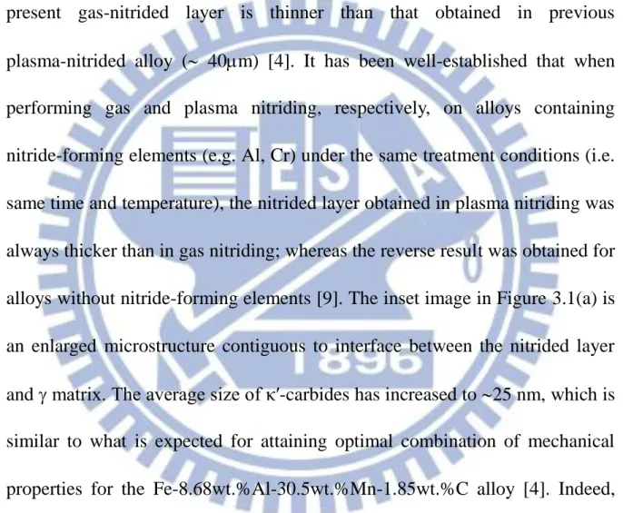
Figure 3.1(a) is the cross-sectional SEM image of the present gas-nitrided
alloy, revealing that the nitrided layer is 30 m-thick with the top-most 2 m exhibiting very white appearance. It is noteworthy that the thickness of the
present gas-nitrided layer is thinner than that obtained in previous
plasma-nitrided alloy ( 40m) [4]. It has been well-established that when performing gas and plasma nitriding, respectively, on alloys containing
nitride-forming elements (e.g. Al, Cr) under the same treatment conditions (i.e.
same time and temperature), the nitrided layer obtained in plasma nitriding was
always thicker than in gas nitriding; whereas the reverse result was obtained for
alloys without nitride-forming elements [9]. The inset image in Figure 3.1(a) is
an enlarged microstructure contiguous to interface between the nitrided layer
and matrix. The average size of κ′-carbides has increased to 25 nm, which is similar to what is expected for attaining optimal combination of mechanical
properties for the Fe-8.68wt.%Al-30.5wt.%Mn-1.85wt.%C alloy [4]. Indeed,
the ultimate tensile stress (UTS), yield strength (YS), and elongation (El) of the
present gas-nitrided alloy are 1390 MPa, 1292 MPa, and 33.2%, respectively,
The results are comparable to those obtained for the same alloy after being
plasma nitrided at 500C for 8h (1402 MPa, 1298 MPa, and 34.5%)[4]. Figures 3.1(b) through Figure 3.1(e) show the elemental mapping in the rectangular
region marked in Figure 3.1(a). The results clearly delineate that Al has
diffused outward and accumulated in the vicinity of surface to interact with
inward-diffusing N. On the contrary, the concentrations of Fe and Mn in the
nitrided layer appear to be less than those in the -matrix. The XRD results shown in Figure 3.1(f) reveal that the nitrided layer is composed predominantly
of nano-crystalline AlN (5~10 nm) with a small amount of Fe4N. Moreover, the
diffraction peaks of the -phase appear to be significantly broadened and shift to the lower diffraction angles, indicative of strained and expanded lattice
arising from nitrogen incorporation [10]. This is similar to that observed
previously in plasma nitriding of the same alloy [4].
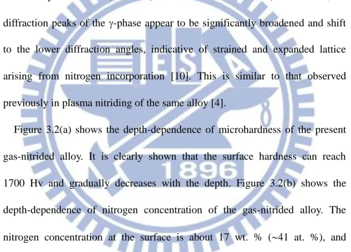
Figure 3.2(a) shows the depth-dependence of microhardness of the present
gas-nitrided alloy. It is clearly shown that the surface hardness can reach
1700 Hv and gradually decreases with the depth. Figure 3.2(b) shows the
depth-dependence of nitrogen concentration of the gas-nitrided alloy. The
nitrogen concentration at the surface is about 17 wt. % (41 at. %), and exhibits an apparent plateau within the first several m. Potentiodynamic polarization curves for the as-quenched and gas-nitrided alloys in 3.5% NaCl
solution is shown in Figure 3.2(c). Evidently, for the untreated alloy, there is no
apparent passivation region. The corrosion current density (icorr)and corrosion
potential (Ecorr) are 2×10
-6
current density (Icorr), corrosion potential (Ecorr), pitting corrosion current
density (Ip), pitting potential (Epit) and △ E(Epit - Ecorr) were measured to be
510-6 A-cm-2, +25 mV, 910-9 A-cm-2, +25 mV and +1710mV, respectively. Evidently, the surface microhardness and corrosion resistance behavior of the
gas-nitrided alloy are slightly lower than those obtained by plasma nitriding [4].
The slight differences in surface hardness and corrosion resistance are due to
the differences in thickness and compositions of the nitrided layer. Nevertheless,
we emphasize here that such values of microhardness and corrosion resistance
are still far superior to those obtained in optimally nitrided high-strength alloy
steels, martensitic and precipitation-hardening stainless steels [4, 10-12]; In
these high-strength body-centered cubic (B.C.C.) steels, the nitrided layer is
mainly composed of Fe3N (hexagonal close packed, hcp) and Fe4N (fcc),
without or with a trace of CrN (fcc), and the surface nitrogen concentration is
in the range of 10~15 wt.% [13-15]. It is known that higher nitrogen
concentration and dense packing of finer nitride particles can considerably
improve the surface hardness and corrosion resistance of the nitrided alloys
[13-15]. Figure 3.2(d) clearly indicates that the surface of the nitrided layer
consists of very dense and extremely fine AlN nitride particles, which
combining with the high nitrogen concentration near the surface thus explained
Next we will discuss the fracture behaviors of the nitrided layer, which have
been largely ignored, despite that both gas and plasma nitriding have been
ubiquitously applied to metal alloys, for improving surface microhardness and
corrosion resistance. Figure 3.3(a) is a SEM image taken from the free surface
of the nitrided-alloy after tensile test. There are several salient features to be
noted: (1) the nitrided layer deforms commensurately with the underneath - matrix along the direction of applied stress; (2) the top-most nitrided layer
fractures evenly with cracks running perpendicular to the stress direction; (3)
the fractured fragments do not spall and detach from the substrate; (4) the
fractured layer is 1.7 m-deep (AFM image in Figure 3.3(b)), which is consistent with the thickness of the white thin layer seen in Figure 3.1(a); (5)
the wavy morphology of the fractured layer also suggests that even AlN layer is
not completely brittle, presumably due to the uniform nano-sized
microstructure and/or substantial nitrogen concentration existing in this layer is
less than that of the stoichiometric AlN (N~50 at.%). Moreover, the tilted SEM
image shown in Figure 3.3(b) revealing simultaneously the free and fracture
surfaces indicates that there are high density of dimples existing within the
+κ′-carbides matrix, while no microvoids or microcracks can be observed in the vicinity of the interface, albeit the fracture surface of the nitrided layer does
deformation and excellent adhesion between the nitrided layer and substrate
may be attributed to the fact that AlN, Fe4N, -matrix and -carbides all are
having the same fcc crystal structure with very similar lattice parameters [4].
Finally, we turn to the edge effect on gas nitriding process. Figure 3.4 shows a
typical gas-nitrided layer around a sharp sample corner. Clearly, the thickness
of the nitrided layer around the corner is thicker than that of the nearby straight
regions, which is in contrast to what is usually seen in plasma nitriding [6],
suggesting that gas nitriding maybe more favorable for processing components
3-4 Conclusions
Due to contain high content of strong nitride-forming element Al, the nitrided
layer consists predominantly of nano-crystalline AlN with a small amount of
Fe4N in the present Fe-9wt.%Al-28wt.%Mn-1.8wt.%C alloy after being
gas-nitrided at 500C for 8h, The resultant nitrided layer accounts for the large surface microhardness (1700 Hv), and the superior corrosion resistance in 3.5% NaCl solution, as well as the coherent and adhesive fracture behavior
obtained. Moreover, gas nitriding appears to yield more uniform nitrided layer
References
[1] K.M. Chang, C.G. Chao, T.F. Liu, Scripta Mater. 63 (2010) 162.
[2] W.K. Choo, J.H. Kim, J.C. Yoon, Acta Mater. 45 (1997) 4877.
[3] I. Kalashnikov, O. Acselrad, A. Shalkevich, L.C. Pereira, J. Mater. Eng.
Perform. 9 (2000) 597.
[4] P.C. Chen, C. G. Chao, T.F. Liu, Scripta Mater. 68 (2013) 380.
[5] P. Kochmanski, J. Nowacki, Surf. Coat. Technol. 202 (2008) 4834.
[6] S.D. de Souza, M. Kapp, M. Olzon-Dionysio, M. Campos, Surf. Coat.
Technol. 204 (2010) 2976.
[7] J. Bielawski. J. Baranowska, K. Szczecinski, Surf. Coat. Technol. 200 (2006)
6572.
[8] Yucel Birol, Eng. Failure Anal. 26 (2012) 203.
[9] F. Ashrafizadeh. Surf. Coat. Technol. 173~174 (2003) 1196.
[10] C.X. Li, T. Bell, Corrosion Science 48 (2006) 2036.
[11] Y. Li, L. Wang, D. Zhang, L. Shen, Applied Surface Science, 256 (2010)
4149.
[12] R.F. Liu, M.F. Yan, Mater. Des. 31 (2010) 2355.
[13] W.P. Tong, N.R. Tao, Z.B. Wang, J. Lu, K. Lu, Science 299 (2003) 686.
[14] G. J. Li, J. Wang, Q. Peng, C. Li, Y. Wang, B. L. Shen, J. Mater. Proc.
Figure 3.1(a)
Figure 3.1(c)-(N mapping)
Figure 3.1(f)
Figure 3.1 (a) SEM cross-sectional image of the gas-nitrided alloy. Inset image
shows the enlarged microstructure near the interface. (b) ~ (e) The
elemental mapping images taken from the rectangular region
marked in (a) for Al、 N、Mn and Fe, respectively. (f) XRD results
Figure 3.2(a)
Figure 3.2(d)
Figure 3.2 (a)Nitrogen concentration profile of the present gas-nitrided alloy.
(b)Hardness profile of the present gas-nitrided alloy. (c)
Polarization curves for the present as-quenched and gas-nitrided
alloys in 3.5% NaCl solution. (d) SEM surface image of the
Figure 3.3(a)
Figure 3.3(c)
Figure 3.3 (a) SEM image of the free surface of gas-nitrided alloy after tensile
test. (b) AFM image of one of the fractured fragment. (c) SEM image
Figure 3.4