Fuh-Kuo Chen
Associate Professor,
Bai-Hong Chiang
Graduate Student,
Department of Mechanical Engineering, National Taiwan University, Taipei, Taiwan, R.O.C.
Three-Dimensional Finite
Element Analysis for the
Stamping of a Motorcycle
Oil Tank
The three-dimensional finite element analysis was performed to determine an optimum die design and the corresponding sheet-blank shape for stamping a part of motorcycle oil tank. To save the computation time, an equivalent drawbead model was adopted to replace the actual drawbead shape in the finite element simulations. The forming limit diagram constructed from stretching tests was also used in conjunction with the finite element results to predict the occurrence of fracture. The optimum die design and the corresponding sheet-blank shape obtained from the finite element analysis was validated by the achievement of defect-free production panels. The advantage of using the finite element analysis for the stamping die design was thereby confirmed.
1 Introduction
The oil tank of a motorcycle usually consists of three stamped parts assembled by welding. Due to keen competition in the market, the styling of the motorcycle must keep up with the latest fashion, and in consequence, the shape of the oil tank becomes more complex. In addition, for the sake of cost-saving, each of the three parts is often drawn to the desired shape only by a single operation, and hence the die design for the stamping process becomes even more difficult. However, since the three-dimensional dynamic/explicit finite element method has been effectively adopted to analyze the sheet-metal forming process in the early 1990's (Galbraith et a l , 1991), the metal-flow pattern could be easily obtained from the computer simulations, being of much help in die design.
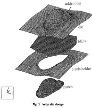
In the present study, the die design and the corresponding sheet-blank shape for stamping the right-hand part of an in-fashion oil tank, as shown in Fig. 1, was investigated using the three-dimensional dynamic/explicit finite element analysis. The stamping of this oil tank is inherently a deep-drawing process, thanks to the part geometry, and the major defects such as fracture and wrinkle, which are observed in most deeply-drawn parts, are to be prevented in the early design stage. Since the part is drawn to the desired shape by one operation, the adden-dum and the drawbead location are the major concerns in the die face design. The addendum is a part of the die surface located outside the trim line, i.e. the boundary of the product shape, but within the die cavity, as indicated in Fig. 2. The drawbead is a small groove on the die surface and is matched by a bead on the blank-holder, as shown in Fig. 3 ( a ) . The addendum shape helps the formability and the use of drawbeads controls the metal-flow from the blank-holder to the die cavity. Taking the above design concepts into consideration, an initial die surface was constructed as shown in Fig. 2. Based on this die configuration, the finite element analyses with the use of an equivalent drawbead model (Aita et al., 1992) were performed to determine the shape of an optimum sheet-blank as well as an improved die surface.
In the equivalent drawbead model, the actual drawbead is replaced by its projection onto the binder surface, i.e., a flat
Contributed by the Manufacturing Engineering Division for publication in the JOURNAL OF MANUFACTURING SCIENCE AND ENGINEERING. Manuscript received Feb. 1996; revised Sept. 1997. Associate Technical Editor: E. Chu.
surface which has the same width as the actual drawbead, and a regular mesh is constructed for the flat surface, as shown by the shaded area in Fig. 3(b). The restraining force produced by the actual drawbead is assigned distributedly to the nodes in the regular mesh of the equivalent drawbead following the virtual work principle. The sheet-metal passing through the equivalent drawbead model is then subjected to the same re-straining force as that produced by the actual drawbead. The use of an equivalent drawbead model eliminates the need for using an extremely fine mesh for the sheet-metal, and in conse-quence, a huge saving of computation time can be achieved. In the present study, the restraining forces were used in the finite element analysis for the drawbead design without considering the actual drawbead shapes. The actual drawbead, which can be derived reversely from the restraining force, is required only when the optimum die design is achieved.
All the simulations performed in the present study were run on an HP735 workstation with the use of the finite element program PAM_STAMP.
2 Finite Element Model
The meshes of stamping dies, as initially designed, were generated by the CAD program STRIM 100, as shown in Fig. 2, with the use of four-node shell elements. In the simulation, the sheet-metal was placed on the blank-holder and the die moved down to clamp the sheet-metal against the blank-holder, so that the shape of binder-wrap was formed. Next, the punch was moved up to draw the sheet-metal to the desired shape. The clamping force exerted by the blank-holder was 150 kN and the total draw depth was 230 mm. To facilitate the simula-tion, the punch speed was set to 10 m/sec and a coefficient of Coulomb friction of 0.05 was assumed. The stress-strain rela-tions obtained from tensile tests was used in the finite element simulations. In addition, a forming limit diagram (FLD) (Keeler and Backofen, 1963) for the sheet-metal constructed from stretching tests was used in conjunction with the finite element results to predict the failure of sheet-metal.
3 Results and Discussions
The finite element simulations were first performed to deter-mine the sheet-blank geometry and both the location and the size of the drawbeads. A modified die surface which was designed to 770 / Vol. 120, NOVEMBER 1998 Transactions of the ASME
Copyright © 1998 by ASME
drawing direction
(a) actual drawbead.
Fig. 1 The right-hand part of an oil tank
eliminate wrinkles was also simulated. The simulation results are summarized and discussed as follows. The effects of the blank-holder pressure and the friction at the interfaces between dies and the sheet-blank were also investigated. But, to limit the length of this paper, the results are not presented here.
3.1 Sheet-Blank and Drawbead Designs. A sheet-blank shape, which was preliminarily designed according to the pe-riphery of the die surface, was used for the initial simulation. In order to observe the metal-flow, no drawbead was added to the die surface for the simulation, and hence the sheet-blank shape, as shown in Fig. 4 ( a ) , was designed to have a larger size so that the sheet-metal would not be completely drawn into the die cavity at the end of the stroke. Since the fracture was to be examined first, a limit strain of 0.4 was set in the finite element simulation such that elements stretched by more than an effective strain of 0.4 would be removed from the mesh. The removal of elements makes it easy to determine the location of the most severely stretched elements.
The simulated shape obtained for the initial sheet-blank shape is shown in Fig. 4(b). As seen in this figure, considerable amounts of stretching occurred at the top of the stamped part, at which some elements were removed from the mesh. The distribution of the major and minor principal strains plotted in the FLD also indicates that the simulated part was close to the
addendum
*&
4. > v % •////?-?: ^ .
i . » ipunch
Fig. 2 Initial die design
Journal of Manufacturing Science and Engineering
S
blank-holder / ' ' ' ' ' ' < ' ' ' ' ' ' ' ' sheet-metal < s r / / / / s s / / ; / / s /—7* drawing , binder direction ' ' ' /^x\\y^y\sy\\x\sy\sy\^x\w J / /* ^equivalent drawbead (b) equivalent drawbead model.Fig. 3 Drawbead configurations (a) actual drawbead (fa) equivalent drawbead model
point of fracture. It is also noticed that the amount of metal-flow is quite small except in the lower portion of the blank. Both the geometries of die cavity and sheet-blank size accounted for this small amount of metal-flow. The die cavity had a shorter length in the y direction, so the sheet-metal on the upper and the lower sides in the y direction were more easily drawn into the die cavity than that on the right-hand and the left-hand sides in the x direction. The large size of the sheet-blank restrained the metal flowing toward the die cavity from the blank-holder except on the lower side which had less metal under the blank-holder. The low degree of metal-flow from the blank-holder was also the major reason causing the fracture of the simulated part.
Following the observation of the metal-flow obtained from the finite element simulation, as shown in Fig. 4(b), the draw-bead was divided into five portions, as shown in Fig. 5, and were denoted by dbl, db2, db3, db4, and db5, respectively; so that a more precise control of metal-flow could be achieved. The finite element simulations have been performed for several different shapes of sheet-blank and different distributions of drawbeads, according to the metal-flow analysis. An optimum shape of sheet-blank, as shown in Fig. 6 ( a ) , and drawbead distribution (dbl, db2, db3, db4, db5) = (0, 0.015, 0, 0.035, 0) kN/mm, resulting in an acceptable final shape, as shown in Fig. 6(b), was determined. The radii of the drawbead profiles corresponding to the restraining forces 0.015 kN/mm and 0.035 kN/mm produced were determined from the finite element sim-ulations to be 16 mm and 8 mm, respectively.
It can be seen in Fig. 6(b) that no element at the top area was removed from the mesh. The distribution of major and minor principal strains, as plotted in the FLD shown in Fig. 7, also indicates that the top portion of the simulated part was free from fracture. The residual metal on the left-upper side seemed to be significant. However, if we reduce the metal in this area, the metal may be completely drawn into the die cavity. Hence, the final configuration resulted from the this sheet-blank shape and the redesigned drawbeads can be considered acceptable.
3.2 Modified Die Design. Although the above die design results in an acceptable part shape in terms of optimum sheet-blank shape and fracture-free product, wrinkles are found at the
NOVEMBER 1998, Vol. 120 / 771
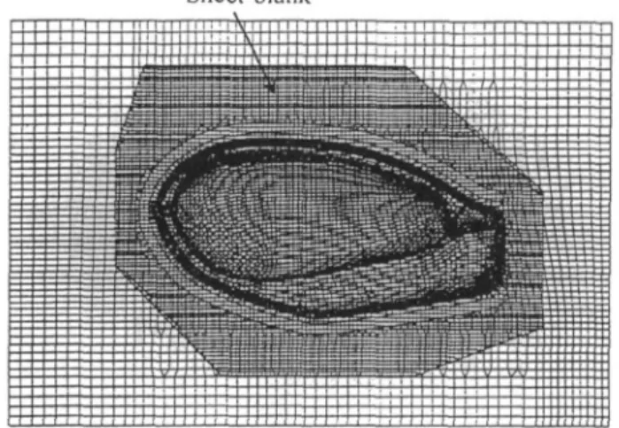
Sheet-blank
(a) initial sheet-blank shape.
(b) simulated shape.
Fig. 4 Initial and simulated shapes for the originally designed sheet-blank (a) initial sheet-sheet-blank shape (fa) simulated shape
top of the addendum, as shown in Fig. 6(b). Since the occur-rence of wrinkles is due to redundant metal gathered at certain locations and subjected to compressive stress, a straightforward method of suppressing the wrinkles is to add artificial draw-bars in the wrinkled area to absorb the redundant metal. It is obvious that the added draw-bars should not be within the trim line, i.e., the part shape, and hence, it can only be added to the addendum. It is also to be noted that the draw-bars should be added parallel to the direction of wrinkles so that the redundant
Fig. 5 Drawbead locations
Sheet-blank
(a) initial sheet-blank shape.
(b) simulated shape.
Fig. 6 Initial and simulated shapes for the optimum sheet-blank (a) initial sheet-blank shape (fa) simulated shape
metal can be absorbed effectively. Hence, two draw-bars paral-lel to the direction of wrinkles were added to the addendum, as shown in Fig. 8, for eliminating wrinkles. Such a modification was not expected to introduce any significant change of defor-mation pattern at the top portion of the oil tank. The final shape obtained by the finite element simulation for the modified die design is shown in Fig. 9. As seen in this figure, the wrinkles disappear while the major and minor strains are still in the the safe zone of the FLD.
With the modified die design and the drawbead radii obtained from the finite element analyses, the actual stamping dies for the production purpose were manufactured and the production part was found to be free from defects. The part shape also agreed very well with that obtained by the finite element simula-tion. The defect-free product confirmed the advantage of using the finite element analysis for the stamping die design.
A further validation of the finite element simulations was made by the comparison of the thickness distributions between
772 / Vol. 120, NOVEMBER 1998 Transactions of the ASME
Fig. 7 The FLD for the optimum sheet-blank
draw-bar
Fig. 8 Draw-bars added to the addendum
Fig. 9 Simulated shape for the modified die design
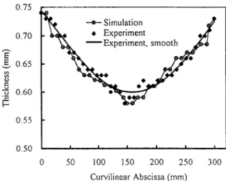
the simulation results and the production panel. Figure 10 shows the thickness distribution measured by an ultrasonic instrument and those obtained from the finite element simulation along the section A-A of the production component, as shown in Fig. 9. It is to be noted that the measured data indicate smooth changes at two sides of the production component but are scattered at the top. The reason for the scatter is that the diameter of the
0.75
0.55
-0.50 I 1 " " 1 ' 1—J 0 50 100 150 2 0 0 2 5 0 3 0 0
Curvilinear A b s c i s s a ( m m )
Fig. 10 The predicted and measured thickness distribution
ultrasonic probe is too big to operate properly at the large curva-ture area such as the top of the production part. Since the thick-ness distribution at the production part is expected to vary smoothly, the measured data interpolated by the best-fit curve, as shown in Fig. 10, may be a better representation of the actual thickness distribution. It can be seen in Fig. 10 that the measured data agree very well with the thickness distribution predicted by the finite element simulation. This remarkable agreement once again validates the capability of the finite element analysis.
4 Concluding Remarks
The substitution for the die try-outs is the major advantage of using the finite element simulations for the stamping die design. All the modifications for the die design can be made on a computer in the design stage instead of revamping the actual steel dies during the die try-outs. In the present study, the optimum sheet-blank shape and both the sizes and locations of the drawbeads were efficiently determined from the finite element analysis. The modified die surface designed for elimi-nating the wrinkle defect was also confirmed by the simulation. The optimum die design obtained from the finite element analy-sis was validated by the defect-free production panels. The agreement between the simulation results and those observed in the actual practice shows that the three-dimensional finite element analysis has been one of the most useful tools for the stamping die design for the production of complex components.
Acknowledgment
The authors wish to thank the National Science Council of the Republic of China for their grant NSC-84-212-E002-081 which makes this project possible.
References
Aita, S., Khaldi, E. L„ Fontaine, L., Tamada, T., and Tamura, E„ 1992, "Nu-merical Simulation of a Stretch Drawn Autobody: Part I—Assessment of Simula-tion Methodology and Modelling of Stamping Components," SAE Paper No. 920639.
Galbraith, P. C , Finn, S. R„ MacEwen, S. R., Carr, A. R„ Gateby, K. M„ Lin, T. L., Clifford, G. A., Hallquist, J. O., and Stillman, D„ 1991, "Evaluation of an LS-DYNA3D Model for Deep-Drawing of Aluminum Sheet," VD1 Berichte NR, Vol. 894, pp. 441-466.
Keeler, S. P., and Backofen, W. A., 1963, "Plastic Instability and Fracture in Sheets Stretched Over Rigid Punches," Trans ASM, Vol. 56, pp. 25-48.
Journal of Manufacturing Science and Engineering NOVEMBER 1998, Vol. 120 / 773