Abstract—With continuous rise of oil price, how to develop alternative energy source has become a hot topic around the world. This study discussed the dynamic characteristics of an island power system operating under random wind speed lower than nominal wind speeds of wind turbines. The system primarily consists of three diesel engine power generation systems, three constant-speed variable-pitch wind turbines, a small hydraulic induction generation system, and lumped static loads. Detailed models based on Matlab/Simulink were developed to cater for the dynamic behavior of the system. The results suggested this island power system can operate stably in this operational mode. This study can serve as an important reference for planning, operation, and further expansion of island power systems.
Keywords—Diesel engine power generation system, constant-speed variable-pitch wind turbine, small hydraulic induction generation system, penetration, Matlab/Simulink, SimPowerSystems.
I.INTRODUCTION
Nrecent years, with continuous rise of oil price, how to develop alternative energy source has become a hot topic around the world. After the Kyoto Protocol has been exercised, a new trend of international environment protection has emerged, and various industries in Taiwan have proposed suggestions for new energy policy. Since “The 2nd National Energy Conference,” the government has set CO2 control mechanism actively and expected decrease of 38 million MT by the end of 2015, 58.68 million MT by 2020, and 78.41 million MT by 2025. The utilization of renewable energy is expected to reach 7,000~8,000MW by 2020 and 8,000~9,000MW by 2025, to attain the goal for total installed capacity penetration 12% or energy structure penetration 4~6%. The renewable energy development projects include biomass, wind power, photovoltaic system, solar heat, hydrogen energy, fuel cell, oceanic energy, geothermal heat, etc. The projects also cover planning offshore wind farms with scale of economy and fostering the development of the domestic wind industry [1].
Diesel engine power generation systems are commonly used to supply relatively small capacity systems such as island
Meng-Jen Chen is with the Department of Electrical Engineering, National Kaohsiung University of Applied Sciences, Kaohsiung, Taiwan (e-mail: [email protected]).
Yui-Chi Wu is with the Department of Electrical Engineering, National United University, Miao-Li, Taiwan (corresponding author: +886-37-381362; fax: +886-37-327887; e-mail: [email protected]).
Guo-Tsai Liu and Sen-Feng Lin are with the Department of Electrical Engineering, National Kaohsiung University of Applied Sciences, Kaohsiung, Taiwan.
power systems, industrial power systems, and marine power systems. Especially, in many remote regions or islands, the electric power from central power stations is difficult to be transmitted to these places. The diesel engine power generation becomes the most commonly used power generation technology in these regions because the diesel engine has advantages of easy start-up, low equipment cost, short plant construction period, and stable voltage and frequency control. However, the power quality problem resulted from small capacity ratio between the power generation system and load has to be concerned. Combining the diesel engine with other renewable energy power supplies to form a hybrid system to maintain acceptable power quality and reliable electricity supply is an economical way to reduce the fuel cost and the pollution caused by fossil fuels [2], [3].
Many studies have been done on island power systems and hybrid power systems. Reference [4] proposed an algorithm for optimizing the assemblies of stand-alone wind-diesel hybrid power generation system and used a prototype system to verify the dynamic characteristics of two generators under optimal load distribution. Reference [5] discussed the power quality problem of a stand-alone island power system with high penetration of wind energy and indicated that the torque variation in diesel engine was the main cause for voltage flicker. Reference [6] proposed an automatic reactive power control strategy for stand-alone wind-diesel hybrid power system which consisted of a wind power generation system with permanent magnet generator and a diesel engine power generation system with synchronous generator. Reference [7] discussed the dynamic behavior simulation of a hybrid system comprising diesel engine and variable-speed wind turbine and proved that the power quality could be improved by controlling the frequency. Reference [8] discussed the dynamic characteristics of wind-diesel hybrid systems used in remote regions, including coupling problem, mutual interference of interconnected systems, improvement on reactive power, reduction of wind turbine output loss, etc. Reference [9] analyzed and designed the control method for a stand-alone wind-diesel hybrid system at different frequencies. Reference [10] discussed the influence of power quality on the wind-diesel hybrid system and the problems caused by load and frequency switching. Reference [11] used genetic algorithm to adjust static reactive power compensator, so the system could control the reactive power within an ideal range automatically. Reference [12] discussed the control system used for wind-diesel hybrid system with high wind power. Few of these
Meng-Jen Chen, Yu-Chi Wu, Guo-Tsai Liu, and Sen-Feng Lin
Performance Analysis of an Island Power System
Including Wind Turbines Operating under Random
Wind Speed
I
studies have used detailed dynamic pitch
analyze the dynamic characteristics of an island power system with high renewable energy penetration.
This study discussed the dynamic characteristics of an island power system under random wind speed. This study is essential for planning, operation, and further expansion of
systems.
II.ISLAND POWER SYSTEM
A.Configuration of an Island Power System
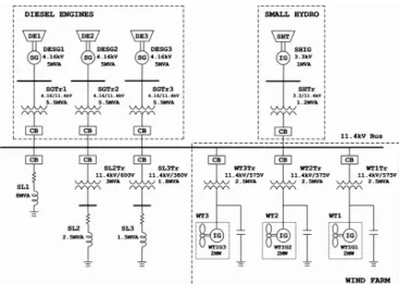
Fig. 1 shows the configuration of a simplified island power system. The system consists of three diesel engine power generation systems, three constant-speed variable
turbines, a small hydraulic inductive generation system, and lumped static loads. Each diesel engine power generation system is rated 5MVA, consisting of a diesel engine, a synchronous generator, an excitation system, and a transformer. Each constant-speed
variable-rated 2MW, consisting of blades, a mechanical transmission system, an induction generator, and a transformer. The small hydraulic power generation system is rated 1M
of a small hydraulic turbine, an induction generator, and a transformer. The diesel engine power generation systems are the main power sources, and the output voltage is 11.4kV. The minimum load of this system is 4MVA, and the maximum load is 12MVA.
Fig. 1 Configuration of a simplified islan
B.Diesel Engine Model
The diesel engine prime mover model is usually developed by using the engine performance data provided by the manufacturer. Fig. 2 shows the schematic diagram of a diesel engine prime mover. This model consists of three s
thermodynamic model, speed governing model, and shaft model [13].
dynamic pitch-control models to characteristics of an island power system This study discussed the dynamic characteristics of an island power system under random wind speed. This study is essential for planning, operation, and further expansion of island power
YSTEM
Configuration of an Island Power System
1 shows the configuration of a simplified island power system. The system consists of three diesel engine power speed variable-pitch wind turbines, a small hydraulic inductive generation system, and lumped static loads. Each diesel engine power generation system is rated 5MVA, consisting of a diesel engine, a synchronous generator, an excitation system, and a -pitch wind turbine is rated 2MW, consisting of blades, a mechanical transmission system, an induction generator, and a transformer. The small rated 1MVA, consisting ion generator, and a transformer. The diesel engine power generation systems are the main power sources, and the output voltage is 11.4kV. The minimum load of this system is 4MVA, and the maximum load
Configuration of a simplified island power system
The diesel engine prime mover model is usually developed by using the engine performance data provided by the 2 shows the schematic diagram of a diesel engine prime mover. This model consists of three subsystems-- thermodynamic model, speed governing model, and shaft
Fig. 2 Schematic diagram of a diesel engine prime mover
Under normal circumstances, the engine torque is proportional to the fuel. In the case of sufficient air supply, the fuel can be combusted completely, so the torque can be regarded as proportional to the fuel tank level. However, in the case of transient and heavy load, the fuel cannot be combusted completely, and the torque is limited to the air supply. The turbocharger is usually installed to improve the situation.
The speed adjustment is implemented by the speed governing system of prime mover. When the generator speed deviates from the rated speed, the governor mechanism will detect the variation in rotational speed. Th
valve is changed and the output of prime mover is adjusted to make the speed steady. Fig.
typical governing arrangement.
Fig. 3 Block diagram of typical governing arrangement
The state equation of this diagram can be expressed as
1 1 1 2 2 2 2 3 D1 2 D 1 3 23 23 3 4 4 D1D 3 D 3 2 D 1 3 D 3 234 234 3 4 4 1 0 0 0 T x 1 1 x T T x x p x KT K ( T T ) x T T T T T x x KT T KT ( T T ) T T ) T T T T T T T T T − − = + − − − − D 1 D 1 2 K 1 2 2 2 T T x K [ x ( 1 ) x ] T T = + − D 1 D 3 D 3 D 1 3 D 3 D 3 3 K 1 2 3 ref 2 3 2 3 3 3 KT T KT ( 1 T ) T T T x x x x P T T T T T T − − = + + +
where ωe is the engine speed,
speed, Pref is the reference power.
The mechanical shaft model can be represented by the torsional model of a simple two
[14]. As the system is represented by second
Schematic diagram of a diesel engine prime mover
Under normal circumstances, the engine torque is proportional to the fuel. In the case of sufficient air supply, the el can be combusted completely, so the torque can be regarded as proportional to the fuel tank level. However, in the case of transient and heavy load, the fuel cannot be combusted completely, and the torque is limited to the air supply. The
s usually installed to improve the situation. The speed adjustment is implemented by the speed governing system of prime mover. When the generator speed deviates from the rated speed, the governor mechanism will detect the variation in rotational speed. The position of transfer valve is changed and the output of prime mover is adjusted to Fig. 3 shows the block diagram of typical governing arrangement.
Block diagram of typical governing arrangement
s diagram can be expressed as
1 1 1 1 2 2 3 3 3 23 23 3 4 4 D 3 D 1D 3 D 3 2 D1 3 D 3 3 4 23 4 23 4 3 4 4 0 0 0 1 1 0 0 T T x x 0 0 0 0 0 0 x x 1 0 0 0 x 1 x 0 T T T T T T x x KT 0 0 0 KT T KT ( T T ) T T ) 1 T T T T T T T T T T T − = + − − − − e ref ref P 0 ϖ ϖ (1) D 1 D 1 2 K 1 2 2 2 T T x K [ x ( 1 ) x ] T T = + − (2) D 1 D 3 D 3 D 1 3 D 3 D 3 3 K 1 2 3 ref 2 3 2 3 3 3 KT T KT ( 1 T ) T T T x x x x P T T T T T T − − = + + + (3)
is the engine speed, ωref is the reference rotational
is the reference power.
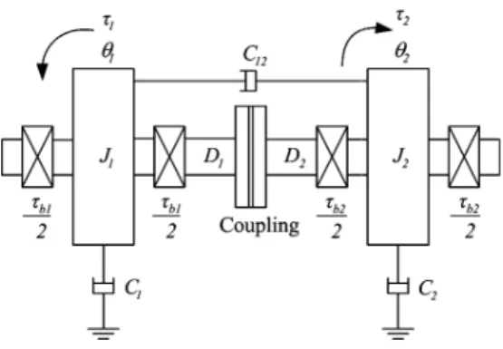
echanical shaft model can be represented by the torsional model of a simple two-mass system as shown in Fig. 4 . As the system is represented by second-order differential
equations in angular displacement θ1 of mass 1 and angular
displacement θ2 of mass 2, the system will have the undamped
natural frequency given by (π/2)(D/J1+D/J
This system can be expressed as
1 1 12 12 1 1 1 1 1 1 1 1 1 2 2 2 12 2 12 2 2 2 2 2 0 1 0 0 0 0 0 0 C C C D D 1 1 J J J J J J p 0 0 0 1 0 0 0 0 C C C 1 1 D D 0 0 J J J J θ θ ω ω θ θ ω ω − − − − = + − − − − −
where J1 is the inertia of rotating mass 1 including coupling,
is the inertia of rotating mass 1 including coupling, stiffness of shaft 1, D2 is the stiffness of shaft 2,
damping coefficient of mass 1, C2 is the damping coefficient of
mass 2, C12 is the mutual damping coefficient of mass 1 and
mass 2, τb1 is the bearing loss torque of mass 1,
loss torque of mass 2, and D is the sum of
Fig. 4 Torsional model of a two-mass system
C.Constant-Speed Variable-Pitch Wind Turbine Model
The air flow produces wind pressure to rotate wind turbine blades, and the mechanical power is delivered to the generator through the transmission system. Therefore, the order of wind energy conversion is that the kinetic energy of wind is converted into mechanical energy and then into electric energy. The principle for blade pitch angle control includes comparing the real power of wind turbine with the reference power, sending the signal to a gain, limiting the upper and lower limits of the value, and adjusting the wind turbine blade pitch angle. The reference power can be determined
power curve.
According to the aerodynamics, the wind turbine output power can be expressed as
3 ( , ) 2 w p wind A P =c λ β ρ v 1.5 p 1 2 3 4 5 c =c ( c −cβ −c β −c )e
where λ is the blade tip speed ratio, β is the blade pitch angle, is the air density, A is the blade swept area,
velocity, and cp is the power coefficient,
of mass 1 and angular s 2, the system will have the undamped
+D/J2)1/2. 1 1 1 1 1 1 1 b1 2 b2 2 2 0 0 0 0 D D 1 1 0 0 J J J J J J 0 0 0 1 0 0 0 0 C C C 1 1 0 0 J J τ τ τ τ − − − − − − (4)
is the inertia of rotating mass 1 including coupling, J2
uding coupling, D1 is the
is the stiffness of shaft 2, C1 is the
is the damping coefficient of is the mutual damping coefficient of mass 1 and mass 1, τb2 is the bearing
is the sum of D1 and D2.
mass system
Wind Turbine Model
The air flow produces wind pressure to rotate wind turbine anical power is delivered to the generator through the transmission system. Therefore, the order of wind energy conversion is that the kinetic energy of wind is converted into mechanical energy and then into electric energy. ngle control includes comparing the real power of wind turbine with the reference power, sending the signal to a gain, limiting the upper and lower limits of the value, and adjusting the wind turbine blade pitch angle. by the wind turbine According to the aerodynamics, the wind turbine output
w p wind (5) 6
c ( , )
p 1 2 3 4 5
c c ( c c c c )e− λ β (6) is the blade pitch angle, ρ is the blade swept area, vwind is the wind
is the power coefficient, c1=0.5, c2=116/λi,
c3=0.4, c4=0, c5=5, c6=21/λi,
λ λ β β
The random wind speed emplo expressed as 1 2 [ ( ) ] cos( ) N WN V i i i i V S ω ω ωt φ = =
∑
∆ + ( 1/ 2) i i ω = − ∆ω 2 2 4 / 3 ( ) [1 ( / ) ] V i S ω π ω µπ =where
φ
i is a random distribution is surface resistance coefficient,the average wind speed in m/s [16]. Reference [16] suggested that there will be relatively good results for disturbance wind simulation in the case of N equal to
2.0rad/s.
D.Small Hydraulic Turbine Model
Small hydro power is an environmental friendly energy resource. It is clean, renewable and can be made to be unobtrusive. In addition, hydro turbines are associated with maintenance and long life and produce energy which reduces the use of fossil fuel. Within the category of small hydro plant a wide range of turbine types are available.
Simpler modeling procedure for small hydro turbines in conjunction with induction generators have been
practice over a number of years.
versus speed for a mid-range unit when the input torque is a constant. Apply a curve-fitting
curve can be represented by a polynomial for simulation.
Fig. 5 Characteristics of the small
E.Synchronous Generator Model
A synchronous generator requires a prime mover to supply mechanical power and an excitation system to supply excitation voltage when it is in operation. The stator
synchronous generator is three
rotor structure is either salient or cylindrical. The voltage equation of a synchronous generator referring to rotor can be expressed as 3 1 1 0.035 0.08 1 i λ =λ+ β−β + [15].
The random wind speed employed in this study can be
1/ 2 2 [ ( ) ] cos( ) WN V i i i V = S ω ∆ω ωt+φ (7) (i 1/ 2) ω = − ∆ω (8) 2 2 2 4 / 3 2 [1 ( / ) ] N i i K F F ω π + ω µπ (9)
distribution value between 0 and 2π, KN
is surface resistance coefficient, F is scale of disturbance, µ is the average wind speed in m/s [16]. Reference [16] suggested that there will be relatively good results for disturbance wind equal to 50 and ∆ω between 0.5 and
Small Hydraulic Turbine Model
Small hydro power is an environmental friendly energy resource. It is clean, renewable and can be made to be unobtrusive. In addition, hydro turbines are associated with low long life and produce energy which reduces the use of fossil fuel. Within the category of small hydro plant a wide range of turbine types are available.
Simpler modeling procedure for small hydro turbines in conjunction with induction generators have been validated in practice over a number of years. Fig. 5 shows the output torque range unit when the input torque is a fitting technique; the torque-speed curve can be represented by a polynomial for simulation.
Characteristics of the small-hydro turbine prime mover
Synchronous Generator Model
A synchronous generator requires a prime mover to supply mechanical power and an excitation system to supply excitation voltage when it is in operation. The stator structure of a synchronous generator is three-phase symmetrical, and the rotor structure is either salient or cylindrical. The voltage equation of a synchronous generator referring to rotor can be
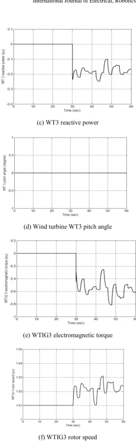
(c) WT3 reactive power
(d) Wind turbine WT3 pitch angle
(e) WTIG3 electromagnetic torque
(f) WTIG3 rotor speed
Fig. 13 Variation of variables of the third wind turbine
IV.DISCUSSIONS
The purpose of this study was to realize the dynamic behavior of an island power system under random wind speed lower than nominal wind speeds of wind turbines. The results show the output power of diesel engine power generation systems was 0.8pu when static loads were connected and
decreased to around 0.55pu after the renewable energy power generation systems had supplied power to the system. The power shared by the renewable energy power systems reached 0.25pu accounting for a penetration of 45%. The pitch angle of wind turbines was not adjusted because the wind speeds were less than the nominls of wind turbines. The output power of wind turbine fluctuated with the variation of wind speed. In contrast, the output power of small hydraulic turbine was stable due to the constant water flow. Overall, the system can run stably in this operational mode, and the variations of system variables are reasonable. The research results are coincident with expectation.
V.CONCLUSIONS
The objective of this study was to investigate the dynamic behavior of an island power system under random wind speed. The results suggested the system can operate stably in this operational mode. This study can serve as an important reference for planning, operation, and further expansion ofisland power systems. Future studies will include other renewable energy systems such as photovoltaic system and variable-speed wind turbine for more understanding of their influence on the dynamic behavior of island power systems.
REFERENCES
[1] http://www.moeaboe.gov.tw/Policy/98EnergyMeeting/conclusion/concl usion_3.html.
[2] Taiwan Power Company, http://www.taipower.com.tw.
[3] Borbely, J. Kreider, Distributed Generation: The Power Paradigm for the
New Millennium, CRC Press, 2001.
[4] T.K. Saha and D. Kastha, “Design Optimization and Dynamic Performance Analysis of a Stand-Alone Hybrid Wind-Diesel Electrical Power Generation System,” IEEE Transactions on Energy Conversion, vol. 25, no. 4, pp. 1209-1217, Dec. 2010.
[5] K. Uhlen, B.A. Foss, and O.B. Gjosater, “Robust Control and Analysis of a Wind-Diesel Hybrid Power Plant,” IEEE Transactions on Energy
Conversion, Vol. 9, Dec. 1994, pp.701-708.
[6] P. Sharma and T. Bhatti, “Performance Investigation of Isolated Wind-Diesel Hybrid Power Systems with WECS having PMIG,” IEEE
Transactions on Industrial Electronics, Vol. PP, Issue 99, pp. 1-8, 2011
[7] S.S. Murthy, S. Mishra, G. Mallesham, and P.C. Sekhar, “Voltage and Frequency Control of Wind Diesel Hybrid System with Variable Speed Wind Turbine,” 2010 Joint International Conference on Power
Electronics, Drives and Energy Systems (PEDES), 2010, pp. 1-6.
[8] H. Sharma, S. Islam, C.V. Nayar, and T. Pryor, “Dynamic Response of a Remote Area Power System to Fluctuating Wind Speed,” IEEE Power
Engineering Society Winter Meeting, Vol. 1, Jan. 2000, pp.499-504.
[9] S.A. Papathanassiou and F. Santjer, “Power-Quality Measurements in an Autonomous Island Grid with High Wind Penetration,” IEEE
Transactions on Power Delivery, vol. 21, no. 1, pp. 218-224, Jan. 2006
[10] E. Muljadi and H.E. McKenna, “Power Quality Issues in a Hybrid Power System,” IEEE Transactions on Industry Applications, Vol. 38, No.3, May/June 2002, pp.803-809.
[11] R.C Bansal, T.S Bhatti, and D.P. Kothari, “Automatic Reactive Power Control of Wind-Diesel-Micro-Hybrid Autonomous Hybrid Power Systems Using ANN Tuned Static Var Compensator,” Large Engineering
Systems Conference on Power Engineering, May 2003, pp.182-188.
[12] R. Sebastian, M. Castro, E. Sancristobal, F. Yeves, J. Peire, and J. Quesada, “Approaching hybrid wind-diesel systems and Controller Area Network,” IECON 02, Vol. 3, Nov. 2002, pp.2300-2305.
[13] J. Delesalle and I. Kauffmann, “Réponse Des Moteurs Diesel Suralimentés Aux Variations Rapides De Puissance Appelée Simulation Mathématique Et Applications,” CIMAC, A, 1977, Pap. A9.
[14] J.R. Smith, A.F. Stronach, and T. Tsao, “Digital simulation of marine electro-mechanical drive systems,” IEEE Transactions on Industry
Applications, IA-18, 1982, pp.393-399.
[15] S. Heier, Grid Integration of Wind Energy Conversion Systems John Wiley & Sons Ltd., June 2006.
[16] P. M. Anderson and A. Bose, “Stability Simulation of Wind Turbine Systems,” IEEE Transactions on Power Apparatus and Systems 102, No. 12, pp.3791-3795, Dec. 1983.
[17] P.C. Krause, Analysis of Electric Machinery and Drive System, 2nd Ed, McGRAW-Hill Book Co., USA, Dec 2001.
[18] C.-M. Ong, Dynamic Simulation of Electric Machinery using
MATLAB/Simulink, McGRAW-Hill Book Co., USA,
[19] IEEE Committee Report, IEEE Guide for Identification, Testing and
Evaluation of the Dynamic Performance of Excitation Control Systems
ANSI/IEEE Std 421A-1987, June 1978.
[20] IEEE Committee Report, “Excitation System Models for Power System Stability Studies,” IEEE Transactions on Power Apparatus and Systems, PAS-100, 1981, pp.494-509.
[21] Using Simulink, the Mathworks Inc., 2009. [22] SimPowerSystems User’s Guide, Hydro
International, 2009.
Meng-Jen Chen was born in Taiwan, R.O.C. received the Diploma in Electrical Engineering the National Kaohsiung Institute of Technology, Taiwan and Ph.D. degree in Electrical Engineering from the University of Strathclyde, Glasgow, UK, in 1984 and 1992, respectively. Since 1992, he has been an Associate Professor in the Department of Electrical Engineering, National Kaohsiung University of Applied Sciences, Taiwan. His research interests include wind energy conversion systems, photovoltaic power systems, distributed power systems, and smart microgrid.
Yu-Chi Wu (M’93–SM’99
Engineering Diploma in 1984 from the National Kaohsiung Institute of Technology, Taiwan, the M.S. and Ph. D. degrees both in 1993 from the Georgia Institute of Technology (Georgia Tech), U.S.A. He has been involved in activities in both academic and industrial areas since 1986. His industrial work experience with Pacific Gas and Electric Company, EDS/Energy Management Associates, and EDS/China Management Systems includes development and study of EMS applications and power system planning. Now he is a professor at the Department of Electrical Engineering, National United University, Taiwan.
Grid Integration of Wind Energy Conversion Systems, 2nd Ed,
P. M. Anderson and A. Bose, “Stability Simulation of Wind Turbine
IEEE Transactions on Power Apparatus and Systems, Vol. Analysis of Electric Machinery and Drive System, 2nd Ed, Dynamic Simulation of Electric Machinery using
Hill Book Co., USA, 1998.
IEEE Guide for Identification, Testing and Evaluation of the Dynamic Performance of Excitation Control Systems,
“Excitation System Models for Power System
IEEE Transactions on Power Apparatus and Systems,
Hydro-Quebec TransEnergie
was born in Taiwan, R.O.C. He Electrical Engineering from the National Kaohsiung Institute of Technology, and Ph.D. degree in Electrical Engineering from the University of Strathclyde, Glasgow, UK, in 1984 and 1992, respectively. Since 1992, he has been Professor in the Department of Electrical Engineering, National Kaohsiung University of Applied Sciences, Taiwan. His research interests include wind energy conversion systems, photovoltaic power systems, distributed power
99) received the Electrical Engineering Diploma in 1984 from the National Kaohsiung Institute of Technology, Taiwan, the M.S. and Ph. D. degrees both in 1993 from the Georgia Institute of Technology (Georgia Tech), volved in activities in both academic and industrial areas since 1986. His industrial work experience with Pacific Gas and Electric Company, EDS/Energy Management Associates, and EDS/China Management Systems includes development and study of EMS ns and power system planning. Now he is a professor at the Department of Electrical Engineering, National United University, Taiwan.