行政院國家科學委員會專題研究計畫 成果報告
後次微米時代新興電子設計自動化技術之研究--子計畫
一:符合次世代晶片上通訊思維之具備幾何考量的系統架
構合成技術(3/3)
研究成果報告(完整版)
計 畫 類 別 : 整合型 計 畫 編 號 : NSC 99-2220-E-009-008- 執 行 期 間 : 99 年 08 月 01 日至 100 年 07 月 31 日 執 行 單 位 : 國立交通大學電子工程學系及電子研究所 計 畫 主 持 人 : 黃俊達 計畫參與人員: 碩士班研究生-兼任助理人員:張翰元 碩士班研究生-兼任助理人員:彭晧凌 碩士班研究生-兼任助理人員:王峻澤 碩士班研究生-兼任助理人員:黃崇羽 博士班研究生-兼任助理人員:陳嘉怡 博士班研究生-兼任助理人員:陳詣航 博士班研究生-兼任助理人員:黃雅詩 公 開 資 訊 : 本計畫可公開查詢中 華 民 國 100 年 10 月 31 日
中文摘要: 在深次微米製程的時代,導線的傳導時間延遲已經不再是可以 忽略的並進而成為決定系統整體效能的關鍵。目前已經有不少 研究嘗試解決這樣的問題,分散式暫存器系統架構即為其中一 種。分散式暫存器系統的基本概念是將整個系統切割成數個子 群,每個子群有各自局部的運算單元和儲存元件,並盡量減少 全域的信號傳遞。即是使信號傳遞局部化,以得到更好的合成 面積和系統效能。 在本子計劃中,首先我們針對無考量群集島信號延遲的分散式 暫存器架構發展了一套合成系統。無考量群集島信號延遲的分 散式暫存器架構本身為分散式暫存器架構的一種,此種架構之 下,「群集島之間的連線」在晶片設計流中的前期被視為評估 合成結果的一項重要指標。而本子計劃的合成系統即是考慮這 項指標而進行群集島之間的連線最小化。我們提出了一個迭代 式「綁定暨排程」的方法,在比較大的解集合中得到比先前研 究更好的結果。同時我們另外增加對多埠暫存器群讀取埠數目 的限制,使得整個問題的設定更符合現實世界,並以實驗佐證 我們的方案。 同時,由於全域長導線延遲在現今的系統設計成為一個很重要 的問題,近年來延遲容忍系統的研究也漸漸的被重視。延遲容 忍系統的特色在於使已設計完成的智財擁有允許多時脈週期通 訊的能力,不需要修改本來的設計以解決導線延遲過長的問 題。然而,信號延遲長度不平均和通訊的負回授在延遲容忍系 統內必須付出系統效能下降的代價,因此在本子計畫中,我們 提供了安插最小佇列的系統效能優化方法並以實驗佐證我們的 方案。首先,我們針對一個給定的延遲容忍系統建立量化圖, 其可更被建一步的濃縮以簡化問題。在此壓縮量化圖上,可以 使用線性規劃的方式在可接受的運算時間下,得到最小所需的 佇列數。驗結果顯示我們的方法和之前的研究相比可以在佇列 數上得到 28 個百分比的改善。 英文摘要:
1
行政院國家科學委員會補助專題研究計畫
■ 成 果 報 告
□期中進度報告
符合次世代晶片上通訊思維之具備佈局考量的
系統架構合成技術 (3/3)
計畫類別:□ 個別型計畫 ▓ 整合型計畫
計畫編號:NSC - 99 - 2220 - E - 009 - 008
執行期間: 99 年 8 月 1 日至 100 年 7 月 31 日
計畫主持人:黃俊達 副教授 國立交通大學電子所
共同主持人:
計畫參與人員:黃雅詩、陳嘉怡、陳詣航、張瀚元、彭晧凌、王峻澤、
黃崇羽
成果報告類型(依經費核定清單規定繳交):□精簡報告 ▓完整報告
本成果報告包括以下應繳交之附件:
□赴國外出差或研習心得報告一份
□赴大陸地區出差或研習心得報告一份
□出席國際學術會議心得報告及發表之論文各一份
□國際合作研究計畫國外研究報告書一份
處理方式:除產學合作研究計畫、提升產業技術及人才培育研究計畫、
列管計畫及下列情形者外,得立即公開查詢
□涉及專利或其他智慧財產權,□一年▓二年後可公開查詢
執行單位:
中 華 民 國 100 年 10 月 25 日
2 符合次世代晶片上通訊思維之具備佈局考量的系統架構合成技術 (3/3) 計劃編號:NSC99-2220-E-009-008 執行期間:99 年 8 月 1 日至 100 年 7 月 31 日 主持人:黃俊達 副教授 國立交通大學電子所 一、 摘要 中文摘要 在深次微米製程的時代,導線的傳導時間延遲已經不再是可以忽略的並進而成為決定 系統整體效能的關鍵。目前已經有不少研究嘗試解決這樣的問題,分散式暫存器系統架構 即為其中一種。分散式暫存器系統的基本概念是將整個系統切割成數個子群,每個子群有 各自局部的運算單元和儲存元件,並盡量減少全域的信號傳遞。即是使信號傳遞局部化, 以得到更好的合成面積和系統效能。 在本子計劃中,首先我們針對無考量群集島信號延遲的分散式暫存器架構發展了一套 合成系統。無考量群集島信號延遲的分散式暫存器架構本身為分散式暫存器架構的一種, 此種架構之下,「群集島之間的連線」在晶片設計流中的前期被視為評估合成結果的一項重 要指標。而本子計劃的合成系統即是考慮這項指標而進行群集島之間的連線最小化。我們 提出了一個迭代式「綁定暨排程」的方法,在比較大的解集合中得到比先前研究更好的結 果。同時我們另外增加對多埠暫存器群讀取埠數目的限制,使得整個問題的設定更符合現 實世界,並以實驗佐證我們的方案。 同時,由於全域長導線延遲在現今的系統設計成為一個很重要的問題,近年來延遲容 忍系統的研究也漸漸的被重視。延遲容忍系統的特色在於使已設計完成的智財擁有允許多 時脈週期通訊的能力,不需要修改本來的設計以解決導線延遲過長的問題。然而,信號延 遲長度不平均和通訊的負回授在延遲容忍系統內必須付出系統效能下降的代價,因此在本 子計畫中,我們提供了安插最小佇列的系統效能優化方法並以實驗佐證我們的方案。首先, 我們針對一個給定的延遲容忍系統建立量化圖,其可更被建一步的濃縮以簡化問題。在此 壓縮量化圖上,可以使用線性規劃的方式在可接受的運算時間下,得到最小所需的佇列數。 驗結果顯示我們的方法和之前的研究相比可以在佇列數上得到28 個百分比的改善。 關鍵字 分散式暫存器系統、連接模型、排程和資源配置、系統效能最佳化、多時脈週期通訊、延 遲容忍系統。
3
Abstract
In deep submicron technology, wire delay is no longer negligible and is gradually becoming a dominant factor of system performance. There have been several approaches proposed in the past to deal with the critical issue arisen from long interconnects, and the distributed register architecture is one of them. Several types of distributed register (DR) architectures, where the whole system is divided into several logic clusters, are also broadly studied. In general, all DR-based architectures try to keep most interconnects local within a cluster and thus minimize the number of inter-cluster long interconnects for better area and performance outcome.
In this project, first we develop synthesis frameworks on distributed register-file microarchitecture (DRFM), which is one of the DR-based architectures. In DRFM, the number of inter-island connections (IICs) is used as an evaluation metric for quality of result (QoR) at early design phases. This work proposes a new resource-constrained communication synthesis algorithm for IIC minimization. An iterative binding-then-rescheduling scheme is used to obtain a better outcome in the expanded solution space. Furthermore, we add an extra size constraint on read port of register file to make the underlying architectural assumption of DRFM more realistic. The experimental results show that up to 24.7% IIC and 12% latency reduction can be achieved as compared to the previous work.
Also, global interconnect delay is becoming one of the most critical performance obstacles in system-on-chip (SoC) designs nowadays. Recent years latency-insensitive system (LIS), which enables multicycle communication to tolerate variant interconnect delay without substantially modifying pre-designed IP cores, has been proposed to conquer this issue. However, imbalanced interconnect latency and communication back-pressure residing in an LIS still degrade system throughput. In this project, we present a throughput optimization technique with minimal queue insertion. We first model a given LIS as a quantitative graph (QG), which can be further compacted using the proposed techniques, so that much bigger problems can be handled. On top of QG, the optimal solution with minimal queue size can be achieved through integer linear programming based on the proposed constraint formulation in an acceptable runtime. The experimental results show that our approach can deal with moderately large systems in a reasonable runtime and save about 28% of queues compared to the prior art.
Keyword
Distributed register architecture, interconnect model, scheduling and binding, performance-driven, multicycle communication, latency-insensitive system.
4
二、 計劃緣由及目的
As advancing into the deep-submicron (DSM) era, interconnect delay is becoming inevitable due to resistance-capacitance delay, coupling effect, inductance, multiple-gigahertz operating frequency, and so on [1]–[3]. In architectural synthesis, the system clock cycle time is determined by the maximum sum of delay of both functional units (FUs) and associated interconnects. If the delay of long wires (especially for global interconnects) is still neglected in the synthesis flow, unexpected large delay introduced by long wires after physical mapping (floorplanning, placement, and routing) is very likely to make a serious impact on the whole system performance due to lengthened clock cycle time. Therefore, global interconnects have been becoming the performance bottleneck when pursuing higher system speed, which also brings on so-called interconnect-limited VLSI architectures [4]. To overcome this problem, several synthesis flows are proposed to estimate long interconnect delay by applying preliminary floorplanning and thus obtain better synthesis results [5]–[7].
There have been several approaches proposed in the past to deal with the critical issue arisen from long interconnects. Globally-asynchronous locally-synchronous (GALS) design styles adopt handshaking protocols for communication over long interconnects [8]. In a synchronous latency-insensitive system (LIS), special pipelining elements, named relay stations, are inserted to break a long interconnect into shorter wire segments for sustaining high operating clock frequency [9][10]. Furthermore, several types of distributed register (DR) architectures, in which the whole system is divided into several logic clusters, are also broadly studied [11]–[24]. In general, all DR-based architectures try to keep most interconnects local within a cluster and thus minimize the number of inter-cluster long interconnects for better area and performance outcome.
Before talking about what is DR architecture, first we introduce what is centralized register (CR) architecture. In a CR architecture, there exists a large aggregate register file shared by all FUs and an FU is expected to access any register within one clock cycle. Though the device speed generally increases as the manufacturing process advances, the wire delay does not scale as well as the feature size. Global wire delay gradually dominates and significantly lengthens the system cycle time. Hence, previous studies propose several similar distributed register (DR) architectures to overcome this issue [11]–[24]. In a DR-based architecture, the whole system is divided into several clusters and each cluster contains its own local FUs and registers. In general, all DR-based architectures try to keep most interconnects local within a cluster and thus minimize the number of inter-cluster long interconnects for better area and performance outcome.
5
and is recently proposed in [20]. The DRFM is composed of multiple islands and each of them has its own register file, functional units (FUs), and data-routing logic. DRFM is particularly adequate for platforms with a rich set of distributed memory blocks, e.g., modern FPGAs. While utilizing DRFM, one should be aware that how to map operations of a target system into islands can have a significant impact on the final outcome in terms of area and performance [20]. Hence, developing an intelligent synthesis algorithm targeting DRFM is important and needs extensive studies further.
In this project, first we propose a new resource-constrained resource binding algorithm for inter-island connection minimization targeting DRFM. Given a resource constraint (i.e., number of available islands), the proposed algorithm applies an iterative binding-then-rescheduling process first, and then invokes an access conflict removal procedure. At each control step (cstep), operation nodes scheduled at the current cstep are appropriately assigned to islands first, and then rescheduling is applied to expand the solution space so that a better synthesis output can be produced. The rescheduling and rebinding process also tries to minimize data access conflicts due to limited read ports at the same time. Finally, an access conflict removal procedure is invoked to ensure that no data access conflicts are left at the end of the proposed algorithm. The experimental results confirm that our algorithm does produce better outcomes with 21.0% ~ 24.7% fewer IICs on average than the prior art.
Moreover, latency-insensitive-design (LID) is a design methodology, which can tolerate interconnect delay variation at late stages of the design process [3], [9], [25]. LID encapsulates each IP core (pearl) with an automatically-synthesized interface (shell) and inserts a proper number of relay stations (RS) to pipeline inter-shell interconnects for sustaining the target operating frequency. Based on LID, one can derive a corresponding latency-insensitive system (LIS) from the original plain synchronous system. Thus in this project, we present a throughput optimization technique with minimal queue insertion. At first, a new representation named quantitative graph (QG), which is evolved from the marked graph, is proposed for LIS modeling. Then we develop a series of operations to accomplish the goal, which include: 1) compressing a QG into a compacted one (CQG) with identical throughput for problem size reduction; 2) deriving a set of constraints to guarantee the maximal throughput based on the CQG; 3) obtaining an optimal solution with minimal queue size subject to the above constraint set through integer linear programming (ILP); 4) transforming the optimal solution for the CQG into the optimal solution for the original QG. Since our technique employs ILP, unsurprisingly it can outperform the existing heuristic method in terms of queue size. Also notice that our approach can still handle reasonably large systems in an acceptable runtime because ILP is merely applied at the CQG
6
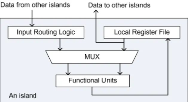
Fig. 1 The island architecture in DRFM.
level, which results in a significantly smaller constraint set. The experimental results shown later can sustain our above claims.
三、 研究方法與成果
Communication synthesis for interconnect minimization targeting distributed register-file microarchitecture
In a centralized register (CR) architecture, there exists a large aggregate register file shared by all FUs and an FU is expected to access any register within one clock cycle. However, if this assumption is still retained, the increasingly long global interconnect delay can significantly stretch the clock period as the manufacturing process keeps evolving. Therefore, the distributed register (DR) architecture is proposed to overcome this issue [11]–[24]. In a DR-based architecture, the whole system is partitioned into a set of clusters and each cluster contains its own local register file and FUs. As a result, most register accesses are kept fast within a cluster while only few accesses require long inter-cluster communication.
Several DR-based architectures are proposed in the recent literature. Regular distributed register (RDR) architectures are capable of providing accurate delay estimation for inter-cluster communication at very early design phases. The related studies focusing on behavioral synthesis as well as transfer scheduling and routing for RDR-based architectures can be found in [13]–[19]. On the other hand, the distributed register-file microarchitecture (DRFM) is first proposed in [20] to take full advantage of rich distributed embedded memory blocks as register files in modern FPGA platforms [26][27]. The island architecture in DRFM is shown in Fig. 1. An island contains input routing logic, local register file, and functional units (FUs). The local register file is used to store computation results produced by internal FUs. It is also responsible for feeding data operands to internal FUs and external FUs located in other islands. DRFM assumes that every operation can be accomplished in any island within one control step and produces exactly one
7
output. When implementing a system utilizing DRFM, [20] shows that different implementations could produce tremendously different results in terms of area and performance. Namely, how to map operations into islands needs to be handled very carefully. As well, [20] finds that the number of inter-island connections (IICs), which can properly estimate the cost of global interconnects, is highly correlated with the resultant resource usage and system performance after synthesis. Consequently, the number of IICs can be used as the metric to rate the quality of synthesis output.
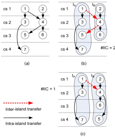
Here we reveal two key observations. First, the solution space is quite limited in [20] since the given scheduled DFG is not allowed being altered, which is also mentioned in [21]. Given a scheduled DFG as shown in Fig. 2(a), if there are two available islands (IA and IB) and the given
DFG cannot be altered, then the optimal synthesis (i.e., resource binding) result is presented in Fig. 2(b). The (operation) nodes within the same shaded region are mapped into the same island. Apparently, the solution in Fig. 2(b) needs two IICs. However, if rescheduling is allowed, a better solution can be obtained as shown in Fig. 2(c), where only one IIC is demanded. Note that the
Fig. 2 (a) The scheduled DFG, (b) the scheduled and bound DFG, and
8
total number of required control steps in the new solution remains unchanged, which means the IIC reduction does not come from a tradeoff with system performance.
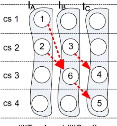
Be aware the difference between the number of inter-island connections and the number of inter-island transfers (IITs) – the former is usually less than the latter due to resource sharing. For example, in Fig. 3, those four IITs merely need three IICs (i.e., two for IA to IB and the other for IB
to IC). That is, multiple IITs can share an IIC as long as they have the same source-destination
island pair as well as different arrival times. For instance, IIT3,4 from node 3 to node 4 and IIT6,5
from node 6 to node 5 can legitimately share an IIC but IIT1,6 and IIT2,6 cannot. This suggests that
the synthesis goal in DRFM is about minimizing the number of IICs instead of IITs if saving global interconnect resource is the actual target.
Furthermore, the number of write port of a local register file is restricted to one but no restriction is put on the number of read ports in the original DRFM. However, it is not practical that the number of read ports is assumed unlimited since a register file with a large number of read ports is both slow and area-consuming. Assume that each local register file possesses only two read ports, then as shown in Fig. 4(a), access conflicts on read port occur at cstep 4 because there are three data transfers want to access the registers in island IA – the data transfer DT3,4,
Fig. 3 The scheduled and bound DFG.
Fig. 4 (a) A scheduled and bound DFG with access conflicts, and
9
DT2,7 and DT1,11. Apparently, at least one of these three read accesses has to be postponed, which consequently increases the latency of the DFG from four to five. The approach in [20] deals with this problem by data-forwarding, which adds input buffers into the input routing logic. In that approach, each data-forwarding consumes one read port and takes one cstep. However, incorporating read port restriction during scheduling and binding can minimize those read access conflicts without increasing hardware cost (i.e., input buffers). Another DFG, as shown in Fig. 4(b), demonstrates that it is possible to keep the latency still four without introducing any data access conflicts if the read port restriction is properly deliberated.
The problem formulation of this work is as follows: Given a DFG and a resource constraint (the number of islands), obtain a scheduled and bound DFG with the minimized latency as well
as minimize the number of required IICs.
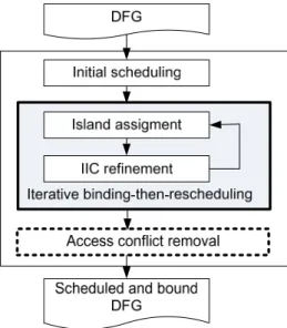
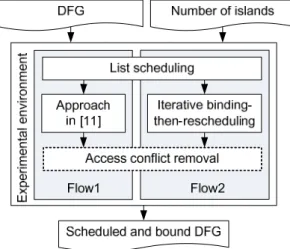
The overall flow of the proposed method is shown in Fig. 5. Given a DFG, list-scheduling is first performed to obtain an initial scheduling result and followed by the iterative cstep-by-cstep binding-then-rescheduling process. In each iteration, two operations, island assignment (binding) and IIC refinement (rescheduling), are applied consecutively. The way used for island assignment in this work is similar to the horizontal assignment adopted in [20]. Namely, island assignment is formulated as a minimum-weighted bipartite matching problem, where a weight on an edge represents the number of extra IICs induced by the corresponding matching. However, the aforementioned algorithm does not allow rescheduling and generally produces a locally optimized solution. Hence, an IIC refinement process is proposed to look for a better result from the expanded solution space via rescheduling. More details are described in Section 4.1. Meanwhile, the IIC refinement procedure is also capable of handling the read port restriction.
10
After the iterative phase, an access conflict removal process is followed to eliminate all remaining access conflicts, if any. The details are given in Section 4.2. In the very end of the proposed flow, a scheduled and bound DFG with minimized IICs is derived.
A. IIC refinement
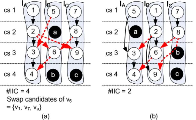
As mentioned above, the algorithm for island assignment generally leads to a locally optimized solution. However, further improvement can still be achieved by allowing certain operation rescheduling, as depicted in Fig. 2(b) and Fig. 2(c), as long as the data dependency is still intact. In this article, a special node (in black) called bubble, is inserted to explicitly indicate that the corresponding island is idle at that specific cstep. As depicted in Fig. 6(a), the two bubbles a and b suggest that IB is idle at cstep 2 and 4.
The proposed IIC refinement process is based on KL algorithm [28], which is broadly used in partitioning-related problems. Within the process, nodes and bubbles are swapped for IIC minimization. A swap can be made between two nodes or between a node and a bubble. A swap is considered feasible only on two conditions: (i) nodes must be unlocked, and (ii) data dependency must be preserved after swapping. For example, in Fig. 6(a), the feasible swap candidates for node 5 are {node 1, node 7, node a}. A feasible swap pair of node u and node/bubble v is denoted as (u, v). The gain of a swap pair is defined as how many IICs it can reduce, i.e., the difference between the numbers of IICs before and after the swap. The gain of a swap pair (u, v) is denoted as gu,v. All feasible swap pairs are collected into the feasible swap
pair set (FSPS). After performing an actual swap, FSPS and gains of swap pairs are updated accordingly. The key steps of IIC refinement are described as follows:
(i) Set all operation nodes unlocked.
Fig. 6 (a) The DFG at the beginning of the iteration, and
11
(ii) Find a swap pair with the largest gain from FSPS. (iii) Swap the pair then lock the operation node.
(iv) Update FSPS and recalculate the gains of pairs in FSPS. (v) Repeat (ii) to (iv) until FSPS is empty.
(vi) Keep the fist k swaps and undo the rest if the partial gain sum of the first k swaps is the largest and positive; go to (i).
(vii) Otherwise, terminate IIC refinement.
For example, a partially scheduled and bound DFG is shown in Fig. 6(a) with an IIC number equal to 4, where FSPS = {(1, 5), (1, 7), (2, a), (2, 8), (3, 6), (3, 9), (4, b), (4, c), (5, 7), (5, a), (6, 9), (8, a), (9, c), (9, b)}. Initially, the gains of all feasible swap pairs in FSPS are calculated as follows:
g1,5 = 0 g1,7 = –1 g2,a = –1 g2,8 = –1 g3,6 = 0 g3,9 = –2 g4,b = 0 g4,c = –1 g5,7 = –2 g5,a = 0
g6,9 = –1g8,a = –1 g9,c = 0 g9,b = 1
Then the swap pair (9, b) is selected to be swapped and node 9 is locked after the swap. The FSPS and the gains are therefore needed to be further updated accordingly. This process is not terminated until FSPS is empty. Table 1 shows the gain and the partial gain sum of the eight consecutive feasible swaps in this iteration. As a result, only the first three swaps, including (9,
b), (1, 5) and (2, a), are actually desired. The resultant DFG at the end of this iteration is
shown in Fig. 6(b) and it merely requires two IICs instead of four in Fig. 6(a).
B. Coping with read port restriction
The approach proposed in the previous section neglects the read port restriction. However, as illustrated in Fig. 4, considering the read port restriction during scheduling and binding can effectively minimize access conflicts without increasing hardware cost. Therefore, an augmented IIC refinement process is further presented in this subsection.
During IIC refinement, a secondary gain hu,v of the swap pair (u, v) is defined as the
Table 1 Gains and partial gain sums in an iteration
n-th swap 1 2 3 4 5 6 7 8 Swapped pair (9, b) (1, 5) (2, a) (5, a) (7, a) (4, c) (3, b) (6, b) Gain 1 0 1 0 –1 –1 1 –2 Partial gain sum 1 1 2 2 1 0 1 –1
12
decreased number of access conflicts once the swap takes place. The number of access conflicts of an island at a specific cstep is calculated as the difference between the number of demanded register-file accesses and the number of read ports a register-file actually owns. The corresponding equations are given as follows.
ports read # accesses demanded # conflicts # (1) v u v u v u v u ping huv and swapping after accesses demanded # and swapping before accesses demanded # and swapping after conflicts # and swap before conflicts # , (2)
The restriction on read port size of a register-file is set to two in this work. As revisiting the case shown in Fig. 4(a), the primary gain g6, 7 is zero and the secondary gain h6, 7 is one
because there is one (no) conflict at cstep 4 in island IA before (after) node swapping.
The second step of IIC refinement described in Section 4.1 is therefore modified as follows: find a swap pair with the largest primary gain from FSPS; if there are many pairs with the same largest primary gain, choose the one with the largest secondary gain. By means of exploiting the extra secondary gain for tie breaking during scheduling and binding, the read port restriction is well deliberated, and access conflicts can thus be minimized.
Finally, an access conflict removal procedure is followed after the IIC refinement process to ensure that absolutely no access conflicts are left. The procedure simply postpones any conflicted accesses that cannot be removed in the previous iterative binding-then-rescheduling process.
The proposed method has been implemented in C++/Linux environment and all experiments were conducted on a workstation with an Intel Xeon 3.2GHz CPU and 4GB RAM. For fair and
13
comprehensive comparisons, two different synthesis flows are created, as depicted in Fig. 7. Given an input DFG and a resource constraint, list scheduling is first performed to provide an initial scheduling result for both flows. Then, Flow1 implements the approach proposed in [20], while Flow2 carries out the proposed approach. The access conflict removal procedure is then conducted as a post-processing for both flows.
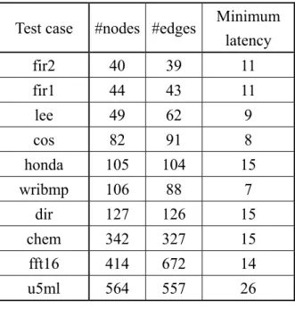
The test cases are from different benchmark sets [29]–[31], which are frequently used in high-level synthesis field. The basic information of these test cases (DFGs) is given in Table 2. The first three columns list the names, number of nodes, and number of edges, respectively. The last column reports the minimum possible latency obtained by ASAP scheduling with unlimited available resources. Two configurations are deliberated in our experiments – synthesis is performed without (with) a resource constraint in Configuration 1 (2), respectively. In Configuration 1, the number of islands is set as the minimum number that still guarantees the synthesis outcome with the minimum latency indicated in Table 2; that is, there is in fact no resource constraint at all. However, the assumption about unlimited available hardware resource is impractical in the real world. Hence, in Configuration 2, for every test case the number of available islands is reduced by half as:
2 1 Config. in islands # 2 Config. in islands # (3)
Table 3 reports the experimental results without read port restriction, which means that only the primary gain is deliberated during node swapping. The results show that the proposed Flow2 achieves on average 21.0% and 24.5% IIC reduction in Configuration 1 and 2 respectively as
Table 2 The basic information of benchmark
Test case #nodes #edges Minimum latency fir2 40 39 11 fir1 44 43 11 lee 49 62 9 cos 82 91 8 honda 105 104 15 wribmp 106 88 7 dir 127 126 15 chem 342 327 15 fft16 414 672 14 u5ml 564 557 26
14
compared with existing Flow1, which clearly demonstrate that the proposed algorithm does outperform the prior art. Table 3 also suggests that average #IIC reduction in Configuration 2 is better than that in Configuration 1. It is because the number of available islands in Configuration 2 is roughly a half of that in Configuration 1, which also reduces the total number of required IICs in Configuration 2. Therefore, the effect of eliminating an IIC is more significant in Configuration 2 than in Configuration 1.
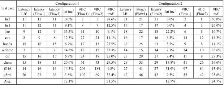
Table 4 gives the results with the read port restriction, which is set to two for all test cases. The results conclude that Flow2 achieves on average 21.5% and 24.7% IIC reduction in Configuration 1 and 2 respectively as compared with Flow1, which is pretty much the same as the results without the read port restriction. Furthermore, as stated before, the process for access conflict removal may increase the latency if there do exist non-removable access conflicts after binding-then-rescheduling. The first three columns for both configurations in Table 4 indicate the
Table 4 The experimental results with the read port restriction ( = 2 )
Test case Configuration 1 Configuration 2 Latency LB1 latency (Flow1) latency (Flow2) lat inc
2 #IIC (Flow1) #IIC (Flow2) #IIC red3 Latency LB1 latency (Flow1) latency (Flow2) lat inc
2 #IIC (Flow1) #IIC (Flow2) #IIC red3 fir2 11 11 11 0.0% 7 5 28.6% 21 21 21 0.0% 2 1 50.0% fir1 11 12 11 9.1% 8 7 12.5% 17 17 17 0.0% 4 3 25.0% lee 9 12 9 33.3% 11 10 9.1% 18 22 18 22.2% 6 5 16.7% cos 8 9 8 12.5% 27 24 11.1% 16 17 16 6.3% 14 12 14.3% honda 15 16 15 6.7% 17 13 23.5% 23 25 23 8.7% 9 8 11.1% wribmp 7 8 7 14.3% 18 12 33.3% 14 15 14 7.1% 14 10 28.6% dir 15 16 15 6.7% 24 18 25.0% 27 29 27 7.4% 11 8 27.3% chem 15 18 15 20.0% 61 43 29.5% 29 33 29 13.8% 41 26 36.6% fft16 14 16 14 14.3% 204 184 9.8% 27 41 27 51.9% 97 84 13.4% u5ml 26 27 26 3.8% 102 69 32.4% 42 46 42 9.5% 55 42 23.6% Avg. 12.1% 21.5% 12.7% 24.7%
1: Lower bound of latency; 2: Latency increase of Flow1 over Flow2; 3: #IIC reduction of Flow2 over Flow1
Table 3 The experimental results without the read port restriction
Test case
Configuration 1 Configuration 2 #island latency #IIC
(Flow1) #IIC
(Flow2) #IIC reduction #island latency
#IIC (Flow1)
#IIC
(Flow2) #IIC reduction fir2 5 11 7 5 28.6% 2 21 2 1 50.0% fir1 6 11 8 7 12.5% 3 17 4 3 25.0% lee 6 9 11 10 9.1% 3 18 6 5 16.7% cos 12 8 27 24 11.1% 6 16 14 12 14.3% honda 10 15 17 14 17.6% 5 23 9 8 11.1% wribmp 16 7 18 14 22.2% 8 14 14 10 28.6% dir 11 15 24 17 29.2% 5 27 11 8 27.3% chem 24 15 61 38 37.7% 12 29 41 28 31.7% fft16 32 14 204 180 11.8% 16 27 97 83 14.4% u5ml 29 26 102 71 30.4% 14 42 55 41 25.5% Avg. 21.0% 24.5%
15
lower bound of latency obtained from Table 3 and two resultant latencies given by two different synthesis flows. The proposed Flow 2 achieves the minimum latency for all test cases in both configurations while Flow1 increases the average latency by about 12%, which clearly demonstrates that the proposed method can handle the read port restriction very well.
As previously mentioned, the number of inter-island connections (IICs) is different from the number of inter-island transfers (IITs). In general, the number of IITs is commonly used for power estimation of on-chip communication, while the number of IICs is mostly used to estimate the cost of global interconnects. Nevertheless, during synthesis, it is not always possible to reduce both IICs and IITs at the same time; in other word, there is a tradeoff between area/performance (IIC) and power (IIT) optimization. Obviously, the synthesis algorithm proposed in this article focuses on IIC minimization.
Throughput optimization for latency-insensitive system with minimal queue insertion
Throughput optimization for LIS has been extensively discussed in recent years. Several research works are done based on different hardware architecture assumptions and different physical layout assumptions. Earlier works (before 2003) regard every LIS as an ideal system, which assumes infinite queue size and thus no back-pressure. To the best of our knowledge, Lu and Koh are the first ones who propose the method to deal with the throughout optimization of LIS with back-pressure arising from the effect of finite queue size on communication channel [32], [33]. They show a practical LIS with finite queue size can still achieve the same maximal sustainable throughput of its ideal LIS counterpart if proper queue sizing is performed. After that, Collins et al. use a marked graph to model an LIS alternatively [34], [35]. They propose a heuristic approach for queue sizing that can produce fairly good solutions with a short runtime. In addition, they also make a different assumption on hardware architecture of communication channel compared with the one used in [9], [10]. In our opinion, Collins’ assumption better fits the real-world design environment. However, their method is heuristic-based, order-dependent, and thus does not guarantee the optimality. Casu and Macchiarulo avoid queue sizing issue by scheduling the activation of IP cores, instead [36], [37]. However, one limitation is that planning a schedule needs enough knowledge about the overall system behavior, which is not necessarily available to engineers at this design stage. Bufistov et al. propose a method that combines both queue sizing and relay station insertion techniques to achieve optimal throughput [38]. However, they assume channel latency gets increased as queue size becomes large, which is not generally
16
appropriate in real design cases. Therefore, we present a throughput optimization technique with minimal queue insertion.
Latency-insensitive design (LID) is a design methodology for sophisticated system-on-chip (SoC) development. It enables post-refinement to a given synchronous system so that the refined system (i.e., LIS) can tolerate variant interconnect latency, which cannot be precisely estimated at early design stages. An LIS can be derived from an original synchronous system by encapsulating each IP core (pearl) within an automatically-synthesized interface (shell) and inserts repeaters to segment (i.e., pipeline) long interconnects. Those repeaters are referred to as relay stations (RS). In an LIS, every IP core must have stallability, meaning that it can be stalled temporarily without ruining correct functionality. Relay stations are clocked buffer queues utilized to pipeline a long interconnect so that the desired clock frequency can be achieved. After proper RS insertion, the resultant LIS will be still functionally equivalent to its original synchronous system [32], [33]. That is, if ignoring stalled (void) events in the output sequence, the rest informative (valid) events on each channel of an LIS are exactly the same with the informative events on every corresponding channel of its original counterpart.
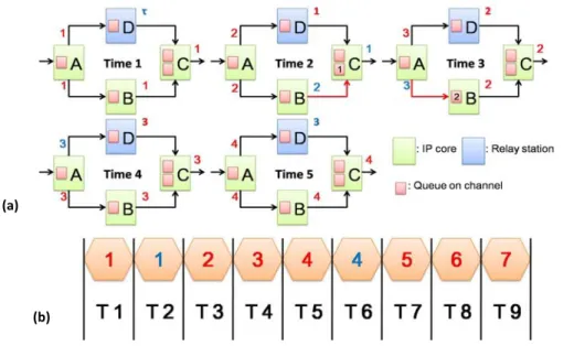
An LIS example is given in Fig. 8(a). Green rectangles represent IP cores, blue rectangles represent relay stations, a small red rectangle inside an IP core or an RS represents a queue on each input channel, a red number beside a communication channel labels a valid event, and a blue number marks a stalled event. Those numbers specify the sequential IDs of events generated by corresponding IP cores. Since an RS merely forwards its received events from input to output, it never generates any new valid events. Hence a symbol ‘τ’ is used to indicate a non-generated
(b) (a)
17
void event at every RS output initially. At timestamp 1, all IP cores produce their first valid events; while every RS just puts a τ at its output. At timestamp 2, core C receives a valid event from one of its two input channels, but core C needs both first valid events from each of its input channels for producing its own second valid event. As a result, the first valid data produced by core B is stored in the internal queue within core C and then waits. Meanwhile core C is stalled and outputs a void event. Since the queue of lower input channel of core C becomes full at the end of timestamp 2, core C must compel core B to stall at the next timestamp to avoid valid event loss due to queue overflow. This effect of finite queue size is referred to as back-pressure. The channels with back-pressure in Fig. 8(a) are colored in red. At timestamp 3, core C receives both valid events from its two input channels so that it can produce its own next valid output event; whereas core B is stalled at this timestamp due to back-pressure from core C. Fig. 8(b) depicts the output event sequence of core C. It is evident that core C produces three valid events every four timestamps. In other words, the throughput of this system is three fourth. This example explicitly confirms that even for an acyclic synchronous system, the throughput can still be less than one due to the effect of back-pressure.
Here we summarize the pros and cons of LIS. LIS is a promising approach for coping with variant and unknown latency incurred by global interconnects at early design stages. By properly encapsulating IP cores and inserting relay stations, this approach guarantees correctness of system functionality. However, this approach does not guarantee to achieve the maximal possible system throughput due to back-pressure.
Marked graph (MG) is a conventional representation for modeling concurrent operations within a system. Its simplicity makes it quite amenable for analyzing the behaviors of synchronous systems like LIS. A marked graph consists of two different types of nodes: places
(a)
(b)
18
and transitions. By definition, a place is capable of holding none or multiple tokens. On the contrary, a transition cannot hold any tokens but may fire to forward tokens on certain conditions. More detailed definitions and operations of MG can be found in [39], [40].
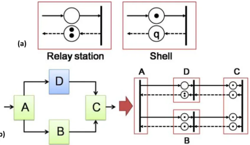
Fig. 9(a) exhibits the corresponding marked graph models of a relay station and a shell [34], a circle represents a place, a dot represents a token, a vertical bar represents a transition, and the integer q indicates the total number of tokens in that place. For an RS, the place on solid edge (indicating actual data flow) possesses no token since an RS produces a void event initially; and the place on dashed edge (indicating back-pressure flow) has two tokens because every RS contains a two-entry queue. For a shell, the place on solid edge holds one token because a shell produces a valid event initially; and the number of tokens (i.e., q) in the place on dashed edge is set to the actual queue size that the shell reserves for this specific channel [34].
Fig. 9(b) illustrates how to transform an LIS (same one as in Fig. 8) into its MG representation, assuming that the queue size of all channels in shells is set to one. Furthermore, it has been proved that the maximal sustainable throughput (MST) of an LIS is bound to the lowest token-to-place ratio (TPR) of all cycles in its corresponding MG [34], [35]. In Fig. 9(b), the most throughput-critical cycle {A, D, C, B, A} contains four places but only three tokens, so the MST of this LIS is 3/4. Fortunately, proper queue sizing at right places can increase the TPR of such critical cycles and therefore boost the overall system throughput. For example, if the queue size of core B is increased to two, then the TPR of the aforementioned cycle rises from 3/4 to 1, which achieves the optimal MST (i.e., 1) of this system. It also has been proved that MST of an acyclic synchronous system can always be boosted to one via proper queue insertion. Heuristic methods that try to minimize additional queue insertion for throughput optimization can be found in [34], [35].
Then we present our throughput optimization methodology with minimal additional queue insertion. A new representation named quantitative graph (QG) is first proposed for LIS modeling because QG is, in our opinion, more convenient for later mathematical manipulations. Then we show how to derive a constraint set from a QG so that the optimal solution with minimal queue size can be achieved through integer linear programming (ILP). Though ILP guarantees the optimality, it may fail to find a solution if the size of constraint set is too large. To overcome this problem, we further develop a polynomial-time technique to condense an original QG into a compacted one (CQG) so that a moderately large QG (i.e., a large practical LIS) can still be resolved using ILP. At last, we again present a polynomial-time approach to transform an optimal solution for a CQG back into the corresponding optimal solution for the QG counterpart.
19
A. Quantitative Graph (QG)
A quantitative graph with respect to a given MG is a quadruple (V, E, w, q), where V is the set of vertices corresponding to the transitions in that MG; E V × V is the set of edges representing the place pairs in that MG; w : E → Z* specifies the number of valid tokens for
an edge e, denoted as w(e); and q : E → Z+ indicates the queue size for an edge e, denoted as
q(e). That is, for an edge e = (v1, v2), w(e) specifies the number of tokens in the place on solid
edge from transition v1 to transition v2 and q(e) specifies the one on dashed edge from
transition v2 to transition v1 in the original MG, respectively. Fig. 10 gives an example about
the transformation from an MG to a QG.
As mentioned, the MST of a system is bound by the lowest TPR of all cycles in its MG. For a QG, the MST can also be determined in a similar way. First, identify all cycles in a QG, assuming that all edges are undirected. By doing so, every cycle C’ in an original MG can always find its counterpart cycle C in the corresponding QG. Next, a cycle C in QG is represented as a set of edges. The edges in C can be partitioned into two disjoint set F and R, where F contains the edges being traversed in its regular direction while R contains those being traversed in its revere direction. Then, for every edge e along a cycle C in QG, accumulating either w(e) or q(e) depends on whether it belongs to F or R, and the resultant value is actually equal to the number of tokens in the counterpart cycle C’ in MG. As well, the number of edges in C (i.e., |C|) is the same as the number of places in C’. Similarly, the TPR of a cycle C in QG is further defined as:
R F C e q e w C TPR e F e R
) ( ) ( ) ( (4)It becomes apparent that finding the lowest TPR of all cycles in MG is now equivalent to identifying the lowest TPR of all cycles in QG because both of them are indeed identical.
20
B. Compacted Quantitative Graph (CQG)
As described, a smaller QG is highly preferred since ILP is employed for optimization later. However, it is not trivial to derive an equivalent reduced QG whose resultant MST is still the same as that of the original QG. Therefore, here we present a technique including two operations for QG compaction while still keeping MST unaltered so that our approach can deal with large practical systems.
With respect to a QG G, a compacted quantitative graph (CQG) H is defined as a sextuple (V,
E, w, q, b, c), where (V, E, w, q) is identical to that of G; c : E → Z+ assigns an extra compaction factor regarding an edge e to record the compaction level, denoted as c(e); and b : E → Z+ specifies an extra burden factor regarding an edge e to register the load level due to
compaction, denoted as b(e). Both factors are initialized to one for all edges in CQG. Besides, the TPR of a cycle C in CQG is defined as:
C e R e F e e c e q e w C TPR ) ( ) ( ) ( ) ( (5)Since c(e) is set to one initially, the summation of c(e) along any cycle C in H is equal to |C| at the very beginning. In other words, (5) returns the same value as (4) does for any cycle C, which concludes that MST in H is identical to that in G. We further define the token-place
difference (TPD) of a cycle C in either QG or CQG as:
C F e e c e w C R e e c e q e TPDC cycle in for ), ( ) ( cycle in for ), ( ) ( ) ( (6)
Property 1: Given a cycle C in a QG representing any arbitrary acyclic synchronous
system, TPR(C) is no less than one ( 1) if and only if the summation of TPDC(e) is no less
than zero ( 0).
Path Condensation:
A simple path p = (v1, v2, …, vk) in CQG is condensable if k ≥ 3, v1 vk, id(vi) = 1 for 2 ≤ i ≤ k;
and od(vi) = 1, for 1 ≤ i ≤ k – 1; where id(vi) and od(vi) gives input degree and output degree
of vi, respectively. Then, given a CQG H, a condensable path p in H, and E(p) is the set of
edges in p, the operation path condensation derives a new CQG H’ from H by replacing p with a condensed edge ep(v1, vk), where:
21 )] ( [ min ) ( , ) ( ) ( , ) ( ) ( , ) ( ) ( ) ( ) ( ) ( ) ( e b e b e c e c e q e q e w e w p E e p p E e p p E e p p E e p
(7)Property 2: If CQG H’ is derived from CQG H by applying path condensation, then MST
in H’ is identical to that in H.
Fig. 5(a) illustrates an example of path condensation. It is apparent that the size of CQG (in terms of vertices and edges) can be effectively reduced, while MST remains unaltered for both CQGs before and after path condensation.
Edge Unification:
After applying path condensation, there may be multiple edges between two vertices in CQG, as shown in Fig. 11(a). For such pair of vertices vi and vj, Em(vi, vj) is the set containing all
parallel edges from vi to vj. An edge ed Em(vi,vj) is called a dominating edge if c(ed) – w(ed)
≥ c(ek) – w(ek) for every edge ek Em(vi,vj). Then, given a CQG H and Em(vi,vj), the
operation edge unification derives a new CQG H’ from H by removing all edges in Em(vi,vj)
except leaving one dominating edge ed and modifying b(ed) as:
) , ()
(
)
(
j i m k E v v e k db
e
e
b
(8)Property 3: Given a CQG H representing any arbitrary acyclic system, a CQG H’ derived
from H by applying edge unification, a cycle C passing through that specific dominating edge
ed, then the total queue size along C suggested by H’ with target MST of H’ = 1 is also
mandatory for any cycle C’ in H derived from C by replacing ed with other parallel edge to
ensure MST of H = 1.
The proofs of above three properties are omitted due to page limitation. Fig. 11(b) illustrates an example of edge unification, and as a result the number of edges is reduced. Moreover, after edge unification shown in Fig. 11(b), path condensation can again be applied along the path (v1, v4, v5) to further reduce the size of CQG. That is, these two operations can be
performed repeatedly until no further reduction can be made. Fig. 11(c) gives the final minimal CQG, which contains only two vertices and an edge.
22
C. ILP Formulation
After a series of path condensation and edge unification operations, a CQG H with minimal vertices and edges can be derived. Next, the issue becomes how to allocate a minimal number of queues to every edge in H while keeping MST of H still one. We resolve this issue via integer linear programming (ILP). The objective and the corresponding constraint set for ILP is formulated as follows: Minimize:
E ee
q )
(
(9) Subject to: H C e TPD C eC( )0 for every cycle in
(10) H e e c e q ew( ) ( )2 ( ) 0, for every edge in (11) It is obvious that the number of constraints generated by (10) is proportional to the number of
(a)
(c)
Fig. 11 (a) The path condensation operation. (b) The edge unification operation. (c) The
23
cycles in H, and this number can increase extremely fast even if the graph size just grows a bit. Thus, it now becomes clear that why we have to compact a given QG by all means before performing ILP. Meanwhile, since one or more cycles may be compacted into a single edge, e.g., Fig. 11(c). Thus, (11) gives the constraint for a special kind of cycle that contains only one edge, where the cycle is formed by traversing that edge in its normal (forward) direction as well as its reverse direction.
D. Recovery Phase
Once ILP produces an optimal solution for a given CQG, certain operations should follow to further derive the optimal solution for the original QG. Then, we present two operations, edge
split and path expansion, for this purpose.
Edge Split:
Assume an edge ed(wd, qd, cd) is a selected dominating edge and ek(wk, qk, ck) is ed’s removed
Fig. 12 (a) The edge split operation. (b) The path expansion operation. (c) The solution
for original QG. (b)
(a)
24
parallel edge. After applying ILP, qd is set large enough to ensure that (10) holds for every
cycle C passing through ed in reverse direction. When putting ek back to CQG, qk must also be
properly set to ensure that (10) still holds for any newly generated cycle C’ derived from C by just replacing ed with ek. It follows that (10) is guaranteed to hold for every such cycle C’ if
the following inequality can be satisfied:
qk – ck qd – cd (or qk ck + qd – cd) (12)
Therefore, minimal queue size of an edge removed by edge unification previously can be derived using (12). For example, in Fig. 12(a), queue size of the blue selected dominating edge (v1, v5) is set to 4 after ILP. After edge splitting, the minimal queue size of the lower red
non-dominating edge is set to 1 + 4 – 3 = 2 by (12).
Path Expansion:
While recovering from a condensed edge ep regarding the condensable path p, (7) ensures that
(10) automatically holds for any cycle C originally passing through ep in forward direction
and now passing through p. Hence, a path expansion operation merely has to further ensure that (10) also holds for such cycle C but in reverse direction; and this can be done if the following constraint can be satisfied:
)
(
)
(
) ( p p E ee
q
e
q
(13)In general, the way for distributing q(ep) to those edges along p is not unique. However, the
following proposed strategy must be adopted to guarantee minimal queue insertion. Let em
E(p) be the edge with lowest burden factor along a condensable path p, i.e., b(em) b(e) for
all e E(p), then q(e) of each edge e along p can be determined as:
E p e e m e p m e e e q e q e e e w e c e q m for , ) ( ) ( for ), ( ) ( 2 ) ( , ) ( (14) If there are two or more edges with lowest burden factor, pick one arbitrary. It is apparent that using (14) for queue sizing can ensure that (13) always holds. Fig. 12(b) illustrates an25
example of path expansion. At last, as shown in Fig. 12(c), edge split and path expansion can be performed repeatedly until the complete optimal solution for the original QG is obtained. At the end of this section, Fig. 13 summarizes the overall flow of our proposed method for minimal queue insertion. Unlike [34], [35], identifying strongly connected components (SCCs) is unnecessary here since the testcases are acylic.
The proposed approach has been implemented in C++/Linux environment. Since it is difficult for us to get a bunch of real-world systems, alternatively, we decide to randomly build a set of different-sized directed acyclic graphs (DAGs) as QGs for evaluation, which is similar to the approach used in the experimental setup of [35]. Furthermore, latency of every edge in a DAG (i.e., communication channel in a system) is also randomly assigned with an integer within the interval [1, L]; that is, the number of relay stations required inserting at each edge (channel) is within the range [0, L – 1]. All experiments are conducted on a workstation with an AMD 1.81GHz CPU and 2GB RAM. The package lp_solve is adopted when solving ILP [41].
Our first experiment is to verify whether the proposed compaction techniques are effective. Johnson’s algorithm [42] is applied to identify all cycles in both the original QG and the minimal CQG. The experimental results shown in Table 5 clearly indicate that the proposed technique can successfully reduce the number of vertices and edges as well as achieve a remarkable reduction of cycle count. Before compaction, the cycle count for several test cases even exceeds one million, which makes ILP virtually impossible to find a feasible solution.
In our second experiment, we compare our proposed method with Collins’ heuristic method roposed in [35]. Table 6 and Table 7 report the results with L = 3 and 16, respectively. The results show that our proposed method can achieve an average reduction of 23% and 28% in queue size
Table 5 Experimental results of cycle reduction.
Case Name Original QG Minimal CQG (V, E) #Cycles (V, E) #Cycles Testcase1 (11,15) 55 (8,11) 12 Testcase2 (17,21) 51 (13,17) 14 Testcase3 (45,61) 30540 (20,35) 10123 Testcase4 (58,76) 48590 (39,45) 10497 Testcase5 (104,121) 42435 (56,73) 19754 Testcase6 (126,172) > 1Million (77,98) 132415 Testcase7 (175,201) > 1Million (66,84) 15423 Testcase8 (297,318) > 1Million (116,142) 23862
26
for L = 3 and 16 respectively as compared to Collins’ method. The results also imply that the improvement can slightly increase as fabrication process keeps scaling (i.e., L increases). Meanwhile, our method needs about 58% more runtime than Collins’ on average. However, it should be acceptable since all test cases can be completed within 24 minutes. Table 2 also shows that ILP fails in several test cases (denoted as ‘*’) if it directly applies to QG instead of minimal CQG. The reason is obvious that the size of the constraint set is too large at QG level. It is also worth to mention that several test cases contain hundreds of vertices and edges, which positively suggests our approach is capable of handling moderately large systems in practice.
四、 結論
First of all, the number of IICs has been reported to better model the global interconnect cost and then can be considered as a major QoR evaluation metric at early design stages in DRFM. In this project, we propose a resource-constrained synthesis algorithm for IIC minimization. The iterative binding-then-rescheduling procedure is first utilized for island assignment. A better island binding result can be expected because the solution search space is significantly expanded through rescheduling. The proposed algorithm also incorporates the consideration of read port restriction into scheduling and binding procedures to minimize the potential access conflicts. A post-processing procedure is then conducted to eliminate all remaining access conflicts.
The experimental results indicate that the proposed algorithm reduces the number of IICs by 21.0% ~ 24.7% on average as compared to the prior art. While adopting the read port restriction,
Table 6 Experimental results with L=3.
L L=3 Case Name
Proposed Method Collins’ Method [12] ILP directly to QG #Queues Run- time #Queues Run- time #Queues Run- time Testcase1 20 0 20 0 20 1 Testcase2 9 0 9 0 9 0 Testcase3 51 5 80 4 51 14 Testcase4 43 14 46 13 43 44 Testcase5 29 40 78 27 29 340 Testcase6 77 867 90 542 * * Testcase7 84 32 90 23 * * Testcase8 114 73 141 47 * * Ratio 0.77 1.57 1 1 - -
27
the proposed method also outperforms the previous work by about 12% in terms of average latency. As a result, the proposed algorithm should be regarded as a better alternative while performing architectural synthesis targeting DRFM.
Furthermore, a throughput optimization technique for LIS with minimal queue size is presented. First, an LIS is transformed as a newly proposed quantitative graph; next, the size of QG can be minimized through the developed compaction operations; ILP then follows to get an exact solution of minimal queue size, which can further be converted into an optimal solution for the original LIS. The experimental results demonstrate that our algorithm can achieve an average reduction of up to 28% in queue size as compared to the prior art. Moreover, the required runtime is merely about half an hour for a system with hundreds of cores. Consequently, we believe that the proposed technique is a better alternative to resolve the issue of queue sizing for moderately large systems in practice. The proposed algorithm can only handle acyclic systems at this moment. We are currently working on developing on improved version that can deal with cyclic systems as well.
Table 7 Experimental results with L=16.
L L=16 Case Name
Proposed Method Collins’ Method [12] ILP directly to QG #Queues Run- time #Queues Run- time #Queues Run- time Testcase1 68 1 68 0 68 1 Testcase2 76 0 77 0 76 0 Testcase3 290 9 437 6 290 19 Testcase4 291 31 351 19 291 52 Testcase5 256 77 386 48 256 459 Testcase6 519 1438 793 913 * * Testcase7 673 69 753 40 * * Testcase8 641 131 1035 83 * * Ratio 0.72 1.58 1 1 - -
28
五、 參考文獻
[1] International Technology Roadmap for Semiconductors. Semiconductor Industry Association, 2007.
[2] Matzke, “Will physical scalability sabotage performance gains?” IEEE Computer, vol.20, pp. 37–39, 1997.
[3] L. P. Carloni, and A. L. Sangiovanni-Vincentelli, “Coping with latency in SOC design,” IEEE Micro, vol. 22, pp. 24–35, 2002.
[4] W. J. Dally, “Interconnect-limited VLSI architecture,” IEEE Int’l Conf. Interconnect Technology, 1999.
[5] Y. Mori, V. Moshnyaga, H. Onodera, and K. Tamaru, “A performance-driven macro-block placer for architectural evaluation of ASIC designs,” Proc. Annual IEEE Int’l ASIC Conf. and Exhibit, pp. 233–236, Sep. 1995.
[6] V. Moshnyaga and K. Tamaru, “A placement driven methodology for high-level synthesis of sub-micron ASIC’s,” Proc. Int’l Symp. Circuits and Systems, vol. 4, pp. 572–575, May 1996.
[7] P. Prabhakaran and P. Banerjee, “Parallel algorithms for simultaneous scheduling, binding and floorplanning in high-level synthesis,” Proc. of Int’l Symp. Circuits and Systems, vol. 6, pp. 372–376, May 1998.
[8] D. M. Chapiro, “Globally-asynchronous locally-synchronous systems,” Ph.D. dissertation, Stanford Univ., Stanford, CA, 1984.
[9] L. P. Carloni, K. L. McMillan, A. Saldanha, and A. L. Sangiovanni-Vincentelli, “A methodology for correct-by-construction latency insensitive design,” Proc. Int’l Conf. Computer Aided Design, pp. 309–315, 1999.
[10] J.-D. Huang, Y.-S. Huang, L. Wang, and G.-W. Lee, “Throughput-Aware Floorplanning via Dynamic Optimization on Performance-Critical Loops,” Intl. Journal of Electrical Engineering, vol. 17, no.1, pp. 33–42, Feb. 2010.
[11] Kim, J. Jung, S. Lee, J. Jeon, and K. Choi, “Behavior-to-placed RTL synthesis with performance-driven placement,” Proc. Int’l Conf. Computer Aided Design, pp. 320–325, Nov. 2001.
[12] J. Jeon, D. Kim, D. Shin, and K. Choi, “High-level synthesis under multi-cycle interconnect delay,” Proc. Asia and South Pacific Design Automation Conf., pp. 662–667, Jan. 2001. [13] J. Cong, Y. Fan, G. Han, X. Yang, and Z. Zhang, “Architecture and synthesis for on-chip
29
and Systems, vol. 23, no. 4, pp. 550–564, Apr. 2004.
[14] C.-I Chen and J.-D. Huang, “A Hierarchical Criticality-Aware Architectural Synthesis Framework for Multicycle Communication,” IEICE Trans. on Fundamentals, vol. E93-A, no. 7, pp. 1300–1308, Jul. 2010.
[15] S.-H. Huang, C.-H. Chiang, and C.-H. Cheng, “Three-dimension scheduling under multi-cycle interconnect communications,” IEICE Electronics Express, vol. 2, no. 4 pp.108–114, Feb. 2005.
[16] J. Cong, Y. Fan, and Z. Zhang, “Architecture-level synthesis for automatic interconnect pipelining,” Proc. Design Automation Conf., pp. 602–607, Jun. 2004.
[17] W.-S. Huang, Y.-R. Hong, J.-D. Huang, and Y.-S. Huang, “A multicycle communication architecture and synthesis flow for global interconnect resource sharing,” Proc. Asia and South Pacific Design Automation Conf., pp. 16–21, Jan. 2008.
[18] Y.-S. Huang, Y.-J. Hong, and J.-D. Huang, “Communication Synthesis for Interconnect Minimization in Multicycle Communication Architecture,” IEICE Trans. on Fundamentals. vol. E92-A, no. 12, pp. 3143–3150, Dec. 2009.
[19] Ohchi, N. Togawa, M. Yanagisawa, and T. Ohtsuki, “High-level synthesis algorithms with floorplaning for distributed/shared-register architectures,” Proc. Int’l Symp. VLSI Design, Automation and Test, pp. 164–167, Apr. 2008.
[20] J. Cong, Y. Fan, and J. Xu, “Simultaneous resource binding and interconnection optimization based on a distributed register-file microarchitecture,” ACM Trans. Design Automation Electronics Systems vol. 14, no. 3, pp. 1–31, May. 2009.
[21] K. Lim, Y. Kim, and T. Kim, “Interconnect and communication synthesis for distributed register-file microarchitecture,” Proc. Design Automation Conf., pp. 765–770, Jun. 2007. [22] J.-D. Huang, C.-I Chen, Y.-T. Lin, and W.-L. Hsu, “Communication synthesis for
interconnect minimization targeting distributed register-file microarchitecture,” IEICE Trans. on Fundamentals, vol. E94-A, no. 4, pp. 1151–1155, Apr. 2011.
[23] S. Gao, K. Seto, S. Komatsu, and M. Fujita, “Pipeline scheduling for array based reconfigurable architectures considering interconnect delays,” Proc. Int’l Conf. Field-Programmable Technology, pp. 137–144, Dec. 2005.
[24] Terechko, E. L. Thenaff, M. Garg, J. van Eijndhoven, and H. Corporaal, “Inter-cluster communication models for clustered VLIW processors,” Proc. Int’l Symp. High Performance Computer Architecture, 2003.International Technology Roadmap for Semiconductors. Semiconductor Industry Association, 2007.
[25] L. P. Carloni, K. L. McMillan and A. L. Sangiovanni-Vincentelli, “Theory of latency-insensitive design,” IEEE Trans. on CAD, vol. 20, no. 9, pp. 1059–1076, Sep. 2001.
30
[26] Altera website. [Online]. Available: http://www.altera.com [27] Xilinx website. [Online]. Available: http://www.xilinx.com
[28] B. Kernighan, and S. Lin, “An efficient heuristic procedure for partitioning graphs,” Bell System Technical Journal, pp. 291–307, Feb. 1970.
[29] MCAS: multicycle architectural synthesis system. [Online]. Available: http://cadlab.cs.ucla.edu/software_release/mcas/
[30] ExPRESS group. [Online]. Available:http://express.ece.ucsb.edu/
[31] T. Cormen, C. Leiserson, R. Rivest, and C. Stein, Introduction to algorithms, 2nd edition, the MIT press, 2001
[32] R. Lu and C.-K. Koh, “Performance optimization of latency insensitive systems through buffer queue sizing of communication channels,” in Proc. Intl. Conf. on Computer-Aided Design, Nov. 2003, pp. 227–231.
[33] R. Lu and C.-K. Koh, “Performance analysis of latency-insensitive system,” IEEE Trans. on CAD, vol. 25, no. 3, pp. 469–483, Mar. 2006.
[34] R. L. Collins and L. P. Carloni, “Topology-based optimization of maximal sustainable throughput in a latency-insensitive system,” in Proc. of the Design Automation Conf., 2007, pp. 410–415.
[35] R. L. Collins and L. P. Carloni, “Topology-based performance analysis and optimization of latency-insensitive systems,” IEEE Trans. on CAD, vol. 27, no. 12, pp. 2277–2290, Dec. 2008.
[36] M. R. Casu and L. Macchiarulo, “A new approach to latency insensitive design,” in Proc. of the Design Automation Conf., 2004, pp. 576–581.
[37] M. R. Casu and L. Macchiarulo, “Issues in implementing latency insensitive protocols,” in Proc. of the Design, Automation and Test in Europe Conf., 2004, pp. 1390–1391.
[38] D. Bufistov, J. Julvez, and J. Cortadella, “Performance optimization of elastic systems using buffer resizing and buffer insertion,” in Proc. Intl. Conf. on Computer-Aided Design, Nov. 2008, pp. 442–448.
[39] T. Murata, “Circuit theoretic analysis and synthesis of marked graphs,” IEEE Trans. on Circuit and Systems, vol. 24, no. 7, pp. 400–405, Jul. 1977.
[40] T. Murata, “Petri nets: Properties, analysis and applications,” Proc. of the IEEE, vol. 77, no. 4, pp. 541–580, Apr. 1989.
[41] lp_solve. http://lpsolve.sourceforge.net/5.5/
[42] D. B. Johnson, “Finding All the Elementary Circuits of a Directed Graph,” SIAM Journal on Computing, vol. 4, no. 1, pp.77–84, Mar. 1975.
31
六、 成果自評
在學術論文發表方面, 在今年度我們發表了以下國際會議期刊:
1. Che-Hua Shih, Ya-Ching Yang, Chia-Chih Yen, Juinn-Dar Huang, and Jing-Yang Jou, “FSM-Based Formal Compliance Verification of Interface Protocols,” Journal of Information Science and Engineering, vol. 26, no. 5, pp. 1601–1617, Sep. 2010.
2. Juinn-Dar Huang, Chia-I Chen, Yen-Ting Lin, and Wan-Lin Hsu, “Communication synthesis for interconnect minimization targeting distributed register-file microarchitecture,” IEICE Trans. on Fundamentals, vol. E94-A, no. 4, pp. 1151–1155, Apr. 2011.
3. Juinn-Dar Huang, Chia-I Chen, Wan-Ling Hsu, Yen-Ting Lin, and Jing-Yang Jou, “Performance-driven architectural synthesis for distributed register-file microarchitecture with inter-island delay,” IEICE Trans. on Fundamentals, to appear.
及以下國際會議論文:
1. Ya-Shih Huang and Juinn-Dar Huang, “Throughput-Driven Hierarchical Placement for Two-Dimensional Regular Multicycle Communication Architecture,” Asia Symposium on Quality Electronic Design, pp. 134–139, Aug. 2010.
2. Juinn-Dar Huang, Chia-I Chen, Wan-Ling Hsu, Yen-Ting Lin, and Jing-Yang Jou, “Inter-Island Delay Aware Communication Synthesis for Island-Based Distributed Register Architecture,” Proc. of the 16th Workshop on Synthesis and System Integration of Mixed Information Technologies, pp. 58–63, Oct. 2010.
3. Juinn-Dar Huang, Yi-Hang Chen, and Ya-Chien Ho, “Quantitative Graph-Based Minimal Queue Sizing for Throughput Optimization in Latency-Insensitive Designs,” Proc. of the 16th Workshop on Synthesis and System Integration of Mixed Information Technologies, pp. 430–435, Oct. 2010.
4. Juinn-Dar Huang, Yi-Hang Chen, and Ya-Chien Ho, “Throughput Optimization for Latency-Insensitive System with Minimal Queue Insertion,” Proc. of IEEE Asia and South Pacific Design Automation Conference, pp.585–590, Jan. 2011.
5. Juinn-Dar Huang, Yi-Hang Chen, and Wan-Hsien Lin, “Performance-Optimal Behavioral Synthesis with Degenerable Compound Functional Units,” Proc. of IEEE International Symposium on VLSI Design, Automation, and Test, pp. 337–340, Apr. 2011. (Best Paper Candidate)
32
在專利方面,通過以下國內外專利:
1. 黃俊達,林步青,李耿維,周景揚,“精細頻寬調控的仲裁器及其仲裁方法" 中華民 國專利案號 I332615,2010 年 11 月 1 日。
2. Juinn-Dar Huang and Chia-I Chen, “Dynamical sequentially-controlled low-power multiplexer device,” US 7881241 B2, Feb. 2011.
3. 黃俊達,陳嘉怡,“低功率動態序向控制多工器" 中華民國專利案號 I342670,2011 年5 月 21 日。
並有以下專利正在申請中:
1. 黃俊達、呂智宏、林步青、周景揚,“應用於查找表式 FPGA 的壓縮樹延遲最佳化”。 2. 黃俊達、王毓翔、林步青、周景揚,“可參數化管線式快速傳利葉轉換硬體產生器”。 3. 黃俊達、呂智宏、林步青、周景揚,Delay optimal compressor tree synthesis for LUT-based
FPGAs
如果和我們當初在計劃提案中的預計的目標相比較,我們自評今年度計劃的完成度相 當不錯, 尤其在學術論文發表方面更有不錯的表現。(預期目標為發表一篇國際長篇期刊和 三篇國際會議論文)