Mesoporous silica reinforced by silica nanoparticles to enhance
mechanical performance
Jen-Tsung Luo
a,∗, Hua-Chiang Wen
a, Yu-Ming Chang
a, Wen-Fa Wu
b, Chang-Pin Chou
aaDepartment of Mechanical Engineering, National Chiao Tung University, Hsinchu, Taiwan bNational Nano Device Laboratories, Hsinchu, Taiwan
Received 21 June 2006; accepted 24 September 2006 Available online 23 October 2006
Abstract
Silica nanoparticle/mesoporous silica composite films were prepared by direct mixing with mechanical stirring and thermal imidization. The structural morphology was elucidated by scanning electron microscopy and the surface of the film was imaged by atomic force microscopy. The functional groups and desorption process of the films were elucidated by Fourier transform infrared spectroscopy and thermal desorption spectroscopy. The mechanical properties were investigated using a nanoindenter system. The gel matrix and the filler are very compatible because they have similar molecular content. The composite films had a higher mechanical strength than pure porous silica film. Their strength is related to the silica nanoparticle content. The interfacial compatibility, dispersion effect, and interfacial strength also affect the mechanical strength of composite films.
©2006 Elsevier Inc. All rights reserved.
Keywords: Porous silica; Nanoparticle; Composite material; Mechanical properties
1. Introduction
Porous silica materials have attracted much attention in re-cent years owing to their low density, high chemical stability, low dielectric constant, and high thermal resistance[1,2]. Func-tional porous silica gels, such as mesoporous silica and bimodal porous silica, have been developed and studied[3,4]. However, the introduction of porosity degrades the mechanical properties of porous silica film, including its strength and elastic modu-lus, and limits the range of its applications. The potential use of inorganic materials as fillers in porous silica composites in in-dustrial and technological applications has been noted. In this investigation, a reinforcing filler, nanoscale silica particles, is employed to increase the mechanical strength of mesoporous silica material. Ceramic-like particles, such as silica nanoparti-cles, are used as inorganic fillers in the preparation of compos-ite materials by the sol–gel process [5–7] or by in situ tech-nique [8]. The silica reinforcement and porous silica matrix
* Corresponding author. Fax: +886 3 5733409.
E-mail address:oam.me90g@nctu.edu.tw(J.-T. Luo).
comprise mainly tetraethyl orthosilicate (TEOS), with which they have similar physical and chemical characteristics; they have a large inorganic surface area to have the best balance of the mechanical strength[9]. The silica filler also has some advantages, such as surface modification and thermal stabil-ity. The filler and the matrix were mixed by co-polymerization to yield composites with good dispersion. Some works have also reported the method of dispersion and demonstrated an approach to preventing the aggregation of silica nanoparticles by modifying silica surfaces. These approaches have many ap-plications when their large-scale manufacturing processes are scaled down to the nanoscale. Porous silica films are manufac-tured by the high-temperature hydrolysis of TEOS in a furnace. Therefore, during thermal processes, some silanol and siloxane groups are also formed on the surface. The silanol-dominant surface is chemically modified to yield hydrophobic character-istics and thus produce a hydrophobic surface. The hydrophobic films had not only a reduced silanol group density but also an increased specific surface area.
The mechanical properties of the composite will be ex-tensively improved as the diameter of the filler falls to the nanoscale, increasing the surface area/volume ratio. Silica 0021-9797/$ – see front matter © 2006 Elsevier Inc. All rights reserved.
in ethanol solution and stirred at 300 rpm for 1 h to facilitate adequate dispersion. The mesoporous silica sol–gel was pre-pared by adding TEOS to ethanol with HCl catalyst. Tween 80 (polyoxyethylene(20) sorbitan monooleate) serves as a mole-cular template. Ethanol and deionized water are the solvents. The gel mixture ratio of TEOS:ethanol:HCl:H2O:Tween 80 is 12:21:1.2:3.4:9.6 (by weight). The gel solution was mechani-cally stirred at room temperature. Different amounts of solvent– silica particle mixtures were added to the mesoporous silica– gel. They were ultrasonicated with water reflux for 3 h. After the homogeneous solutions had been obtained, the solutions were coated on silicon or glass substrates. Then they were soft-baked at 106◦C for 1 h and cured at 400◦C for 30 min. The mesoporous structure was formed by burning off a molecular template (Tween 80) to form air pores. Hexamethyldisilazane (HMDS)–toluene solution was adopted to replace the uncon-verted surface silanol groups as trimethylsilane groups.
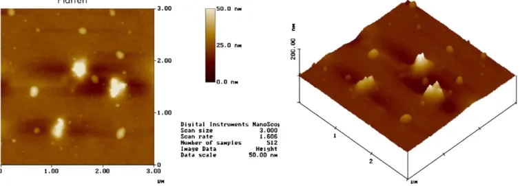
The surface modified films were then baked at 105◦C in ambient air for 3 min. SEM was utilized to characterize the mi-crostructures and interface image of the film. The roughness and the surface morphology were elucidated by AFM. The sur-face functional groups were verified by FTIR spectroscopy. The outgassing behavior and chemical desorption was examined by making TDS measurements. The refractive indices of the com-posite films were tested using an optical instrument, an N&K analyzer. The mechanical characteristics, such as the Young’s
however, some aggregate to form silica grains that are larger than the original silica particles (100 nm). The content of the filler influences the distribution of the particles [13]. If the content of the silica particle exceeds a threshold content, the aggregation of silica grain will form. The sol–gel composite solution with high silica nanoparticle content tends to produce aggregates, which will result in the residual stress in the in-terface between the filler and the matrix. Therefore, if a uni-form surface structure is intended to be obtained, then the silica nanoparticle content should not exceed that at the initiation of aggregate.
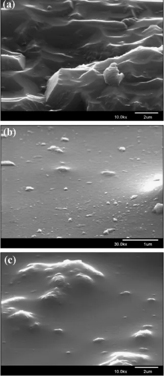
Fig. 2a shows the fracture section of SEM image. Distin-guishing silica particles from the surrounding matrix is difficult. The fracture section of the composite sample was relatively rough. A series of sheets indicated that a crack propagated some obstacles during the failure process, which can be explained by the deflection of cracks and the continual propagation of cracks on two slightly different fracture planes. A large quantity of silica particles may also result in a high degree of rough-ness.Figs. 2b and 2cshow the chemically etched and unetched surface images of the composite films, where 3 wt% silica par-ticles are dispersed in the matrix. Some of the silica parpar-ticles are well dispersed, while some formed large aggregates, dis-persed locally in the surface. Reportedly, increasing the number of hydrophobic groups on the surface of silica nanoparticle pre-vents the aggregation of silica particles[14]. The aggregation
Fig. 2. SEM image of mesoporous silica composite films: (a) fracture image, (b) chemically etched surface image, and (c) unetched surface image.
of the filler resulted in the poor mechanical properties of the composite material. The mechanical properties of the modi-fied nanocomposites are also related to the interaction across the interface. The other determinant of the agglomerates is the screwing speed. A high screw speed can break up agglomerates and create a new interface.
Fig. 3plots the Young’s modulus and hardness of the coat-ing films as functions of the silica particle content. When no silica filler is added, the surface of the film is soft, with a hardness of about 0.6 GPa, and the Young’s modulus is about 6 GPa. When the filler content is around 5%, the hardness and Young’s modulus increase to about 0.92 and 16.6 GPa,
respec-Fig. 3. Effect of silica nanoparticle content on the hardness and Young’s modu-lus of composite films.
Table 1
Refractive index and porosity of composite films with different silica particle contents
Samples Refractive index (n) Porosity (%)
As deposited 1.22 48
1% 1.25 38
3% 1.27 36
5% 1.28 35
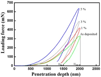
tively. The hardness and Young’s modulus increased gradually with the silica particle content. The molecular steric structure of sp3 and the volume fraction of the pore influence the me-chanical strength of a pure porous silica film. The hardness of the film increases with the sp3 content. However, increas-ing the volume fraction of the pores degraded the mechanical properties. The hardness and Young’s modulus of composite materials increased with the weight fraction of the silica parti-cles, mainly because of the dispersion effect and the interfacial strength. The effective loading transfer from the matrix to the filler is predicted when the silica particles were dispersed ef-fectively and strongly bonded with the matrix molecules. The porosities of the films, presented inTable 1, can be determined from the refractive index, according to the Lorentz–Lorenz re-lationship[15]. The addition of the silica particles reduced the porosity of the film and increased the surrounding density of the film. Hence, the hardness and Young’s modulus were in-creased. Fig. 4 plots the penetration depth and the loading curve of the composite films. The coordinate hfin is the posi-tion where the indenter was detached from the specimen sur-face. The coordinate hmaxis the position where the penetration depth of the indenter reached its maximum value. The maxi-mum loading is around 600 mN. Bolshakov and Pharr reported that all materials with an hfin/ hmax ratio of under 0.7 exhibit sin-in, while those with an hfin/ hmax ratio of over 0.7 show pile-up, because of the difference between the stress concentra-tions induced in the material during nanoindentation [16,17]. A higher silica filler content corresponds to a higher loading force.
FTIR was utilized to study the chemical interactions and bonding structures.Fig. 5shows the FTIR spectra at
wavenum-Fig. 4. Loading force vs penetration depth of composite films with different silica particles content.
Fig. 5. FTIR spectra of composite films with different silica particle content.
bers 400–4000 cm−1. The silica nanoparticles were isolated from the ethanol emulsion by the evaporation of the solvent. The main components at around 1060 to 1260 constituted the skeletal SiO2 network. The asymmetric stretching mode of the Si–O groups is at 1072 cm−1. Two peaks at 1290 and 1160 cm−1 are probably related to the splitting mode into a transverse optical/longitudinal optical (TO–LO) pair in the time domain for low-symmetry phonons that were excited from dif-ferent crystallographic faces [18,19]. The appearance of the TO–LO shoulder is related to the porosity of the samples. The shape of this band depends on the molecular structure of the silica network and evolves appreciably upon thermal conden-sation. The peak at 798 cm−1is attributable to the symmetric Si–O–Si stretching vibration and the bending mode, which is affected by the equilibrium bond angle, is present at 455 cm−1. The trimethylsilyl groups in the surface were revealed by the presence of the two absorption peaks at 1255 and 2960 cm−1. The silanol group (Si–OH) peak is at 3400 cm−1, indicating incomplete condensation in the presence of conspicuous hy-droxyl groups on the surface of the mesoporous silica films. The number of surface silanol groups can be reduced by plasma or hydrophobic modification. The presence of silica particles
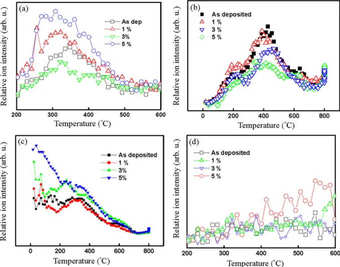
reveals an increase in the depth of penetration of oxygen mole-cules, whose diffusion behavior is like that of a free gas[20]. According to the literature, the penetration depth of O2 ex-ceeds several nanometers[21]. In this work, O2 is located in the upper atomic layer of the surface.Fig. 6b shows the CO2
(m/e= 44) desorption peak. Carbon monoxide (CO)
mole-cules were adsorbed at room temperature and oxidized to CO2. CO2decomposed at about 400◦C. The CO2molecule is bound through the carbon atom, which might be the residual organic solvent or the oxidation of CHxgroups, which are attached to the surface plane. The CO2molecules started to occupy more coordinated hollow/bridge sites. From the desorption curve, the as-deposited sample occupied the largest area while the 5% sample occupied the least area.Fig. 6c shows the outgassing behavior of H2O. Some scattered data were obtained, espe-cially at temperatures under 200◦C. The desorption intensity increased with the high silica–particle content. Below 200◦C, the desorption behavior is physical desorption. The amount of H2O desorbed reflects the water affinity of the films. The water is desorbed by the porous structure. If the porous silica sur-face loses some of its hydrophobicity, then a large amount of water will be adsorbed in the mesopores by capillary conden-sation. The amount of desorbed H2O depends on temperature and the total volume of the pores.Fig. 6d shows the decom-position behavior of methyl, which is a nonpolar group with hydrophobic properties on the surface of the film. The organic groups on the surface may come from the residual solvent and the surface modification agent. The desorption curves increased linearly with temperature.
4. Conclusions
In this study, an easy route for synthesizing a strong sil-ica/mesoporous silica composite film is achieved by combining the sol–gel and ultrasonic methods. FTIR measurements reveal that the matrix and reinforcement are chemically and physically compatible with each other. Silica nanoparticles were proven to provide greater strength and stiffness than mesoporous sil-ica material. Mechansil-ical tests indsil-icated that the loading force was transferred from the matrix to the filler, with better me-chanical results. The strength was closely related to the weight fraction of silica particles. It is also suggested that the increased strength is due to the increase of density of porous silica com-posite films.
Fig. 6. Production of thermal desorption elements as a function of temperature with different silica nanoparticle content: (a) O2(m/e= 32), (b) CO2(m/e= 44),
(c) H2O (m/e= 18), and (d) CH4(m/e= 16).
References
[1] C.T. Kresge, M.E. Leonowicz, W.J. Roth, Nature 359 (1992) 710. [2] J.S. Beck, J.C. Vartuli, J. Am. Chem. Soc. 114 (1992) 10,834. [3] Y. Fukushima, S. Inagaki, Mater. Sci. Eng. A 217 (1996) 116.
[4] Y. Zhao, J. Zou, W. Shi, L. Tang, Micropor. Mesopor. Mater. 92 (1–3) (2006) 251.
[5] H. Peng, J. Tang, L. Yang, J. Pang, Z. Yang, Y. Lu, J. Am. Chem. Soc. 128 (16) (2006) 5304.
[6] Y.Y. Yu, C.Y. Chen, W.C. Chen, Polymer 44 (2003) 593. [7] W.C. Chen, L.H. Lee, Chem. Mater. 13 (2000) 3320.
[8] K. Haraguchi, Y. Usami, K. Yamamura, S. Matsumoto, Polymer 39 (25) (1998) 6243.
[9] Y. Nakamura, M. Yamaguchi, M. Okubo, T. Matsumoto, J. Appl. Polym. Sci. 45 (1992) 1281.
[10] R. Jayaganthan, K. Mohankumar, A.A. Tay, J. Appl. Phys. 4 (2) (2005) 197.
[11] G.W. Pharr, W.C. Oliver, F. Brotzen, J. Mater. Res. 7 (3) (1992) 613. [12] W.C. Oliver, G.M. Pharr, J. Mater. Res. 7 (6) (1992) 1564. [13] S. Gopi, N. Alex, W. Darsh, J. Colloid Interface Sci. 272 (2004) 167. [14] H. Takeuchi, S. Nagira, H. Yamamoto, Y. Kawashima, Powder Technol.
141 (2004) 187.
[15] M. Born, E. Wolf, Principles of Optics, Pergamon, New York, 1983, p. 87.
[16] R. Smith, D. Christopher, S.D. Kenny, A. Richter, B. Wolf, Phys. Rev. B 67 (2003) 245405.
[17] A. Bolshakov, G.M. Pharr, J. Mater. Res. 13 (4) (1998) 1049.
[18] O.V. Misochko, M.V. Lebedev, T. Dekorsy, J. Phys. Condens. Matter. 17 (2005) 3015.
[19] F.L. Galeener, G. Lucovsky, Phys. Rev. Lett. 37 (1976) 1474. [20] S. Satoh, I. Matsuyama, K. Susa, J. Non-Cryst. Solids 190 (1995) 206. [21] J.J. Perez-Bueno, R. Ramırez-Bon, Y.V. Vorobiev, F. Espinoza-Beltranb,