行政院國家科學委員會專題研究計畫 期中進度報告
子計畫一:動態 VR 運動復健輔助系統之行為轉換與即時模
擬研究(2/3)
計畫類別: 整合型計畫 計畫編號: NSC91-2213-E-009-036- 執行期間: 91 年 08 月 01 日至 92 年 07 月 31 日 執行單位: 國立交通大學電機與控制工程學系 計畫主持人: 李祖添 計畫參與人員: 陳松雄, 游雅婷, 劉冠宏, 劉家和, 李世翔, 張富傑, 李明 橋 報告類型: 精簡報告 處理方式: 本計畫可公開查詢中 華 民 國 92 年 5 月 23 日
關鍵詞:運動模擬器,虛擬實境,加強式學習,即時模擬
Keywords: Motion Simulator, Virtual Reality, Reinforcement Learning, Real-Time Simulation 在本計畫研發的系統中,操控員透過操控界面下達指令,以操控系統中的虛擬 的運動訓練的輔助設備或載具。此操控命令將被輸入所模擬之設備或載具的精 確物理模型中,以求得真實情況下系統的反應。這些反應將透過本子計畫的行 為轉換與控制模組,而由六軸運動平台、力迴饋模組及虛擬實境顯示器表現出 來,以讓操控員獲得身歷其境的感受。這整個系統中,因為行為轉換模組的設 計扮演實際環境裡物體運動狀況以及虛擬環境中操控員身體感受之間橋樑,如 何讓操控員有身歷其境的感受,有賴於在動態模擬系統發展過程中,適當的人 (操 控員)機(動態模擬器)溝通界面及迴饋學習技術,以獲得最符合人類感覺的行為 轉換模 式。本 子計畫 只要 將相關 之運動 行為 提供給 顯示子 系統即 可。Stewart Platform 為一具有六自由度運動能力之機械平台,但其運動範圍受到其工作空間 的限制,有些動作是無法達成的,因此為了在 其有限空間下模擬出騎馬、飛機、 輪船等交通工具時之運動感覺。所以一般是以沖淡演算法(Washout Algorithm)架 構出對模擬器的力的感受。在第一年的研究中,我們探討了如下的四個課題: 了解沖淡演算法及行為轉換演算法、函數型類神經網路、訓練者修正的加強式 學習、以及模糊控制器穩定設計與探討。在第二年的研究中,我們則著重在沖 淡演算法及行為轉換演算法的探討上面。我們簡述於下。 報告內容 一、計畫概述 在本計畫研發的系統中,操控員透過操控界面下達指令,以操控系統中的 虛擬的運動訓練的輔助設備或載具。此操控命令將被輸入所模擬之設備或載具 的精確物理模型中,以求得真實情況下系統的反應。這些反應將透過本子計畫 的行為轉換與控制模組,而由六軸運動平台、力迴饋模組及虛擬實境顯示器表 現出來,以讓操控員獲得身歷其境的感受。這整個系統中,因為行為轉換模組 的設計扮演 實際環 境裡物體 運動狀 況以及虛 擬環境中操 控員身 體感受之 間橋 樑,如何讓操控員有身歷其境的感受,有賴於在動態模擬系統發展過程中,適 當的人(操控員)機(動態模擬器)溝通界面及迴饋學習技術,以獲得最符合人類 感覺的行為 轉換模 式。本子 計畫只 要將相關 之運動行為 提供給 顯示子系 統即 可。Stewart Platform 為一具有六自由度運動能力之機械平台,但其運動範圍受 到其工作空間的限制,有些動作是無法達成的,因此為了在其有限空間下模擬 出騎馬、飛機、輪船等交通工具時之運動感覺。所以一般是以沖淡演算法 (Washout Algorithm)架構出對模擬器的力的感受。在第一年的研究中,我們探討了如下的
四個課題:了解沖淡演算法及行為轉換演算法、函數型類神經網路、訓練者修 正的加強式學習、以及模糊控制器穩定設計與探討。在第二年的研究中,我們 則著重在沖淡演算法及行為轉換演算法的探討上面。我們簡述於下。
二、研究方法與成果 1. 沖淡演算法
Motion Simulation is to rebuild the feeling of passengers in a vehicle from a locally moving simulator. The most popular device utilized in motion simulation is Stewart platform. Stewart platform is a six-degree free device. Because Stewart platform is complicated and hard to design, washout filters are often used to fulfill motion simulation. The idea of washout filters is to ignore the frequency so that a limited workspace of platform can generate infinite motion. Originally, motion simulation is developed to train flight pilot. Nowadays, motion simulation not only is employed in flight simulation, but also can be used in various vehicle simulations. We design a spring device to be added after the washout filter to reduce the chance of reaching the boundary of the workspace.
The position of 6-degree free platform is defined by (x, y, z, roll, pitch, yaw). We divide it into two domains, the shift domain (x, y, z) and the angular domain (roll,
pitch, yaw). Now we construct the relationship between each two vectors in each domain respectively. We now focus on the shift domain. Figs. 1~3 are the mutual relationships of each two vectors while other variables are zero. The outer ellipses are the approximation field of the available field, and the inner ellipses are the safe zone. The fixed vector far away the origin the effective area is smaller. Hence, we can approximate the boundary of shift domain as an ellipsoid. The ellipsoid is described as 2 2 2 2 2 2 ( 1 5 ) 1 1 6 0 1 6 0 1 0 0 x y z (1) -200 -150 -100 -50 0 50 100 150 200 -250 -200 -150 -100 -50 0 50 100 150 x y z=0
Fig. 1 The mutual relation between x and y with z=0. -200 -150 -100 -50 0 50 100 150 200 -150 -100 -50 0 50 100 150 x z
Fig. 2 The mutual relation between x and z with y=0.
-250 -200 -150 -100 -50 0 50 100 150 200 250 -150 -100 -50 0 50 100 150 y z
Fig. 3 The mutual relation between y and z with x=0.
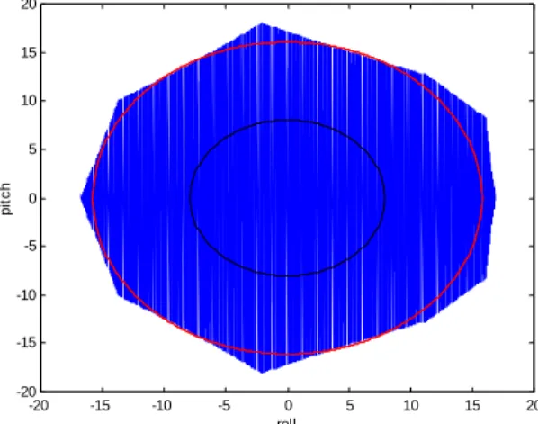
-20 -15 -10 -5 0 5 10 15 20 -20 -15 -10 -5 0 5 10 15 20 roll p it c h
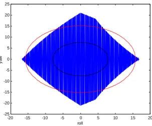
-20 -15 -10 -5 0 5 10 15 20 -25 -20 -15 -10 -5 0 5 10 15 20 25 roll y a w Fig. 5 The mutual relation between roll and yaw with pitch=0.
-20 -15 -10 -5 0 5 10 15 20 -25 -20 -15 -10 -5 0 5 10 15 20 25 pitch y a w
Fig. 6 The mutual relation between pitch and yaw with roll=0.
The mutual relationships of each vector in the angular domain are shown in Figs. 4~6 while other variables are zero. The boundary of angular domain can also be approximate as an ellipsoid, and it is described as
2 2 2
2 2 1 2
1 5 . 8 1 6 1 5 . 2
r o l l p i t c h y a w
(2) We have defined the boundary of the working space and the warning zone and
dangerous zone are described in Table 1.
Table 1 The equation of the working space surfaces.
(x, y, z) (roll, pitch, yaw)
Boundary Surface 2 2 2 2 2 2 ( 1 5 ) 1 1 6 0 1 6 0 1 0 0 x y z 22 2 2 1 22 1 5 . 8 1 6 1 5 . 2 r o l l p i t c h y a w Warning Surface 2 2 2 2 2 2 ( 1 5 ) 1 8 0 8 0 5 0 x y z 2 2 2 2 2 1 2 7 . 9 8 7 . 6 r o l l p i t c h y a w
Dangerous Surface 2 2 2 2 2 2 ( 1 5 ) 1 1 2 0 1 2 0 7 5 x y z 22 2 2 1 22 1 1 . 8 5 1 2 1 1 . 4 r o l l p i t c h y a w
We consider a continuous acceleration motion. In Figs. 7 and 8, the solid line is the original position and the dash line is the position after spring device. We can see the dash line is very similar to the solid line. Thus, the feeling of pilot on the platform is very similar even the same. From Fig. 8, we can find that while the original trajectory is closer to the working space boundary, the new generated trajectory is changed bigger. In the other words, it is harder to move the actuators while the platform is closer to the working space boundary. In Fig. 8, we also can find the three still part of the original trajectory, the new generated trajectory moves slightly toward the original. In Fig. 9, the solid line is the original length of actuators and red dash line is the length of actuators after spring device. We can see the dash line is closer to origin than the solid line obviously.
Fig. 8 The angular outputs after spring device.
Fig. 9 The length of actuators after spring device.
2、行為轉換演算法
There is another way of dealing with the motion of simulators and is referred to as the motion cue. It is often used in the so-called virtual reality emulation theaters. Because this kind of application is an off-line system, engineers can design the platform variation to generate motion cues by their experience. Because of this property, there are two major advantages for motion cue. One is that because motion cue is an off-line mapping, we can plan the whole motion to avoid the movement of actuators out of the working space. The other one is that special movements can be
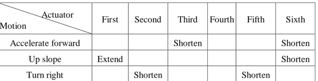
added to generate more entertaining effects. Because motion cue deeply relies on an experienced engineer to arrange a good motion cue trajectory of Stewart platform positions, we attempt to build fuzzy rules to make the motion cue design more easily. The performance of motion cue deeply depends upon the experience of the designer, and it can usually be designed delicately. The disadvantage of motion cue is that a well-designed motion cue always relies on engineers’ experience. Hence, we would like to discuss a method that engineers can plan motion cue easier even that the engineer is with less experience. Then, we focus on the trajectories of actuators. If we can find the relationships between motions and the length of actuators, we can easily design the motion cue without experience. Now we have a series of trajectory of length of actuators. We have found some relations between motions and length of actuators, and the main relations are described in table 2.
Table 2 The relations between motions and actuators.
First Second Third Fourth Fifth Sixth
Accelerate forward Shorten Shorten
Up slope Extend Shorten
Turn right Shorten Shorten
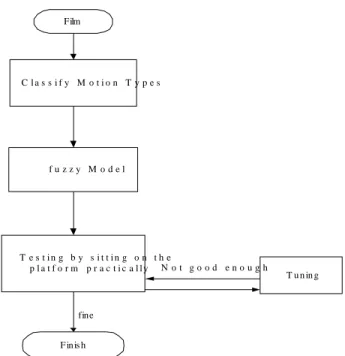
Although we have found some relations between motions and length of actuators, it is not easy to build a fuzzy rule set. It is because it is hard to understand the physical meaning that the motion cue provides. Hence, to focus on the trajectories of the length of actuators is not a good way to design motion cue. In order to satisfy the physical meaning, we then focus on the position of the platform. In this study, as shown in Fig. 10, a process is proposed to design motion cue with fuzzy rules of position of the platform. While a film is obtained, we first classify the motion, and then map different types of motions maps to different fuzzy models. Fuzzy rules are to form trajectories. Then, a pilot is to test whether the generated is realistic. If it is not good enough, the motion cue is tuned until the pilot satisfies the effects.
Actuator Motion
Film C l a s s i f y M o t i o n T y p e s T e s t i n g b y s i t t i n g o n t h e p l a t f o r m p r a c t i c a l l y F inis h fine T u n in g N o t g o o d e n o u g h f u z z y M o d e l
Fig. 10 The motion cue design process with fuzzy model. We then have the following rule tables.
Table 3 The fuzzy rules of making a turn motion. Radius of Curve Velocity Length of Curve Variation
Percentage of Y Moving Rate of Y L L L L S L L M M S L L S S S L M L M M L M M S S L M S S S L S L S S L S M S S L S S S S M L L L L M L M M M M L S M S M M L M M M M M S S
M M S S S M S L M M M S M S S M S S S S S L L L L S L M L L S L S L L S M L L L S M M L L S M S L L S S L M M S S M S S S S S S S
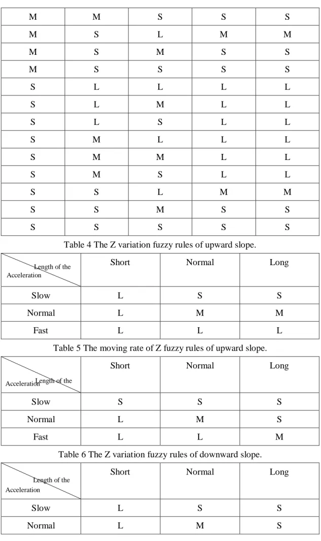
Table 4 The Z variation fuzzy rules of upward slope.
Short Normal Long
Slow L S S
Normal L M M
Fast L L L
Table 5 The moving rate of Z fuzzy rules of upward slope.
Short Normal Long
Slow S S S
Normal L M S
Fast L L M
Table 6 The Z variation fuzzy rules of downward slope.
Short Normal Long
Slow L S S Normal L M S Length of the Length of the Acceleration Acceleration Acceleration Length of the
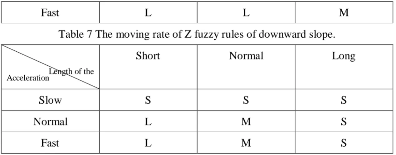
Fast L L M Table 7 The moving rate of Z fuzzy rules of downward slope.
Short Normal Long
Slow S S S
Normal L M S
Fast L M S
According to the film offered by Occam Corp., we utilized the fuzzy rules to generate the platform position. Fig 11 is the surge variation of an upward slope motion, in which the solid line is the trajectory offered by Occam Corp. and the dash line is the trajectory generated by the fuzzy rule. Fig 12 is the sway variation of an turn right motion, in which the solid line is the trajectory offered by Occam Corp. and the dash line is the trajectory generated by the fuzzy rule.
Fig 11 The Surge(Y) variation.
Fig 12 The Sway(Z) variation. 3、訓練者修正的加強式學習 在本子計畫的研究中,我們也將從事有關訓練者修正的加強式學習,主要 的兩個方向是在建模方面,另一則是 motion cue 的部分,主要的觀念乃是在虛 擬實境上,主要是要人的感受。因此當操作者對於系統有認為不好的地方,我 們希望能將這一類的感受用於修正系統,對建模部分而言,主要是對反應的不 真實性,加以修正,若是能建立這樣的系統,則針對建模部分就可以只要建一 個簡單大致的模式,而後透過加強式學習來使得模式反應更逼真,如是未來對 不同的系統開發可以不需要每一次都要找一個所要開發系統的建模專家,而只 要有一對該系統反應狀況較熟悉的人就可以了。同樣的,在 motion cue 設計的 部分,也是如此,只要一感受靈敏的人,針對系統反應的評估,即可設計出較 精準而感受逼真的動態模擬系統。 Fig. 13 加強式學習系統架構 在加強式的研究中,初步的架構如 Fig. 13上,訓練者在運動平台上,針對 平台的反應來修正而修正分為部分,其一為 Model 部分,而另一為 motion cue 部分。在做法上,我們要研究訓練者的評估在加強式學習中的效能。而系統對 訓練者其評估的不確定性,也是研究所需要析的。這是因為對同樣的狀況,在 不同的時候,由於人類感受評估的不精確性,其可能會有不同的評估值。而同 時,針對訓練者評估息的定義,也不必然和事先設定的概念一致。因此如何的 調適評估信息的歸屬函數,及其在加強式學習中的學習法則,都需要深入的探 討與研究。而目前我們加強式學習的架構是以 SONFIN 的方式來使得每一網路 的法則數不需要那麼多,可是由於 SONFIN 的學習在使用 BP 下較慢,而使用 LS 方法其所欲之輸出不知道,這些在研究中我們都將加以探討。而在內部加強 式信號的產生部分,目前我們是以傳統的 Temporal Difference (TD)預估的方式來 進行。由於最近的研究大都使用遺傳演算法,我們也會考慮使用,在未來的研 究中我們將更進一步的探討分析其結果,同時也將納入類似 washout filter 的概 念以及段落分割之學習方面。最後,由於如上二種加強式學習。在訓練者的感 受上似乎有不可分的現象。目前的概念是先分別探討與學習,以便個別系統能
正確做加強式學習,若在分析中能正確分割兩系統效應。則可據以做加強式信 號回饋的依據,若不能分割,則可考慮將二系統直接合併。由於加強式學習本 來 就 是 可 用 於 較 複 雜 , 而 不 容 易 數 學 化 的 系 統 而 當 系 統 參 數 化 後 , 其 利 用 trial-and-error 的特質,也是可以架構出加強式學習系統的。 4、即時系統之建構 本計劃所探討的是一實際操作的系統,因此即時性的操作是必要的,為了 能 有較佳的即時操作,我們提出利用外部 clock 來達到即時的概念,在傳統的 Windows 中由於其插斷其設計不佳使得其不能有即時的操作,而在較新的 NT 中其已能有好的處理能力,可是由於 HAL 及驅動程式的難撰寫,由其本身系統 中去讀取很難做到。而在我們初步的實驗中,利用外部 clock 輔以 Event 方式的 插斷處理,在其他計算程式及硬體操作干擾下,其即時精確度仍然可達360s, 如下表所示。如是的精確度是符合我們需要的。因此我們也納入此一方式來達 到在 Windows 下的即時操控的目的。 Table 8 Mode Process
Polling Event-driven Error (Event-driven) No Process 20.08ms 20.08ms 80μs 1 Process 25.68ms 20.16ms 160μs 2 Processes 25.71ms 20.24ms 240μs 12 Processes 37.7ms 20.24ms 240μs 12 Processes+存取硬碟 45.6ms 20.36ms 360μs 12 Processes+存取硬碟 + IE 上網 47.8ms 20.36ms 360μs 12 Processes+存取硬碟 + IE 上網+讀取光碟 無法 量測 20.36ms 360μs 12 Processes+存取硬碟 +play game 無法 量測 20.36ms 360μs 12 Processes+存取硬碟 +開關 IE 無法 量測 20.36ms 360μs 參考文獻
[1] C.A. Avizzano, F. Barbagkli, and M. Bergabasco, “ Washout filter design for a motocycle simulator,” Proc. Of 2000 IEEE SMC Conf., vol. 2, pp. 995-1000, 2000.
[2] M. Idan and M.A. Nahon, “ Offline comparison of classical and robust flight simulator motion control,” Journal of Guidance, Control, and Dynamics, vol. 22, no. 5, pp. 702-709, 1999.
[3] W. Wu and M. Cardullo, “Is there an optimum motion cueing algorithm? Pilot and aircraft simulators,” AIAA, Modeling and Simulation Technology Conf., 1997.
[4] M. A. Nahon and L. D. Reid, “Adaptive simulator motion software with supervisory control,” Journal of Guidance, Control, and Dynamics, vol. 15, no. 2, pp. 376-383, 1992.
[5] D. A. Panagiotopoulos, R. W. Newcomb and S. K. Singh, “Planning with a functional neural network architecture,” IEEE Trans. On Neural Networks, vol. 10, no. 1, 1999.
計畫成果自評
本研究內容與原計畫主要方向及目標君相符。部份研究內容已獲 2003 IEEE International Conference on Systems, Man, and Cybernetics 以及 2003 IEEE International Conference on Machine Learning and Cybernetics 接受,吾人將在大會宣讀論文。俟獲致更深入成果後,也將投稿至國際著名 期刊上發表。目前所獲研究成果,主要在於學理上的突破,較具學術價值。