I
行政院國家科學委員會補助專題研究計畫
■ 成 果 報 告
□期中進度報告
一個關於不使用影片分割遮罩的場景背景建立技術
與快速場景背景建立之研究
計畫類別:■ 個別型計畫 □ 整合型計畫
計畫編號:NSC 97-2221-E-009-137-
執行期間: 97 年 8 月 1 日至 98 年 7 月 31 日
計畫主持人:陳玲慧 教授
共同主持人:
計畫參與人員:
成果報告類型(依經費核定清單規定繳交):■精簡報告 □完整報告
本成果報告包括以下應繳交之附件:
□赴國外出差或研習心得報告一份
■赴大陸地區出差或研習心得報告一份
■出席國際學術會議心得報告及發表之論文各一份
□國際合作研究計畫國外研究報告書一份
處理方式:除產學合作研究計畫、提升產業技術及人才培育研究計畫、
列管計畫及下列情形者外,得立即公開查詢
□涉及專利或其他智慧財產權,□一年□二年後可公開查詢
執行單位:國立交通大學資訊科學與工程研究所
中 華 民 國 98 年 8 月 30 日
I
中文摘要
MPEG-4 採用了一種場景背景編碼技術,該方法可以提高背景部分的編碼效率。 MPEG-4 所提出的場景背景產生系統,使用算數平均將所有影像疊合以產生場景背景影 像,然而這樣的方式會使得產生出的場景背景影像中某些區域變得模糊,特別是曾經被移 動物件佔據過的位置。為了防止產生背景模糊的狀況,MPEG-4 建議使用者提供一個物件 分割遮罩,標示畫面中屬於移動物件的位置,以避免物件被混入場景背景之中。我們依照 MPEG-4 所提出的架構,建立一個場景背景產生系統。但手動產生所有畫面的物件分割遮 罩是不切實際的,而自動化影像分割方法所產生的物件分割遮罩,不可能非常完美的將所 有移動物件與背景區分。未正確區分的物件分割遮罩,會使得部分移動物件被混合入背景 影像之中。導致所產生的場景背景影像中,出現如鬼影般的移動物件殘骸。為了解決這個 問題,我們將提出一個不需要物件分割遮罩的場景背景產生系統。所提出的系統包含兩個 新方法:均勻化特徵點擷取方法與智慧型影像疊合方法。提出的特徵點擷取方法估計背景 的運動向量,利用該向量將特徵點中屬於移動物件的點予以排除。同時以均勻化的擷取方 式平均分散所有特徵點的位置。提出的智慧型影像疊合方法使用一種計數方法,使得只有 屬於背景的點被混合入場景背景影像之中。實驗結果顯示所提出的均勻化特徵點擷取方法 能有效的提高全域運動估計的準確性,因而提高場景背景影像之品質。提出的智慧型影像 疊合方法則能夠將物件排除在疊合過程以外,使得以提出之方法產生的場景背景影像,不 存在分割失誤可能導致的鬼影現象。其視覺品質接近使用人工產生之物件分割遮罩產生的 場景背景影像,並優於 Smolic et al.提出之使用自動化物件分割之場景背景產生方法。 場景背景產生系統中,應用了幾何轉換將非參考畫面轉換至參考畫面的座標系統。進 行幾何轉換會使轉換後畫面,以及根據轉換後畫面疊合的場景背景影像變的歪曲。這使得 場景背景影像所需要的儲存空間增加,同時亦限制了場景背景影像所能夠涵蓋的視角。對 此 Farin et al.提出了使用多重場景背景的方式解決問題。使用多張場景背景影像所需的儲存 空間總和,有可能較使用單一場景背景影像來的小,同時亦能涵蓋較大範圍的視角。然而 Farin et al.所提出的方法,利用暴力搜尋法找出最佳的影片分割位置。若有 N 個畫面,這樣 的方法需要 O(N3 )的執行時間與 O(N2)的儲存空間。為了降低運算的複雜度,我們提出一個 快速的多重場景背景影片分割方法。該方法包含一個可能的分割位置選取方法以及一個快 速參考畫面選擇方法。利用測量畫面之間的移動與縮放,以找出影片中有可能的分割位置。 並由這些可能的分割位置尋得最終的分割位置,將影片分割為數個子影片,最後每一個子 影片將產生一個場景背景影像。若所提出的方法找到 M 個可能的分割位置,則所提出的方 法僅需要 O(M2 N)的執行時間以及 O(M2)+O(N)的儲存空間。同時所產生的數個場景背景影 像的總儲存空間僅較暴力搜尋法所產生的略高。II
Abstract
Sprite coding adopted in MPEG-4 can increase the coding efficiency of backgrounds greatly. The averaging blending used in MPEG-4 VM’s sprite generator makes some places ever occupied by moving objects look blurring, and providing automatically segmented masks for moving objects is suggested. However, automatic segmentation can not produce perfect object segmentation masks. Segmentation faults in masks causes some moving objects being blended, and makes ghost-like shadows appear in a sprite. A sprite generation without segmentation masks is proposed. The proposed generator consists of two novel methods: a balanced feature point extraction method and an intelligent blending method. The feature point extraction method estimates the motion of background, and excludes pixels of moving objects from the feature points. Intelligent blending blends only background pixels into a sprite by a counting schema. Experiments show the feature points extracted by the proposed method increases the accuracy of global motion estimation, and the quality of generated sprites is increased. The proposed intelligent blending excludes pixels of moving objects directly in the blending procedure, and shadows caused by segmentation faults is not exist. The visual quality of our sprite is close to that using manually segmented masks and is better than that generated by Smolic et al.’s method.
Due to the geometric transformation applied in sprite coding, a sprite is distorted and its available view angles are restricted. To solve this problem, multiple sprite generation method is proposed by Farins with an exhaustive search to find the optimal partition and reference frames. Let N be the number of frames, it requires O(N3) time and O(N2) space. A fast multiple sprite partition method is proposed to reduce the complexity. The proposed method includes a fast partition point finding method and a fast reference frame finding method. The proposed partition point finding method measures translation and scaling between frames and finds candidate partition points. The final partition positions are decided from these candidate points, and reference frames of each partition are found by the proposed fast reference frame selecting method. Let M candidate partition points are found, the proposed method requires only O(M2N)
in time and O(M2)+O(N) in space. The total size of generated sprites is only slightly higher than that of Farin’s method.
報告內容
1. Introduction
MPEG-4 [1] have adopted sprite coding [2-5] to encode backgrounds belonging to a video scene into a single image. This technique achieves very low bit-rate with good reconstructed background quality. A sprite is constructed in the encoder by a sequence of complex algorithms called a ‘sprite generator’. MPEG-4 Verification Model (MPEG-4 VM) [6] has proposed a framework of a sprite generator, which is shown in Fig. 1.1. In the framework, a sprite generator consists of three parts: the global motion estimation, the frame warping and the sprite blending.
Fig. 1.1 The framework of the sprite generator in MPEG-4 VM.
The global motion estimation finds the global motion parameters (GMP) representing the spatial location variation caused by the camera motion of the background in the current frame relative to the current sprite. Then the current frame is warped (geometrically transformed) to a warped one with the same camera view as the current sprite. Finally, warped frame is blended into the current sprite by a blending strategy.
2. Project Goal and Surveys
The goal of this project is to develop a novel sprite generator and a fast multiple-sprite partition algorithm. A sprite generator is developed based on the MPEG-4’s framework, but the demand of segmentation masks is removed. Then, a fast multiple-sprite partition method is proposed. It consists of two algorithms: a video partition algorithm and a reference frame selection algorithm.
2.1 Survey on Sprite Generation
Several sprite generators have been proposed [7-13], most of them followed the MPEG-4’s framework. Smolić et al. [7] proposed a hierarchal long-term global motion estimator and a reliability-based blending strategy to generate sprite. Watanabe and Jinzenji [11] presented a sprite generator with two-passed blending and automatic foreground object extraction. Lu et al. [8-10] used a more precise segmentation method proposed by Meier and Ngan [14] to obtain moving object masks. In these methods, to avoid sprite being blurred, pixels of moving objects must be excluded from being blended into the sprite. Since manual segmentation is impractical, unsupervised segmentation methods are employed or developed in these previous sprite generators [7-13]. However, the performance of unsupervised methods can not be guaranteed and segmentation faults are always existed. These segmentation faults cause the blended sprite blur. The reliability-based blending [7] is used [7-10] to reduce the blurring. In the reliability-based
blending, a frame is divided into reliable, unreliable, and undefined regions according to the segmented masks, as Fig. 2.1 shows.
(a) (b)
Fig. 2.1. The reliability masks. (a) A segmentation mask. (b) Extracted reliability mask.
The reliable and unreliable pixels are average-blended separately, and the blended pixels with the highest reliability are chosen into the sprite. The undefined pixels do not contribute to the sprite blending. The given distance from the mask border must be large enough to cover all segmentation faults, or the generated sprite will have ghost-like shadows in some places. However, it is hard to decide the distance automatically.
2.2 Survey on Multiple Sprite Generation
The performance of a sprite generator is limited to the perspective motion model applied in the MPEG-4 VM’s framework. The perspective model projects each frame of a video sequence into a planar coordinate system, which is the coordinate system of the reference frame, as shown in Fig. 2.2. The reference imaging coordinate system for a sprite is assumed to be the first frame that is denoted as frame A. All the following frames must be projected to this reference system by geometric transformation. As the camera rotates, transformed frames are geometrically distorted, this phenomenon can be found between frame B and transformed frame B. If camera rotation continues, from Fig. 2.2, we can see that frame C can not be projected to the reference system.
Fig. 2.2 Geometric distortions using two sprites.
Massey and Bender proposed to use the middle frame of a video sequence as the reference frame [15]. The generated sprite will be much symmetric and the boundary area of the generated sprite becomes much smaller if the background of the frames in the video sequence pans toward
reference coordinate of sprite #1
frame A and transformed A on sprite #1
transformed B on sprite #2 frame B camera frame C transformed C on sprite #2 reference coordinate of sprite #2 transformed B on sprite #1
only one direction. This method only slows down the increasing effect of the sprite size, but the range of view angle is not extended.
A technique using multiple sprites was proposed by Farin et al. [16-17]. In their works, the background of a scene is stored by multiple sprites. In order to fit the MPEG-4 standard, a video sequence is divided into several subsequences, and sprites of all subsequences are generated independently. Fig. 2.2 also shows the geometric distortions using two sprites. In contrast to the geometric distortion using only one sprite shown in Fig. 2.2, the geometric distortion of frame B in sprite #2 becomes smaller. Furthermore, frame C, which is unable to be projected into sprite #1 can be projected into sprite #2 now. Full 360 degrees of camera view can be covered if more sprites are used. They have shown that using multiple sprites not only benefits the wider range of camera view angles but also reduces storage for the generated sprites. This means that storage required for multiple sprites is smaller than that for only one sprite. Farins’ method uses exhaustive search to find the optimal partition set and optimal reference frames for each partition, and this is very time-consuming.
3. Proposed Sprite Generation Method without Segmentation Masks
A sprite generator without using segmentation masks is developed. The sprite generator follows the framework of MPEG-4 VM shown in Fig. 1.1. A balanced feature point extraction method is proposed to get accurate global motion parameters. With the estimated parameters, each input frame is warped. An intelligent blending strategy is then presented to blend the warped frame to form a sprite. The details of the proposed generator are described as follows.
3.1 Balanced Feature Point Extraction Method
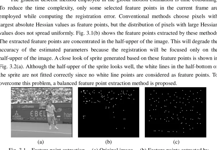
The gradient descent method employed in the global motion estimation is time consuming. To reduce the time complexity, only some selected feature points in the current frame are employed while computing the registration error. Conventional methods choose pixels with largest absolute Hessian values as feature points, but the distribution of pixels with large Hessian values does not spread uniformly. Fig. 3.1(b) shows the feature points extracted by these methods. The extracted feature points are concentrated in the half-upper of the image. This will degrade the accuracy of the estimated parameters because the registration will be focused only on the half-upper of the image. A close look of sprite generated based on these feature points is shown in Fig. 3.2(a). Although the half-upper of the sprite looks well, the white lines in the half-bottom of the sprite are not fitted correctly since no white line points are considered as feature points. To overcome this problem, a balanced feature point extraction method is proposed.
(a) (b) (c)
Fig. 3.1 Feature point extraction. (a) Original image. (b) Feature points extracted by MPEG-4 VM. (c) Feature points extracted by the proposed method.
The border area of a frame is excluded. The rest of frame is divided into non-overlapping blocks. For each block, the gray value variance is calculated to test its homogeneity. The homogeneous blocks are discarded, and feature points are extracted in the non-homogeneous blocks only.
Suppose that we want to extract N feature points from K non-homogenous blocks, N/K pixels with largest absolute Hessian values are chosen in each non-homogeneous block. Feature points extracted from Fig. 3.1(a) using the proposed method are shown in Fig. 3.1(c). In contrast to the result of using the MPEG-4’s method shown in Fig. 3.1(b), the distribution of feature points using the proposed method is more balanced. Several points on the white line in the half-bottom of the frame are extracted as feature points, this will make the white line registered well and will significantly improve the visual quality of the generated sprite.
However, from Fig. 3.1(c), we also find some points on the player located. These points should be removed according to the information in segmentation masks, but we do not want to have masks in our system. These points reduce the accuracy of estimated GMPs.
Since the motions of moving objects usually differ from the motion of background, this provides us a clue to remove these outliers. Traditional translation-based motion estimation is applied on each feature point to find the motion vector relative to the previous frame. In order to reduce the searching time, a global translation is found based on some selected feature points first, then a full search around the global translation for each feature point is preformed. First, the global translation is found by the most occurrence motion vector of 100 pixels with the largest absolute Hessian values in the feature points found previously. Then motion vector of each feature point is compared with the global translation. Feature points with motion vector differ from the global translation is classified as moving objects and is discarded from the feature points. Fig. 3.2(a) illustrates the object pixels found from the feature points shown in Fig. 3.1(c). The feature points on the player are detected successfully. These object pixels are removed from the original feature points and the final feature points are shown in Fig. 3.2(b).
(a) (b)
Fig. 3.2 Outlier removing. (a) Detected object pixels in Fig. 3.1(c). (b) The feature points after removing outliers from Fig. 3.1(c).
Figs. 3.3(a) and (b) show a close view of sprites generated using the MPEG-4 VM’s method and proposed balanced feature point extraction method, respectively. The same number of feature points is used in both methods. From the figures, we can see that those white lines in the sprite generated by the proposed method are registered very well. While the same place in sprite generated by conventional method looks blurred. The proposed method achieves much better visual quality.
(a) (b)
Fig. 3.3 Close view of sprites generated using different feature points with the same number. (a) MPEG-4 VM’s method. (b) The proposed method.
3.2 Intelligent Blending
The precision of segmentation mask affects the quality of the generated sprite. Although the unreliable region around segmentation mask boundary reduces the segmentation error in the reliability-based blending, some errors still can not be covered. The uncovered segmentation faults leave ghostlike shadows in a generated sprite, as Fig. 3.4 shows. In Figs. 3.4(a) and (b), we can see that the left foot of the player in both frames is not completely segmented. These leave some shadows after blending as shown in Fig. 3.4(c).
(a) (b) (c) Fig. 3.4 Ghostlike shadows. (a) Frames A with segmentation faults.
(b) Frame B with segmentation faults. (c) Sprite blended with segmentation faults in (a) and (b).
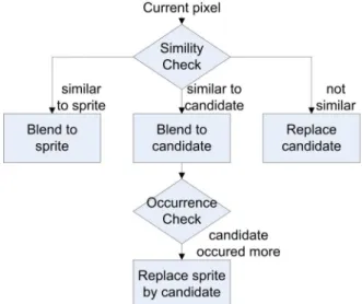
The proposed intelligent blending strategy is based on a fact that for a series of pixels in video frames corresponding to the same location of a sprite, most of these pixels will be background; only few pixels are moving objects. Since objects are moving, those object pixels will come from different positions of an object, or even different objects, their intensities will have larger variation. On the contrary, intensities of those background pixels standing for the same background point in the real world should be similar, and can be found out by counting their occurrence. Fig. 3.5 shows the flowchart of the proposed intelligent blending schema.
Let X be the incoming pixel, S be the current sprite pixel. A candidate pixel C is used to store a candidate of incoming background pixel. Two counters CS and CC are used to store the number
of pixels being blended into S and C, respectively. Initially, S and C are undefined and both counters are set as zero. A similarity check is performed on the incoming pixel by calculating two absolute differences: C X D S X D C S − = − = . (3.1)
Fig. 3.5 Flowchart of the intelligent blending.
In the starting of the blending, since S is undefined, it is set to be gray value of the first incoming pixel and CS is set to one. After filling S, the similarity check is conducted. If an
incoming pixel is unlike S (i.e. DS is greater than a preset threshold T) and C is undefined, C is set
to the gray value of the incoming pixel and CC is set to one; otherwise, if DS is smaller than T and
DC, the incoming pixel is considered as a background pixel and is blended into S, CS is increased
by 1. If DC is smaller than T and DS, the incoming pixel is blended into the candidate C, CC is
increased by 1. Two counters are compared when a pixel is blended into the candidate C. If the candidate counter is larger than the sprite counter, the sprite and the sprite counter are replaced by the candidate and the candidate counter. Then the candidate and its counter are reset to undefined and zero, respectively. This replacement is based on the fact that being described before. Since the candidate appears more frequently than the current sprite, the candidate is more likely to be the background.
If both DS and DC are larger than T, the candidate is replaced by the incoming pixel, and the
candidate counter is set to one. With a series of incoming object pixels, the candidate is continuously replaced by the incoming pixels until a background pixel is replaced into the candidate. If the background pixels appear continuously, the accumulation of candidate counter will begin.
Blending results using the Smolic et al.’s reliability-based blending and proposed intelligent blender are shown in Fig. 3.6. We can see that the ghostlike shadows are eliminated and the sprite is still clear and sharp.
(a) (b)
Fig. 3.6 Generated sprite using different blending methods. (a) Smolic’s reliability blending. (b) The proposed method.
3.3 Results and Discussions
The proposed sprite generation is built with the proposed balanced feature points and the intelligent blending. Comparisons with other methods are made both in PSNR and visual quality.
Backgrounds are reconstructed from the generated sprites and their PSNRs are calculated. The qualities of generated sprites are measured by computing the averaging PSNR of the reconstructed backgrounds. The comparison in PSNR is illustrated in Fig. 3.7. While calculating the PSNR of a frame, only the background parts in the frame are attending the calculation because the sprite contains only the information of backgrounds in a video sequence. Manually segmented masks are used to exclude moving objects in frames.
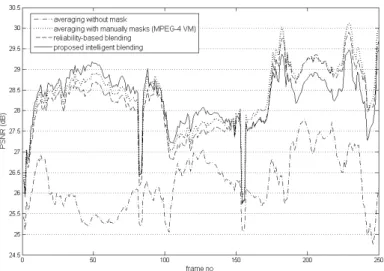
Fig. 3.7 PSNR comparison of different blending strategies.
The results of the average blending with and without manually segmented masks are plotted in dash-dotted and dotted line respectively in Fig. 3.10. The result without masks is degraded by the shadows of moving objects and the frame borders, and has low average PSNR of 26.23dB. With manually segmented masks, the averaging blending shows superior results not only in the visual quality but also in the measured PSNR. The average PSNR is 28.38dB and is the best result in our tests.
The reliability-based and intelligent blending strategies are plotted in dashed line, and normal line respectively. The reliability-based blending has average PSNRs 28.20dB. The proposed intelligent blending has average PSNRs 28.29dB, which is slightly higher than that of reliability-based blending and close to that of the average blending with perfect masks. These experiments show that the proposed method can generate high visual quality sprite without needing any segmentation mask.
Comparisons in visual quality with Lu et al.’s method [10] are shown in Fig. 3.8. Fig. 3.8 shows close views of two parts from the generated sprites. From part A shown in Figs. 3.8(a) and (b), we can see that the Lu’s sprite skews seriously but ours is not. Part B in Figs. 3.8(c) and (d) shows that the white lines in the proposed method are registered well. The average PSNR of Lu’s sprite is 23.1dB, which is much lower than that of the proposed generator (28.29dB).
(a) (b)
(c) (d)
Fig. 3.8 Close views of the generated sprites. (a) Part A by Lu et al. (b) Part A by the proposed method. (c) Part B by Lu et al. (d) Part B by the proposed method.
4. Proposed Fast Multiple Sprite Generation Method
In this section, a fast multiple-sprite partition method is proposed. The proposed method reduces the searching time for finding an applicable partition for multiple sprite generation, and the memory required during the searching is also decreased in contrast to the optimal partition method. It consists of two algorithms: video partition algorithm and a reference frame selection algorithm. The video partition algorithm is developed based on the characteristics of frame translations and scaling. Since the geometric distortion depends on the accumulated global translation relative to the reference frame, the accumulated global translation provides a good measurement on the distortion. The effect of frame scaling caused by camera zoom-in or zoom-out can be employed in a similar way. A reference frame selection algorithm is developed based on the idea of Messey and Bender’s work. In their work, the middle frame of a video sequence is suggested as the reference frame, since its background has higher possibility to be located at the center of a generated sprite. The proposed algorithm extends this idea by taking the frame with its background most likely being at the center of the corresponding sprite as the reference frame.
4.1 Proposed Feasible Partition Points Selecting Method
Two types of feasible partition points, translation-based and scaling-based, are found in this section. These points are possible partition points of the video, and the proper partition points are decided later in Section 4.3.
4.1.1 Translation-based Feasible Partition Points
The geometric projection distortion comes from the camera rotation. Farins’ experiments [16] show that the sprite area grows exponentially as camera pan angle increases. Thus the selecting of partition frames must be highly related to the effect of camera rotation. In order to capture the
effect of camera rotation, the global translations between video frames are calculated.
First, the global translation between two adjacent frames is calculated by averaging the background displacements of four corner points:
∑
∈ = } , , , { 4 1 RB LB RT LT P P ji d t v v , (4.1) where dP vis the displacement of a pixel p. LT, RT, LB, and RB denote the left-top, right-top, left bottom, and right bottom pixel. i and j are indices of two adjacent frames. Then the global translations between any two frames are calculated by a recursive procedure:
) 1 ( ) 1 ( − + − = j i j j ji a t av v v , (4.2) where avii is defined to be (0,0).
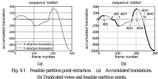
The accumulated translations are illustrated in Fig. 4.1(a). The camera pans to the right from the first frame to frame 29, then pans to the left until frame 107. When the camera begins the left-panning, the backgrounds of frames from 29 to 69 are going back through an area that has been recorded into the current sprite. Since the background area already exists in the sprite, merging these frames into the sprite will not expand the sprite area. Thus, frames from 29 to 69 must not be selected as candidate partition points, and frames 70 to 107 are considered as candidate partition points.
Now, the camera pans to the right from frame 107 to 204, and backgrounds of frames from 107 to 183 have been recorded, thus they will not be considered as candidate partition points. By similar reasons, frames 204 to 244 are not considered as candidate partition points, and frames after 245 are considered as candidates. The candidates of partition points are illustrated in Fig. 4.1(b). 0 100 200 300 -1000 -800 -600 -400 -200 0 200 400 frame number a cc u m u la te d t ran s la ti on sequence 'stefan' X-direction translation Y-direction translation 0 100 200 300 -1000 -800 -600 -400 -200 0 200 400 frame number a cc u m u la te d t ran s la ti on sequence 'stefan' #29 #107 #204 #183 #242 #245 #70 (a) (b)
Fig. 4.1 Feasible partition point extraction. (a) Accumulated translations. (b) Duplicated views and feasible partition points.
The candidates of partition points can be grouped into several pieces, and each piece covers a small range of view angles. Since the covered view angle range in a piece is small, frames in the same piece should be merged into a sprite. The first frame in each piece is considered as a feasible partition point. If the candidates are grouped into K pieces, there will be (K-1) feasible partition points. This will produce 2K-1 combinations of possible partitions. In Fig. 4.1(b), feasible partition points are frame 70, 183, and 245.
feasible partition points (x-axis and y-axis) are found. The final feasible partition points are the union of the x- and y-axis partition points (FPX and FPY).
4.1.2 Scaling-based Feasible Partition Points
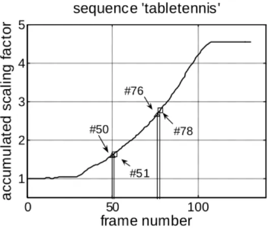
The scaling is calculated in a similar way as the translations. Each frame is geometrically transformed to its previous frame and the area of transformed frame is calculated. The scaling factor is calculated by dividing the area of transformed frame to the area of its previous frame. Then the accumulated scaling is calculated by similar recursive procedure:
) 1 ( ) 1 ( 1 ) 1 ( − − + = − × = =
∏
j i j j j i k k k ji s as s as , (4.3)where sj(j−1) is the scaling factor of frame j versus frame j-1. The accumulated scaling factors are illustrated in Fig. 4.2.
0 50 100 1 2 3 4 5 frame number a cc u m u la te d sc a li n g f a c tor sequence 'tabletennis' #50 #76 #51 #78
Fig. 4.2 Accumulated scaling factors of ‘tabletennis’.
The quality degradation of a reconstructed frame is higher as the scaling between the frame and its reference frame increases. Therefore, the accumulated scaling of frames in a single sprite is limited by the ratio of the maximum and minimum accumulated scaling factors of frames in a sprite generated from frame k to frame h. That is,
{
}
{
as k i h}
t h i k as ik i ik i < ≤ < ≤ < | min | max , (4.4)where t is a threshold. We process frames in a video sequence sequentially. When Eq. (4.4) is not satisfied at a certain frame h, frame h is considered as a feasible partition point. We keep processing the remaining frames with frame h as the starting frame to find all feasible partition points based on Eq. (4.4).
The fixed threshold t in Eq. (4.9) has a disadvantage: the scaling ratio of the last partition will be smaller than that of the other ones. In the other words, the last partition covers less scaling range than others. This can be solved by applying an adjusted threshold
{
}
L i
i as i N
t′= max 1 |1≤ ≤ , (4.5)
where L is the number of feasible partition points found based on Eq. (4.4) and threshold t, and N is the number of frames in the video sequence. The feasible partition points, FPS, based on the accumulated scaling factors are searched again by recalculating Eq. (4.4) with the adjusted
threshold t’.
4.2 Proposed Reference Frame Finding Method
The second goal of a multi-sprite partition algorithm is to find a good reference frame for each partitioned sub-sequence. In order to cover larger view angle from both directions of panning, the frame with its view at the center of the view in the subsequence would be a good reference frame. Massey and Bender suggested using the middle frame in a sequence as the reference frame, but the middle frame is not always at the center of view in a sequence. Here, we provide a method to get the reference frame with view near center.
When a sub-sequence is partitioned, its maximum and minimum values of x-axis accumulated translations can be found. The maximum value represents the right view boundary, and the minimum value represents the left view boundary. The mean of the maximum and the minimum values will represent the view center, and the frame with accumulated translation closest to the mean value is selected as the reference frame.
4.3 The Complete Algorithm
The proposed multi-sprite partition algorithm is based on the methods described in Sections 4.1 and 4.2. First, the accumulated translations and accumulated scaling factors are calculated and the feasible partition points based on accumulated translations and accumulated scaling factors are found separately. Then all feasible partition points based on translation and scaling are considered as candidate partition points. After finding the candidate partition points, the reference frames of all possible partitions are found. Based on these candidate partition points and reference frames, an exhaustive search is performed similar to Farin et al.’s method.
4.4 Results and Discussions
Identical global motion parameters of testing sequences should be used in all competitive methods to show the performance. Table 4.1 and Table 4.2 show the results of sequence ‘stefan’ and ‘tabletennis’, respectively. In both tables, we can see that Farins’ optimal method achieves excellent performance. The total sprite sizes of all sequences by the optimal method are superior to the sizes of using a single sprite. The performance of using multiple sprites is obvious, but the execution time of the optimal method is very slow.
The proposed method divides the sequence ‘stefan’ into two partitions and divides the sequence ‘tabletennis’ into three partitions. The total sprite sizes using the proposed method are only 1.41% and 6.97% higher than those using the optimal method, but the executing time of the proposed method are greatly reduced from 780 seconds to 4.1 seconds, and 95 seconds to 2.7 seconds.
Table 4.1 Experimental results of sequence ‘stefan’.
Partitions (reference frames) Total sprite size (bytes)
Executing time (seconds) Using a single sprite
(frame 1~250) - 2,862,240 -
Farin et al.’s optimal method 1-242 (57), 243-300 (265) 766,350 780 Proposed method 1-244 (53), 245-300 (265) 793,529 4.1
Table 4.2 Experimental results of sequence ‘tabletennis’.
Partitions (reference frames) Total sprite size (bytes)
Executing time (seconds)
Using a single sprite - 620,044 -
Farin et al.’s optimal method 1-49 (48), 50-75 (52), 76-131 (76) 177,766 95 Proposed method 1-51 (4), 52-77 (52), 78-131 (78) 220,964 2.7
4.5 Complexity Analysis
Complexity can be discussed in two different ways: time and space. Both complexities of the proposed and optimal method are discussed.
The complexity of Farins’ optimal method is divided into two parts: the building of coding cost matrix and the optimal partition algorithm. While building the cost matrix, the coding cost of all sub-sequences beginning at frame i and ending at frame k with reference frame r must be computed. Suppose that the sequence has N frames, the time and space complexity of building a cost matrix will be N3. However, they had developed a method to reduce the space required to N2. The optimal partition algorithm finding the best partition frame-by-frame takes N2 time.
The proposed method calculates the accumulated translation and scaling first, and both of them take linear time. The finding of candidate partition points is also linear time because it only observes the changes of accumulated translation and scaling once. Let M be the number of candidate partition points found, finding reference frame for all possible sub-sequences takes
M2N time. Finally, the Farins’ optimal partition is applied. Since only M candidate partition points
are involved, it takes only M2 time. The accumulated translations and scalings must be hold in memory and the coding-cost matrix must be generated. These will need 2N+M2 space.
Table 4.3 shows the complexity of both methods. Since M is usually very small in contrast to
N in practical, for example, M=9 and N=300 in the sequence ‘stefan’, this makes the complexity
of the proposed method better than the optimal method.
Table 4.3 Complexity comparison.
Time Space Farin et al.’s optimal method O(N3) O(N2)
參考文獻
[1] ISO/IEC MPEG Video Group, “MPEG-4 video international standard with amd. 1,” ISO/IEC 14496-2, Jul. 2000.
[2] F. Dufaux and F. Moschieni, “Background mosaicking for low bit rate coding,” Proc. IEEE Int. Conf. Image Processing, vol. 1, pp.673-676, Sep. 1996.
[3] M. Irani and P. Anandan, ”Video indexing based on mosaic representations,” Proc. IEEE, 16(5), pp. 905-921, May 1998.
[4] R. Szeliski, “Video mosaics for virtual environments,” IEEE Computer Graphics and Applications, 16(2), pp. 22-30, Mar. 1996.
[5] R. Szeliski and H. Y. Shum, “Creating full view panoramic mosaics and environment maps,” Proc. ACM Conf. SIGGRAPH 97, pp. 251-258, Aug. 1997.
[6] ISO/IEC MPEG Video Group, “MPEG-4 video verification model version 18.0,” N3908, Jan. 2001.
[7] A. Smolić, T. Sikora, and J-R. Ohm, “Long-term global motion estimation and its application for sprite coding, content description, and segmentation,” IEEE Trans. Circuits and system for video technology, vol. 9, pp. 1227-1242, Dec. 1999.
[8] Y. Lu, W. Gao, and F.Wu, “Fast and robust sprite generation for MPEG-4 video coding,” Proc. IEEE Pacific-Rim Conf. Multimedia, Beijing, China, pp. 118-125, Oct. 2001.
[9] Y. Lu, W. Gao, and F. Wu, “Sprite generation for frame-based video coding,” Proc. IEEE Int. Conf. Image Processing, vol. 3, Thessaloniki, Greece, pp. 473-476, Oct. 2001.
[10] Y. Lu, W. Gao, and F. Wu, “Efficient background video coding with static sprite generation and arbitrary-shape spatial prediction techniques,” IEEE Trans. Circuits and Systems for Video Technology, vol. 13, no. 5, pp. 394-405, May, 2003.
[11] H. Watanabe and K. Jinzenji, “Sprite Coding in Object-based Video Coding Standard: MPEG-4,” World Multiconference on Systemics, Cybernetics and Informatics (SCI) 2001, Proc. Vol.XIII, pp.420-425, Jul. 2001.
[12] H.K. Cheung and W.C. Siu, “Robust Global Motion Estimation and Novel Updating Strategy for Sprite Generation,” Vol.1, Issue 1, IET Image Processing, pp.13-20, March 2007, UK.
[13] M. Kunter, A. Krutz, M. Droese, M. Frater, and T. Sikora, “Object-based Multiple Sprite Coding of unsegmented Videos using H.264/AVC,”, IEEE 14th International Conference on Image Processing (ICIP'07), San Antonio, Texas, USA, pp. 16-19. Sep., 2007.
[14] T. Meier and K. N. Ngan, “Video segmentation for content-based coding,” IEEE Trans. Circuits and Systems for Video Technology, vol. 9, no. 8, Dec. 1999.
[15] M. Massey and W. Bender, “Salient stills: Process and practice,” IBM Systems Journal 35(3 & 4), 1996.
[16] D. Farin, P. With, W. Effelsberg, “Minimizing MPEG-4 Sprite Coding-Cost Using Multi-Sprites,” SPIE Visual Communications and Image Processing, Vol. 5308, pp. 234-245, Jan. 2004.
[17] D. Farin, P. With, W. Effelsberg, “Enabling Arbitrary Rotational Camera Motion Using Multisprites With Minimum Coding Cost,” IEEE Trans. Circuit & System for Video
Technology, vol. 16, no. 4, pp. 492-506, Apr. 2006.
已發表論文
(1) I.S. Kuo and L.H. Chen, “A High Visual Quality Sprite Generator using Intelligent Blending without Segmentation Masks,” International Journal of Pattern Recognition and Artificial Intelligence, vol. 20, no. 8, Dec. 2006, pp. 1139–1158.
(2) I.S. Kuo and L.H. Chen, “A Fast Multi-Sprite Generator with Near-Optimum Coding Bit-Rate,” International Journal of Pattern Recognition and Artificial Intelligence, vol. 23, no. 2, Apr. 2009, pp. 331-353.
計畫成果自評
本計畫的執行進度符合當初所提之計畫內容,亦完成計畫書所擬定之研究目標。在這 一年當中,首先我們提出了一個無需物件切割遮罩之場景背景產生系統。該系統包含一個 平衡式特徵點選取方法,以及一個創新的智慧型混和法。接著我們提出了一個快速多重場 景背景切割演算法,利用畫面間的位移(translation)以及放大率(scaling factor)之資訊,快速 切割影片。 本計畫之研究成果,已有兩篇論文發表於國外期刊。可供推廣之研發成果資料表
□ 可申請專利 □ 可技術移轉 日期:98 年 8 月 30 日國科會補助計畫
計畫名稱:一個關於不使用影片分割遮罩的場景背景建立技術與快 速場景背景建立之研究 計畫主持人:陳玲慧 教授 計畫編號:NSC 97-2221-E-009-137- 學門領域:影像處理技術/創作名稱
無需物件分割遮罩之場景背景產生系統發明人/創作人
陳玲慧 中文:我們將提出一個不需要物件分割遮罩的場景背景產生系統。 所提出的系統包含兩個新方法:均勻化特徵點擷取方法與智慧型影 像疊合方法。兩個方法均能夠自動排除物件對場景背景的影像,並 有效的產生高品質場景背景。技術說明
英文:A sprite generation without segmentation masks is proposed in this project. The proposed sprite generator consists of two novel methods: a balanced feature point extraction method and an intelligent blending method. The two proposed methods exclude the moving objects automatically from the generated sprite. The system achieves high visual quality sprites.
可利用之產業
及
可開發之產品
MPEG-4 編碼軟體、硬體,硬體編碼晶片製作。技術特點
1. 平衡式的特徵點選取系統能夠較均勻的抽取畫面中的特徵點, 並提高所產生之全域運動向量(global motion vector)之精確度。 2. 智慧型影像疊合系統,利用簡單的計數方式,避免移動物件被 混合入場景背景當中。推廣及運用的價值
本技術不需要物件分割遮罩亦可產生場景背景。同時亦可提高產生 之場景背景的視覺品質。 ※ 1.每項研發成果請填寫一式二份,一份隨成果報告送繳本會,一份送 貴單位研 發成果推廣單位(如技術移轉中心)。 ※ 2.本項研發成果若尚未申請專利,請勿揭露可申請專利之主要內容。 ※ 3.本表若不敷使用,請自行影印使用。可供推廣之研發成果資料表
□ 可申請專利 □ 可技術移轉 日期:98 年 8 月 30 日國科會補助計畫
計畫名稱:一個關於不使用影片分割遮罩的場景背景建立技術與快 速場景背景建立之研究 計畫主持人:陳玲慧 教授 計畫編號:NSC 97-2221-E-009-137- 學門領域:影像處理技術/創作名稱
快速多重場景背景切割演算法發明人/創作人
陳玲慧 中文:我們提出一個快速的多重場景背景影片分割方法。該方法包 含一個可能的分割位置選取方法以及一個快速參考畫面選擇方 法。利用測量畫面之間的移動與縮放,以找出影片中有可能的分割 位置。並由這些可能的分割位置尋得最終的分割位置,將影片分割 為數個子影片,最後每一個子影片將產生一個場景背景影像。技術說明
英文:A fast multiple sprite partition method is proposed. The proposed method includes a fast partition point finding method and a fast reference frame finding method. The proposed partition point finding method measures translation and scaling between frames and finds candidate partition points by the measured values. The final partition positions are decided from these candidate points, and reference frames of each partition are found by the proposed fast reference frame selecting method.