國立交通大學
工學院聲音與音樂創意科技碩士學位學程
碩士論文
以非諧音數位波導為基礎之中國編鐘聲音合成模型
Sound Synthesis Model of Chinese Chime-Bells Based
on Inharmonic Digital Waveguides
研 究 生:吳致暐
指導教授:黃志方 教授
成維華 教授
中華民國一百零一年九月
以非諧音數位波導為基礎之中國編鐘聲音合成模型
SOUND SYNTHESIS MODEL OF CHINESE CHIME-BELLS
BASED ON INHARMONIC DIGITAL WAVEGUIDES
研 究 生:吳致暐 Student: Chih-Wei Wu 指導教授:黃志方 Advisor: Chih-Fang Huang 成維華 Wei-Hua Chieng
國 立 交 通 大 學
工學院聲音與音樂創意科技碩士學位學程
碩 士 論 文
A ThesisSubmitted to Master Program of Sound and Music Innovative Techonologies College of Engineering
National Chiao Tung University in partial Fulfillment of the Requirements
for the Degree of Master in
Engineering September 2012
Hsinchu, Taiwan, Republic of China
i
以非諧音數位波導為基礎之中國編鐘聲音合成模型
學生:吳致暐 指導教授:黃志方 教授 成維華 教授 國立交通大學聲音與音樂創意科技碩士學位學程摘要
本文提出以非諧音數位波導為基礎之中國編鐘聲音合成模型,藉以產生不同編鐘之 音色。中國編鐘(又稱雙音鐘)是中國歷史上最重要的樂器發明之一,它有許多特別的 聲學特性,其中又以一鐘雙音最為著名。為了進一步了解這些聲學特性,本研究針對一 套完整的曾侯乙編鐘複製品進行聲音取樣與分析。同時,對於此複製品與真品之基頻差 異也進行評估。根據取樣結果,兩種模型分別被提出用以合成不同基頻範圍之編鐘。研 究結果顯示,近似編鐘的聲音可以透過本研究提出之模型合成。未來工作將朝向即時合 成之實現與高品質聲音之產生。ii
Sound Synthesis Model of Chinese Chime-bells Based on Inharmonic
Digital Waveguides
Student: Chih-Wei Wu Advisor: Dr. Chih-Fang Huang Dr. Wei-Hua Chieng
Master Program of Sound and Music Innovative Technologies National Chiao Tung University
Abstract
In this thesis, the computational sound synthesis models of the ancient Chinese Chime- bells have been presented. The Chinese Chime-bell (also known as Chinese two tone bells) is one of the greatest inventions throughout the Chinese history for having various fascinating acoustical properties such as being able to produce two tones on one single bell. To further understand the acoustical properties, the sounds from a replicated Chime-bell set of Marquis Yi of Zeng had been sampled and analyzed. The pitch discrimination between the original set and this replica has been evaluated. Two models based on the acoustical features of the Chime-bells have been proposed to synthesize the bell sounds. The concept of the inharmonic digital waveguides has been adopted for the implementation of the models. The results show that Chime-bell like sounds could be successfully synthesized. More efforts will be put on real-time implementation and qualitative sound generation in the future.
iii
Acknowledgement
It’s always been my greatest desire to exert my knowledge on something I really love. Immersing in the field of music technology is therefore a dream come true to me. During these two years, I was lucky enough to have Professor Chih-Fang Huang, who gave me the free rein to explore the topics of my interest, as my principle adviser. Also, I really appreciate Professor Wei-Hua Chieng for his insightful opinions and helpful comments. On top of that, I am especially grateful to Professor Yi-Wen Liu for inspiring and guiding me in the field of signal processing. Every people I met, every event I experienced during this wonderful journey brims my life with joys and happiness. Words are simply not enough to show my gratitude.
There are too many names to be mentioned, and I decide to thank music for bringing me to all of you. It’s truly a blessing to have music in my life. Finally, I would like to dedicate this thesis to my families, who encouraged me to pursue my dream fearlessly and gave me every support I need.
iv
Table of Contents
Chinese Abstract ... i
Abstract ... ii
Acknowledgement ... iii
Table of Contents ... iv
List of Tables ... vi
List of Figures ... vii
1. Introduction ... 1
1.1. Background ... 1
1.1.1. Chinese Chime-Bells ... 2
1.1.2. Model-based Sound Synthesis ... 4
1.2. Motivation, Goal and Organization ... 5
2. Previous Studies ... 7
2.1. Acoustical Features of Chime Bells ... 7
2.1.1. Dual Tones ... 7
2.1.2. Short Decay Time ... 8
2.1.3. Other properties ... 9
2.2. Sound Synthesis Based on Digital Waveguides ... 9
2.2.1. Basic Concept of Digital Waveguides ... 9
2.2.2. Karplus-Strong String Model ... 12
2.2.3. Two Dimensional Digital Waveguide Mesh ... 14
v
2.2.5. Inharmonic Digital Waveguides ... 17
2.3. Implementation of Inharmonic Digital Waveguides ... 17
2.3.1. Fractional Delay Filter ... 18
2.3.2. Loss Filter ... 19
2.3.3. Inharmonic All-pass Filter ... 20
3. Acoustic Signal Analysis ... 22
3.1. Chime-Bells sampling ... 22
3.2. Sound Analysis ... 25
3.2.1. Pitch Discrimination ... 25
3.2.2. Spectral Analysis ... 28
4. Sound Synthesis of the Chime-Bells ... 33
4.1. Description of the Synthesis Model ... 33
4.2. Dynamic filter and Extraction of Excitation Signals ... 33
4.3. Bell Models ... 36
5. Results and Discussions ... 39
5.1. Synthetic Results ... 39
5.1.1. Results from model 1 ... 39
5.1.2. Results from model 2 ... 42
5.2. Listening Test ... 45
5.3. Discussions ... 46
6. Conclusions and Future Works ... 49
vi
List of Tables
Table 3.1 Specs of the recording equipment. ... 24 Table 3.2 Counts of tones under the threshold. ... 28 Table 5.1 Statistic Results (N=20) ... 45
vii
List of Figures
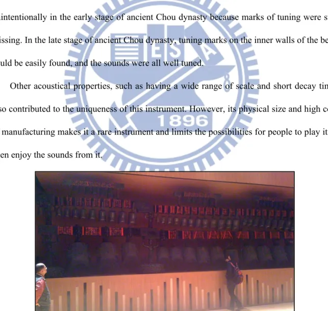
Figure 1.1. A replicated set of Marquis Yi of Zeng’s Chime-bells in Zhongshan hall, Taipei. . 3
Figure 1.2. Two strike points on the bell for emitting two pitches. ... 4
Figure 2.1. First six modes in Chinese two-tone bells [22]. ... 8
Figure 2.2 Components of the traveling wave after being plucked [16] ... 10
Figure 2.3 Initial conditions for the ideal plucked string [16]. ... 11
Figure 2.4 The plucked-string model [28] ... 13
Figure 2.5 Configuration of two-dimensional digital waveguide mesh [30] ... 15
Figure 2.6 Configuration of three dimensional tetrahedral mesh structure [31] ... 15
Figure 2.7. A banded digital waveguide model [33]. ... 16
Figure 2.8 The inharmonic digital waveguide model [35] ... 17
Figure 3.1 Configuration of a complete bell set and the naming rule of the bells. ... 23
Figure 3.2 (a) The “Knob bell” (b)(c) The “Yong bell” ... 24
Figure 3.3 Microphone setup for sample recording. ... 25
Figure 3.4 APE of the bells on the first rack ... 26
Figure 3.5 APE of bells on the second rack ... 27
Figure 3.6 APE of the bells on the third rack ... 27
Figure 3.7 Waveforms of 1_T_2 (a) Sui tone (b) Gu tone ... 29
Figure 3.8 Spectra of 1_T_2 (a) Sui tone (b) Gu tone ... 30
Figure 3.9 Waveforms of 1_M_10 (a) Sui tone (b) Gu tone ... 31
Figure 3.10 Spectra of 1_M_10 (a) Sui tone (b) Gu tone ... 32
viii
Figure 4.2. Force pulses of different initial velocities ... 34
Figure 4.3 (a) Original signal and (b) excitation signal of 1_T_1 Sui tone ... 36
Figure 4.4 Block diagram of the Chime-bell model 1 ... 37
Figure 4.5 Block diagram of the Chime-bell model 2 ... 38
Figure 5.1 Recorded Sui and Gu tones of 1_T_1 (a)(b), 1_M_1(e)(f); Synthetic Sui and Gu tones of 1_T_1 (c)(d), 1_M_1 (g)(h) ... 40
Figure 5.2 Spectra of recorded and synthetic tones of (a) 1_T_1 Sui tone (b) 1_T_1 Gu tone 41 (c) 1_M_1 Sui tone (d) 1_M_1 Gu tone ... 41
Figure 5.3 Recorded Sui and Gu tones of 1_M_11 (a)(b), 1_B_2(e)(f); Synthetic Sui and Gu tones of 1_M_11 (c)(d), 1_B_2 (g)(h) ... 43
Figure 5.4 Spectra of recorded and synthetic tones of (a) 1_M_11 Sui tone (b) 1_M_11 Gu tone (c) 1_B_2 Sui tone (d) 1_B_2 Gu tone ... 44
1
1. Introduction
1.1. Background
Since 1960, everything has been evolving so drastically that the world envisioned by Dr. Feynman in his famous speech [1] is now our reality. From vacuum tube to integrated circuits, things are breaking through the limitation of scale and blending into our lives in different forms and shapes. Musical instruments, as being important inventions in human culture, are also impacted by these major changes. For instance, synthesizers and electronic musical instruments are becoming more and more popular for their expansibility and playability in sounds; Digital forms of conventional musical instruments are being created as apps1 in many mobile devicesfor their convenience and mobility; Various innovate musical instrument are being crafted, allowing more creativity and possibility of sound to be implemented. All of these not only symbolize the great advance of modern technology, but also the power of digital signal processing (DSP).
As the development of digital signal processing continues to thrive, many sound synthesis algorithms have been proposed. With the help of the increased computational power, more accurate and complex synthesis models can now be achieved with high efficiency and low cost, and more virtual instruments can be thus constructed systematically[2][3][4]. A well-developed sound synthesis model for a conventional musical instrument will not only serve as a digital copy of it, but also a starting point for creating imaginary sounds based on
2
its original acoustical properties. That is to say, the gap between retrospective and futuristic sounds of a musical instrument could be bridged through the understanding of acoustics and development of sound synthesis models.
Therefore, it is meaningful to study the nature of traditional musical instruments and reinterpret them as computational models for better control over sounds. In the following sections, more lights will be shed on the Chinese instrument called the Chinese Chime-bells (or the Chinese two tone bells) and model-based sound synthesis.
1.1.1. Chinese Chime-Bells
The Chinese Chime-bell is one of the ancient percussion instrument from China, and it is also one of the most important inventions in Chinese history [5]. Generally, the Chinese Chime-bell is oval in shape, which is different from Western bells. The most famous set of the Chime-bells of all time is probably the one discovered in the tomb of Marquis Yi of Zeng in 1978 [6]. Those bells had soon been identified as cultural legacies that could date back to 433 B.C.
As shown in Fig. 1.1, the whole set is consisted of 65 bells of different pitches and sizes, and the primary material of the bells is bronze. There are three racks of bells, each rack has three levels, and the bells are placed on each level in order. Having a total weight of over 4400 kg, the complete bell set is a collection of bells with significant disparity. For example, the smallest bell is about 20 cm in height and 2.4 kg in weight, and the largest bell is about 150 cm in height and 203 kg in weight. Such great differences also reflected on their sounds. The complete set of Chime-bells has a scale of over 5.5 octaves, which is comparable to
3
modern instruments. Most of the bells are engraved with delicate symbols and have inscription on the surface, demonstrating the polished crafting skills of the ancient civilization. In short, the Chinese Chime-bell is an incredible creation even from the perspective of modern technology.
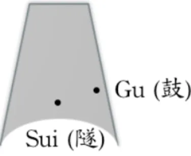
The most important acoustical feature of the Chime-bells is its capability of producing two pitches from one single bell. As shown in Fig. 1.2, when the bell is struck at the Sui point and the Gu point, two different tones will be emitted. Normally, the interval between these two tones is major or minor third. According to previous studies [7], this feature was formed unintentionally in the early stage of ancient Chou dynasty because marks of tuning were still missing. In the late stage of ancient Chou dynasty, tuning marks on the inner walls of the bells could be easily found, and the sounds were all well tuned.
Other acoustical properties, such as having a wide range of scale and short decay time, also contributed to the uniqueness of this instrument. However, its physical size and high cost of manufacturing makes it a rare instrument and limits the possibilities for people to play it or even enjoy the sounds from it.
4
Figure 1.2. Two strike points on the bell for emitting two pitches.
1.1.2. Model-based Sound Synthesis
Digital sound synthesis has been under its way for more than fifty years [8], and a myriad of synthesis techniques have been presented. Early synthetic techniques such as additive synthesis [9], wavetable synthesis, AM and FM synthesis [10] are simple and efficient methods for synthesizing sounds. However, to mimic the sounds of certain musical instruments and control the sounds according to their physical descriptions, more complex models based on acoustics of the musical instruments are needed. Such models, which can be referred as physical models, are the core of virtual instruments [3][11][12].
There are two general goals of physical modeling synthesis, one is to fully understand the sound-producing mechanism of traditional instruments in order to generate realistic sounds, and the other is to create imaginary sounds based on the acoustics of the instrument. Many approaches, such as solving wave equation of vibrating objects [13], mass-spring paradigm [14], modal synthesis [15], or digital waveguides (DWG) synthesis [3], [16], have been proposed to create intricate models of musical instrument. However, most of the approaches share one common drawback of being computational demanding. The degree of authenticity of a sound is normally highly proportional to the computation load, and this could
5
potentially increase the difficulty of real-time implementation. Fortunately, this issue has lessened due to the rapid growth of computational power lately.
Recently, more and more commercial electronic musical instruments such as Yamaha VL1 and Korg Wavedrum are integrating physical modeling synthesis into their systems for qualitative sounds and high interactivity, showing its potential in realizing virtual instruments.
1.2. Motivation, Goal and Organization
As mentioned before, the Chinese Chime-bell has many interesting acoustical properties like two-tone per bell, short decay time, and a wide range of pitch scale. These features are attractive to composers and audiences. However, this ancient musical instrument is currently underused for being too large in size and too expensive to build. This makes virtual instrument a very appealing solution to the problem.
A synthesis model has many advantages over recording samples: (1) Synthesized sounds are free from environmental noises or interruptions. (2) The system requires less memory. (3) The playability over sound is higher. Besides, well-developed models will be able to generate realistic sounds and be built as electronic instruments, bringing new life to this traditional musical instrument. Most studies about physical modeling of musical instruments mainly focused on Western musical instruments such as guitar [17], piano [18], and woodwind instruments [19], only a relatively few attentions were put on Eastern musical instruments such as Guqin [20] and Pipa [21]. Hence, it will be beneficial to investigate such ancient Chinese instrument and increase the diversity of this field.
6
Chime-bells and construct an efficient sound synthesis model accordingly. The organization of the thesis is described as follows: In Chapter 2, previous studies on the acoustics of the Chinese Chime-bells and waveguide-based sound synthesis models will be reviewed. In addition, an efficient synthesis model for bell sounds through the use of inharmonic digital waveguides will be discussed. Analysis results of the samples from a replicated set of the Chinese Chime-bells will be presented in Chapter 3. In Chapter 4, two synthetic models of the Chime-bells based on inharmonic digital waveguides will be introduced, and the synthetic results from the models will be later presented in Chapter 5. Lastly, the conclusions and future works will be addressed in Chapter 6.
7
2. Previous Studies
2.1. Acoustical Features of Chime Bells
Ever since its discovery in 1978, the Chinese Chime-bells have received a lot of attentions from archeologists and scientists worldwide. In addition to its cultural value, the Chinese Chime-bells also shine for being acoustically unique. Unlike Western bells [22], the Chime-bells are capable of producing two separated tones on one bell, and the sound of the bells attenuates more quickly. Many studies and experiments have been conducted to further understand the principles behind these features.
2.1.1. Dual Tones
To account for this phenomenon, many works have been done, including both experiments and simulations. Vibrational modes of a modern copy of Chinese two-tone bell was first studied by Rossing et al. by means of holographic interferometry as well as the sound field scan [23]. The modal shapes were revealed by the reconstructed images of holographic interferometry and confirmed by scanning the sound field near the bell. The results showed that the vibrational modes tend to exist in pair, that is to say, with the same number of nodal meridians (denoted by m) and nodal circles (denoted by n), two different modes will be found. As shown in Fig. 2.1, the pair of modes can be labeled as (m,n)a and
(m,n)b, and different striking points will excite different modes. If one mode (m,n)a has nodes
8
suppress the later mode. Otherwise, both modes will be equally strong in the spectrum of both Sui and Gu tones. In addition, it was found that the vibrational modes of Chinese two-tone bells are more similar to the hand-bells for not having heavy sound-bow and pronounced flair at the bell mouth. To further confirm the mechanism, the finite element method had been applied to simulate the response of the bell body [24] [25], and both results suggested that asymmetry of the bell body contributed the most to its dual tone nature. Also, the two-tone effect of the bell was simulated by a double-circular arch [26], and the relationship between the frequencies of each tone could be thus calculated numerically. Results showed that as the half central angle of each arch decreases, the frequency ratio between the first two modes would increase.
Figure 2.1. First six modes in Chinese two-tone bells [23].
2.1.2. Short Decay Time
Another feature of the Chime-bells is to have sounds that fade away much faster than other kinds of bells. The power radiation of a double-circular arch was calculated to simulate this phenomenon [26]. By changing the geometry factors of the simplified model, attenuation coefficient could be estimated. The results indicated that the more oblate the bell is, the more quickly the sound attenuates.
9
This feature was also demonstrated by estimating the pressure changes inside the bell body [27]. Results showed that the damping coefficient of the oblate-shaped bell was higher than round-shaped bell due to the curvature, rigidity and amplitude on the central part, causing the energy to dissipate faster and leading to shorter decay time.
2.1.3. Other properties
The effect of many nipple-like ornaments (also known as Mei) on the bell body was also studied [27], and a modern copy of the Chime-bells was used to conduct the experiment. As the ornaments being grinded out little by little, the spectrums of the bell sounds were recorded. According to the results, these ornaments actually served as low-pass filters that will cut off high frequencies components of the bell sound. The longer they are, the better filtering effects they will achieve.
In addition, the experiments on the variations of the bell sounds caused by temperature changes were conducted [28]. By heating a miniaturized model of the Chime-bell, the changes of the sounds could be recorded and analyzed. It was found that the frequency and decay time of the bell sound increased as the temperate rising up.
2.2. Sound Synthesis Based on Digital Waveguides
2.2.1. Basic Concept of Digital Waveguides
10
to model various musical instruments successfully [17–19], [21]. The simple orientation and high compatibility with digital filters makes it an appealing solution for constructing virtual instruments. The basic concept of digital waveguides is based on the traveling wave solution of the lossless, one-dimensional wave equation derived by d’Alembert in 1747. As shown in Fig. 2.2, when an ideal string is first plucked, two traveling wave components are at the same position and the triangle-shaped wave will form up. These components will start to departure from each other right after the release of the pluck, and the displacement at the point of the ideal string can be considered as the net effect of two traveling wave components. If the speed is denoted by c, the right going component is denoted by yr(x-ct) and the left going
component is denoted by yl(x-ct), the relationship can be described as the following equation :
𝑦 𝑥, 𝑡 = 𝑦! 𝑥 − 𝑐𝑡 + 𝑦! 𝑥 + 𝑐𝑡 (2.1)
Figure 2.2 Components of the traveling wave after being plucked [16]
Based on this expression, the digital waveguides can be seen as the sampled version of this traveling wave solution. For a given sampling frequency fs = 1/T, the sampling interval T
11
could be obtained. By assuming the traveling speed of the wave to be c, the spatial sampling interval X could be calculated as X=cT. As a result, any string of length L could be thus expressed as N samples, where N= 2L/X. As shown in Fig. 2.3, an ideal string of length L is modeled by digital waveguides. The waveguides consist of two delay loops, and each loop is for the traveling wave component of specific direction. When the digital waveguides are initialized with a pluck, both components will start to travel, and the displacement of any point along the string could be calculated by summing up the components. If the string is fixed ideally, the traveling waves will rebound inversely at the rigid ends. Therefore, The boundary conditions of both loops could be set as -1 for lossless traveling. On the contrary, if the damping effect of both ends is taken into account, the boundary condition could be modified accordingly. The frequency of the model is determined by the string length since f =
fs / N and N= 2L / X.
12
As being the central component of many virtual instruments, digital waveguides have the advantage of producing harmonic-rich sounds easily while retaining the essential physical meanings of the traveling wave solution. It is hence very suitable for models involving one-dimensional vibrations.
2.2.2. Karplus-Strong String Model
Another approach similar to the digital waveguide modeling was the synthesis method known as Karplus-Strong algorithm [29]. The original algorithm was proposed as a wavetable-based synthesis method for producing plucked-string and drum like sounds through the basic structure of a feedback delay loop. The plucked-string model is shown in Fig. 2.4, and the wavetable is initialized with random numbers at the beginning. This is to simulate the energy distribution of the plucking impulse that is very similar to white noise. The wavetable will go through an averaging feedback process that serves as a low-pass filter, creating a frequency-dependent damping effect to the output sound. This makes the output sound more realistic since high frequency components tend to decay faster than low frequency components. In fact, this model can be considered as a simplified waveguide model connected with a loop filter. Combining the delay loops of the digital waveguides and canceling out the -1 at the rigid ends will transform the digital waveguides to the structure of Karplus-Strong string model.
13
Figure 2.4 The plucked-string model [29]
The sound produced from the Karplus-Strong model is pretty convincing, yet there are still some disadvantages to be addressed. First of all, the random numbers in the wavetable determines the input, and the output signal is thus generated with fixed energy distribution of all frequencies. In the real case, a stronger pluck is very different from a soft pluck in their frequency distribution. Secondly, the sample number of the delay line is always an integer, which means that some frequencies are unable to be generated when the sampling frequency is fixed. Moreover, the stiffness of the string will tend to make the sound a little inharmonic, and this feature is ignored in the primary model. To solve these problems, an extended model was later proposed [30] . Different digital filters are included in the modified model for the authentic sounds. For instance, the fractional delay filter is accounted for the tuning issue, the stiffness all-pass filter is for the inharmonicity, and the variable bandwidth low-pass filter is for the dynamic level adjustment.
However, the models described above are mainly about the vibrations of one-dimensional objects such as string. To simulate the sound-producing mechanism of higher dimensional objects, other models are needed.
14
2.2.3. Two Dimensional Digital Waveguide Mesh
The two dimensional digital waveguide mesh is an extended version of the original waveguide model for higher dimensional vibrations [31]. The basic structure is shown in Fig. 2.5. The membrane could be expressed as N strings crossing together, creating many intersections. These intersections, assumed to be lossless junctions that will not cause any energy loss, have to satisfy two conditions: (1) The velocities of all string at the junctions must be equal since all of them are moving simultaneously. Such that could be expressed as:
𝑣! = 𝑣! = ⋯ = 𝑣! (2.2)
(2) The forces at every junction must balance each other and sum to zero:
𝑓!+ 𝑓!+ ⋯ + 𝑓! = 0 (2.3)
Besides, the force and velocity of the traveling wave could be related to the impedance as: 𝑓! = 𝑅𝑣!
𝑓! = 𝑅𝑣! (2.4)
The right going and left going forces are denoted by 𝑓! and 𝑓!, and the 𝑅 = 𝑇𝜀 !.!
where T is the constant tension on strings and the 𝜀 is the mass per unit length. Many lossless scattering junctions interconnect the delay units, creating a network of transportation passages. When an initial force was loaded on the network, the wave will propagate through the delay units and spread out like ripples. The impedance of the scattering junctions could be adjusted to damp the force as it proceeds.
In addition to two-dimensional surfaces, higher dimensional objects could potentially be modeled through the construction of such waveguide mesh as well. For instance, a cubic scattering junction could be build by adding two more ports on the original one, forming a
15
basic element for constructing three-dimensional structures. Moreover, the tetrahedral mesh [32] was further presented to fill the same volume with less scattering junctions as shown in Fig. 2.6. However, for objects with complex configurations, these models will become very complex and the computational loads will hence increase.
Figure 2.5 Configuration of two-dimensional digital waveguide mesh [31]
Figure 2.6 Configuration of three dimensional tetrahedral mesh structure [32]
A B C D E 1 2 3 4 5 6 7 8 9 10 11 12 Scattering Junction A Scattering Junction B VAB– VAB+ VBA– VBA+ z-1 z-1
16
2.2.4. Banded Digital Waveguides
Another approach to model objects with complex spectrum is through the use of digital waveguides banded in frequencies [33][34]. As stated before, the digital waveguide model is suitable for one-dimensional vibration like string, and the sound is expected to be much harmonic. However, for stiff objects like rigid bar or cymbals, the inharmonicity could be difficult to model through the combination of the original waveguide model and digital filters. Therefore, to address this issue, the spectrum of the vibrating system could be divided into different frequency bands, and each band could be modeled by a different digital waveguide. The number of bands to be divided can be determined according to the number of modes to simulate. This method can also be considered as a hybrid system of the spectral model and digital waveguide model.
17
2.2.5. Inharmonic Digital Waveguides
For rigid objects such as bells, the inharmonicity caused by the stiffness cannot be ignored. To simulate the feature, an efficient model through the use of inharmonic digital waveguides has been proposed [35–37]. The original digital waveguides are suitable for synthesizing harmonic sounds with exponential decays. By adding a second order all-pass filter into the feedback delay loop, the waveguide model will be able to generate sounds with stronger inharmonic partials. The second-order all-pass filter is chosen on the account of the balance between authenticity and efficiency. For psychoacoustic reasons, three matched frequencies will make a pretty convincing sound of bell. Therefore, a second-order all-pass filter is enough for this number of partials. The pole of the all-pass filter can be placed to attract nearby partials, causing them to shift away from their original positions and leading to inharmonicity. This approach provides a simple and efficient solution to the construction of bell model.
Figure 2.8 The inharmonic digital waveguide model [36]
2.3. Implementation of Inharmonic Digital Waveguides
18
waveguide model is not enough to simulate its vibrational behaviors. A digital waveguide mesh with multiple delay units and scattering junctions could be a better solution, however, it is very hard to build such model while maintaining the efficiency of computation. In order to synthesize the sound of the Chinese Chime-bells more efficiently, an inharmonic digital waveguide model could be adopted. The components of the inharmonic digital waveguide include a basic delay loop of the digital waveguide, a fractional delay filter, a loss filter and an inharmonic all-pass filter. The implementation of these filters are described as follows:
2.3.1. Fractional Delay Filter
As described in section 2.2.1, any given string could be divided by the spatial sampling interval X into N samples. This N will equal to the length of the delay line. Considering the case when the sampling frequency is constant, for any desired frequency f, N might not always be an integer since 𝑓 = 𝑓!/𝑁. When N is a non-integer multiple of X, a fractional
delay is required. A fractional delay filter can also be considered as an interpolator for the values between n and n+1. There are many ways of implementing fractional delay filters [38][39], including forms in both IIR (Infinite impulse response) and FIR (Finite impulse response). Fractional filters in FIR forms have the advantages of being non-recursive and linear phase. However, the amplitude at higher frequencies will suffer from degradation. When the sampling rate is not high enough, this undesirable decrease in amplitude will be audible. On the contrary, fractional filters in IIR forms, especially all-pass filters, will have uniform distribution over different frequencies. For fractional delays between 0 to 1 samples, a first order all-pass filter is suitable for the implementation. The transfer function of the first
19
order all-pass filter is shown in (2.5)
𝐻 𝑧 = 𝜂 + 𝑧!! 1 + 𝜂𝑧!! 𝜂 ≈1 − ∆ 1 + ∆ (2.5)
The ∆ equals to the fractional part of the delay line. This approximation works best when ∆ is wholly above zero [3].
2.3.2. Loss Filter
In this case, a FIR filter is a suitable choice for implementing loss filter since the group delay is the same at all frequencies. A low order FIR filter will render pretty good frequency-dependent damping effects to the synthetic sounds. A simple way to design a second order FIR loss filter has been described in [3]. The sound can be controlled by two parameter of brightness B and sustain S. The parameters of the filter can be defined as:
𝑔! = 𝑒(!!.!"! !)
𝑔 0 = 𝑔!(1 + 𝐵)/2
𝑔 1 = 𝑔!(1 − 𝐵)/4 (2.6)
The P is the period of total loop in seconds, the B is the brightness ranging from 0 to 1, and the S is the desired decay time in seconds. The time constant for a sound to decay by 60
20
dB is approximately equal to 6.91. This parametrical control of filter provides an efficient way to design a loop filter for the feedback delay loop.
2.3.3. Inharmonic All-pass Filter
The core component inside the delay loop of an inharmonic digital waveguides is the all-pass filter. The effects of an all-pass filter to in a digital waveguide delay loop has been studied in [35]. According to [36], a second order all-pass filter is enough to match the first three partials of the target sound. A second order all-pass filter can be designed by adjusting the r and the 𝜃 of a pole [40]. The transfer function can be expressed as:
𝐻!" 𝑧 = (𝑧!!− 𝑟𝑒!")(𝑧!!− 𝑟𝑒!!")
(1 − 𝑟𝑒!"𝑧!!)(1 − 𝑟𝑒!!"𝑧!!) (2.7)
Since the magnitude response of an all-pass filter is unity for all frequencies, it will
inevitably cause phase distortion. By setting the pole of the all-pass filter to the right position, nearby frequencies will be affected by this non-linear phase delay. The phase delay of the second order all-pass filter could be expressed in the following equation:
𝜙!" 𝑤 = −2𝑤 − 2 𝑎𝑐𝑟𝑡𝑎𝑛 !!! !"# (!!!)! !"#(!!!) − 2 𝑎𝑐𝑟𝑡𝑎𝑛 !!! !"# (!!!)! !"#(!!!) (2.8)
When loop filters are not taken into account, a digital waveguide with a delay line of length L has a phase response of 𝜙!"# 𝑤 = −𝐿𝑤. As a result, the overall phase response
21
of the inharmonic digital waveguide could be expressed as:
𝜙!"#$ 𝑤 = 𝜙!"# 𝑤 + 𝜙!" 𝑤 (2.9)
The resonant frequencies wi of the inharmonic digital waveguide will appear at
𝜙!"#$ 𝑤! = −2𝜋𝑖 where 𝑖 = 0, 1, 2, … (𝐿 − 1) . Therefore, the shifted peaks of the
inharmonic digital waveguide could be estimated.
There are certain limitations of the inharmonic all-pass filter [36]. First, the main effect of the all-pass filter is to attract the partials close to the frequency of the pole. The best situation for this effect to take place is when the second partial and third partial are both less than 2 and 3 times of the first partial, for example, 𝑓2 = 1.85𝑓1 and 𝑓3 = 2.65𝑓1. Next, in certain cases when the partial squeezing is too strong, the resulting filter could be unstable. For instance, if the second partial is the only partial to be shifted, the frequency difference between the second partial and the third partial could become too large, leading to a undesirable filter that might create extra unwanted peaks.
The filter design can be achieved through an iterative process. To begin with, the desired ratio of the second and the third partial to the first partial can be set, for example, 𝑓2 = 1.85𝑓1 and 𝑓3 = 2.65𝑓1. By changing the r and the 𝜃 of a pole, the new resonant frequencies of the loop with an inharmonic all-pass filter could be calculated, and the ratios of the target partials to the first partial could also be obtained. A recursive function could be employed to design new filters until the difference between the resulting ratios and the desired ratios is within the predetermined tolerance.
22
3. Acoustic Signal Analysis
3.1. Chime-Bells sampling
To study the acoustical properties of the Chime-bells, qualitative samples from the bells are needed. In this thesis, the sounds from a replicated set of Marquis Yi’s Chime-bells have been sampled and analyzed as the reference for the synthetic sounds.
When the Chime-bells were first discovered in the tomb of Marquis Yi of Zeng in 1978, three copies were made directly from the mold of the original set. In 1997, the ministry of culture of Taiwanese government purchased one of these finest replicas from Hubei museum. This set, governed by the National Center for Traditional Arts1, is currently stored in Taipei Zhongshan Hall2 and maintained by the Taipei Chinese Orchestra3. It has been played in many concerts by the Taipei Chinese Orchestra and still in very good condition.
The sample recording was taken place in Taipei Zhongshan Hall, a concert hall that could contain approximately two thousand audiences at a time. Since the space is designed specifically for musical performances, the environmental noises have been reduced to the minimum level. However, the mechanical noises from the cooling system of the transformer behind the main stage are inevitably recorded as background noises. The room temperature during the recording process was about 25 degree Celsius.
The configuration and the naming rule of the Chime-bells are shown in Fig. 3.1. There
1 For more information, please visit: http://www.ncfta.gov.tw/ncfta_ce/main/index.aspx 2 For more information, please visit: http://www.csh.taipei.gov.tw/
23
are three racks of bells, each rack has three levels, and the bells are placed on each level in order. A total of 65 bells are included in this set, and 64 of them are two-tone bells. One exception is the “Bo bell1”, which is only capable of producing one tone. As shown in Fig. 3.2, there are mainly two types of bells in the set. One is the bells located on the top level, which is known as the “Knob bell2”. The other is the bells located on the middle and bottom levels, which are known as the “Yong bell3”. As shown in Fig. 3.1, each bell is named according to its position.
For every bell, both the Sui and Gu tones were sampled. A well-trained musician performed every note, and the force of each strike was asked to be as equal as possible.
Figure 3.1 Configuration of a complete bell set and the naming rule of the bells.
1 鎛鐘 2 鈕鐘 3 甬鐘
24
Figure 3.2 (a) The “Knob bell” (b)(c) The “Yong bell”
The equipment list is shown in Table 3.1. Two condenser microphones were used in the recording process, one is for the direct sound from the instrument, and the other is for the ambient sound of the room. The setup of the microphones is illustrated in Fig. 3.3. The distance R is about 1 meter, and the two microphones are separated by 3R to avoid the problem of phase cancellation. These sound tracks were later mixed and stored in the computer. The samples were all recorded and save in the format of 88.2 kHz sampling rate and 24-bit resolution.
Table 3.1 Specs of the recording equipment.
Item Model Specs
Condenser Microphone AKG Perception-170 12mV/Pa (-38 dBV)
Condenser Microphone Rode NT-5 12mV/Pa (-38 dBV)
25
Figure 3.3 Microphone setup for sample recording.
3.2. Sound Analysis
3.2.1. Pitch Discrimination
As mentioned before, the recorded samples used in this thesis were taken from a replicated set of the Marquis Yi’s Chime-bells. Although the set was well reproduced, slight deviations might still exist. According to [6], the fundamental frequencies of all bells were measured by three different groups after the discovery of the tomb of Marquis Yi of Zeng. These data could be used to investigate the differences between the original set and the replicated set. The fundamental frequencies of the recorded samples in this thesis have been measured through Fast Fourier Transform (FFT) with the hamming window and a window length of 8096 samples. The pitch discrimination of fundamental frequencies between these two set can be thus calculated.
Pitch discrimination means the ability to hear the small difference in pitch. According to the study [41], the average threshold of adults is about 3Hz at the pitch of 435Hz, which is about 1/17 of a whole tone. However, for people who are very sensitive to sounds, the threshold could be less than 1/100 of a tone. In musicology, the interval of a semi-tone can be divided into 100 cents. Therefore, the threshold described above can be converted to 12 cents
26
and 2 cents respectively. According to equal temperament, the frequency ratio between two adjacent notes is roughly equal to !" 2≈ 1.0595, and the frequency ratio of a whole tone can be calculated as 1.0595! ≈ 1.1225. Then, the threshold of pitch discrimination could be
converted to a percentage error of 0.72%.
To find out if there is any significant difference in pitch for every bell, the absolute percentage error between the original set and the replica could be calculated in (3.1), where Va
is the actual value and Vm is the measured value:
𝐴𝑏𝑠𝑜𝑙𝑢𝑡𝑒 𝑃𝑒𝑟𝑐𝑒𝑛𝑡𝑎𝑔𝑒 𝐸𝑟𝑟𝑜𝑟 𝐴𝑃𝐸 = 100% × !!!!!
!! (3.1)
For each bell, the mean value of the three measurements from [6] is used as the actual value. The APE of all bells has been estimated. The results are shown in Fig. 3.4, 3.5 and 3.6.
27
Figure 3.5 APE of bells on the second rack
28
Table 3.2 Counts of tones under the threshold.
Racks Under Thresh. Exceed Thresh. Total Percentage
1st 31 9 40 77.5%
2nd 33 13 46 71.7%
3rd 31 11 42 73.8%
Total 95 33 128 74.2%
The statistic results of the counts on bells under the threshold have been shown in Table 3.2. Since there are 64 two-tone bells, a total number of 128 tones have been evaluated. As a result, about 74.2% of tones are under the threshold of pitch discrimination. That is to say, most of the fundamental frequencies from the replicated set are perceptually the same with the original set to most people. Besides, the first rack has the highest percentage of tones under the threshold, which means the quality of the first rack could be higher. As a result, the recorded samples are acceptable as being the reference for synthetic sounds.
3.2.2. Spectral Analysis
To gather more information from the recorded samples, both the time and frequency domain features of the signals have been examined. Among the 65 bells on the racks, 13 bells have fundamental frequencies higher than 1000Hz, and 52 bells have fundamental lower than 1000Hz. These two groups of bells have different acoustical features. For bells with higher fundamental frequency, such as the first three bells on the top and middle levels of the rack,
29
the decay times are short and the sounds are more clear and bright. Take 1_T_2 for example, the waveforms of both Sui and Gu tones are shown in Fig. 3.7. Both sounds decay very fast and smooth after being struck. The spectra of 1_T_2 are shown in Fig. 3.8. The fundamental frequency of the Sui tone and the Gu tone are 1391 Hz and 1780 Hz respectively. As discussed previously, the geometrical design of the Chime-bells will cause the vibrational modes to exist in pair, allowing two distinguished tones to be produced on the same bell. Although the mode (m,n)a and (m,n)b are supposed to suppress each other due to the positions
of their nodes and antinodes, they still tend to coexist in both the Sui tone and the Gu tone. Results can be found in Fig. 3.8 that the frequency components in both sounds are very similar except for their magnitudes. This result suggests that the sounds of the Chime-bells could be the weighted combination of two different groups of modes.
Figure 3.7 Waveforms of 1_T_2 (a) Sui tone (b) Gu tone (a)
30
Figure 3.8 Spectra of 1_T_2 (a) Sui tone (b) Gu tone
In addition, the pairs in the spectra could be identified through observation of spectra of the sounds. For instance, in Fig. 3.8, the peaks at 1391 Hz and 1780 Hz can be considered as the first pair, the peaks at 2521 Hz and 2902 Hz as the second pair, and the peaks at 3828 Hz and 4049 Hz as the third pair. The ratios between these pair are slight less than 2 and 3 times of the fundamental frequencies of Sui and Gu tones. Similar features could be found on the bells with higher fundamental frequencies such as 1_T_1, 1_M_1…etc. The spectral contents of these bells are relatively simple compared to bells with lower fundamental frequencies.
For bells with lower fundamental frequencies, such as bells on the middle and bottom levels of the rack, the decay times are slightly longer and the sounds are drier and darker for more partials located in lower frequencies. Besides, the frequencies partials above 5000 Hz are strongly suppressed in these bells. This could be the low-pass effects caused by the installation of Mei [27]. Take 1_M_10 for example, the waveforms of both Sui and Gu tones
(a)
31
are shown in Fig. 3.9. Both sounds still attenuate fast except for some low frequency partial which tend to last a bit longer. The spectra of 1_M_10 are shown in Fig. 3.10. The fundamental frequency of the Sui tone and the Gu tone are 323 Hz and 407 Hz respectively. The weighted combination can still be observed in Fig. 3.10; for instance, the peak of 323 Hz appears to be weaker in the Gu tone. However, the distribution of pairs in the spectra is different from previous case. The second and third pairs are more distant, and the ratios between these pairs and the first pair are higher than 2 or 3. Similar features could be found on the bells with lower frequencies such as 1_M_11, 1_B_1…etc, and their spectral contents are more complex compared to bells with higher fundamental frequencies. Additionally, the decay time of bells on the bottom level can be significantly longer, and the beating effect will be stronger too.
Figure 3.9 Waveforms of 1_M_10 (a) Sui tone (b) Gu tone (a)
32
Figure 3.10 Spectra of 1_M_10 (a) Sui tone (b) Gu tone (a)
33
4. Sound Synthesis of the Chime-Bells
4.1. Description of the Synthesis Model
In Fig. 4.1, the block diagram of the sound synthesis model of the Chime-bells has been shown. The essential parts of the model include an input dynamic control and a bell model. The dynamic control consists of the excitation table and a low-pass filter is to simulate the non-linear behavior of the strike. It has been achieve by changing the low-pass filter according to the collision velocity Vc. The bell model includes mainly two rails of inharmonic
digital waveguides. The weighting combination of the waveguides and the parameters of the filters could be adjusted by the users, creating different bell sounds.
Figure 4.1 Block diagram of the Chime-bell synthesizer
4.2. Dynamic filter and Extraction of Excitation Signals
For most musical instruments, playing with different initial velocity will cause not only the changes in amplitudes but also in timbres. To simulate this effect, a dynamic filter is
34
needed. In real performance, different tools have been used to play the Chime-bells according to their position on the racks. For bells on the top and middle levels of the rack, a small mallet is used to strike the bell. For bells on the bottom level of the rack, a wooden pillar wrapped by rubbers is used. This mechanism is pretty similar to the interaction between hammer and string in piano [18] despite of the differences in sizes and physical shapes. In the hammer string case, the force pulse from the hammer has non-linear behaviors due to the felt on the hammer. Therefore, as the strike getting harder, the force pulse will be narrower in time domain and wider in frequency domain. This idea is illustrated in Fig. 4.2:
Figure 4.2. Force pulses of different initial velocities
In this thesis, the interaction between the mallet and the bell is reduced to a single impulse. That said, no further contact after the first collision. Besides, the bell is assumed to be static before the strike. As a result, the net velocity is equal to the input collision velocity
Vc. A one pole low-pass filter is set to simulate the spectral changes of the input excitation.
35
dynamic filter is shown in equation (4.1):
𝐻! 𝑧 = 𝑏!
1 − 𝑎!𝑧!! (4.1)
In (4.1), 𝑎! = 𝑒!!"#, T is the sampling frequency, and L is the desired bandwidth in Hz.
Here the range of L from 0 to fs/2 is mapped to the range of the input velocity from 0 to 127.
The 𝑏! is equal to 1 − 𝑎! so the peak gain will equal to unity as z approaches to 1.
For every different collision velocity, a low-pass filter with different bandwidth will be set to modify the excitation signals. For instance, when the collision velocity is higher, the bandwidth of the filter will become wider.
The excitation table is a collection of different excitation signals extracted through inverse filtering [17]. This process is achieved by putting the recorded samples through the inverse filter 𝐴 𝑧 = 1/𝐻!(𝑧) where 𝐻!(𝑧) symbolizes the transfer function of the inharmonic digital waveguides in the Chime-bell model. This inverse filter will suppress the least-damped partials in the original samples, leaving a short bursting signal of most-damped partials. As shown in Fig. 4.3, the residual excitation signal dies out quickly compared to the original signal. The excitation signal contains information of the strike sound and the prediction error of the bell model. Normally, excitation signals with a length of 50 to 100 ms are enough to be fed into the bell model.
36
Figure 4.3 (a) Original signal and (b) excitation signal of 1_T_1 Sui tone
4.3. Bell Models
As described in section 3.2.2, the distribution of the frequency components of the bells with different fundamental frequencies is different. To cover up the entire range of the bells with different fundamental frequencies, two bell models have been developed.
The block diagram of the first Chime-bell model is shown in Fig. 4.4. As discussed previously, the sound of the Chime-bells with higher fundamental frequencies (Typically higher than 1000Hz) can be considered as the weighted combination of two groups of modes. Therefore, two inharmonic digital waveguides are used to produce the partials of (m,n)a and
(m,n)b respectively. Partials are determined through the observation of spectra of the recorded
sounds. The inharmonic digital waveguide is basically a filtered feedback comb filter. The users could determine the weighting coefficients of both rails arbitrarily. To imitate the real sounds, the coefficients can be set based on the dB ratio of their fundamental frequencies from spectral analysis. As mentioned in section 2.3, the loop filters of an inharmonic digital waveguide include a fractional delay filter 𝐻!(𝑧), a loss filter 𝐻!(𝑧) and an inharmonic
(a)
37
all-pass filter 𝐻!"(𝑧). The transfer function of a single inharmonic digital waveguide can be
expressed as equation (4.2) where L is the length of the delay loop:
𝐻! 𝑧 = 1
1 − 𝐻!(𝑧)𝐻!(𝑧)𝐻!"(𝑧)𝑧!! (4.2)
Figure 4.4 Block diagram of the Chime-bell model 1
For bells with lower fundamental frequencies (typically lower than 1000 Hz), the model above should be adjusted according to the previous discussion in section 3.2.2. Since the fundamental frequencies are too separated from the other partials, a similar concept could be borrowed from [33] that frequencies are banded to account for this high inharmonicity. As shown in Fig. 4.5, two filtered digital waveguides are added to simulate the lowest two modes of the bell. A band-pass filter is connected to the digital waveguide to exclude the unnecessary partials from excitations. The original inharmonic digital waveguides with low order band-pass filters are to generate the rest of the partials of the other modes. This hybrid method will provide flexibility for this model to match partials of the real sounds while retaining the interpretation of the waveguides. Additional, an optional resonator is placed when the beating effect is strong.
38
39
5. Results and Discussions
5.1. Synthetic Results
The synthetic results from the models described in the previous section have been presented. All of the synthesized signals are calculated in the programming environment of Matlab.
5.1.1. Results from model 1
The first model described in section 4.3 can be employed to simulate the sounds from the Chime-bells with higher fundamental frequencies. These bells typically have fundamental frequencies higher than 1000 Hz and are smaller in size. 1_T_1 and 1_M_1 are the bells of this type. For 1_T_1, the fundamental frequencies of the Sui and Gu tones are 1986 Hz and 2332 Hz. For 1_M_1, the fundamental frequencies of the Sui and Gu tones are 1787 Hz and 2143 Hz. The parameters for loop filters can be determined by analyzing the recorded samples. For example, the inharmonic all-pass filter can be adjusted to match the essential partials identified, and the loss filter can be set based on the T60 of the real sounds. The
waveforms of the recorded and synthetic tones of 1_T_1 and 1_M_1 are shown in Fig. 5.1. Both the Sui and Gu tones have been simulated. Result can be found that the general shapes of the recorded and synthetic tones are similar. The spectra of these tones are shown in Fig. 5.2. It can be seen that there are fairly good matches on the lower frequency partials. However, mismatches can be found on the higher frequency partials.
40
Figure 5.1 Recorded Sui and Gu tones of 1_T_1 (a)(b), 1_M_1(e)(f); Synthetic Sui and Gu tones of 1_T_1 (c)(d), 1_M_1 (g)(h)
(a) (b)
(c) (d)
(e) (f)
41
Figure 5.2 Spectra of recorded and synthetic tones of (a) 1_T_1 Sui tone (b) 1_T_1 Gu tone (c) 1_M_1 Sui tone (d) 1_M_1 Gu tone
(a)
(b)
(c)
42
5.1.2. Results from model 2
The second model described in section 4.3 can be employed to simulate the sounds from the Chime-bells with lower fundamental frequencies. These bells typically have fundamental frequencies lower than 1000 Hz and are larger in size. 1_T_5, 1_M_11, and 1_B_2 are the bells of this type. For 1_T_5, the fundamental frequencies of the Sui and Gu tones are 653 Hz and 807 Hz. For 1_M_11, the fundamental frequencies of the Sui and Gu tones are 283 Hz and 344 Hz. For 1_B_2, the fundamental frequencies of the Sui and Gu tones are 72 Hz and 85 Hz. The process for determining the parameters of loop filters is basically the same with the first model. However, with the appearance of two additional digital waveguides, more pairs of partials need to be identified. The T60 of these bells are longer compared to the bells
with higher fundamental frequencies. For bells at the bottom level, the sound could last for 10 seconds or even longer. The waveforms of the recorded and synthetic tones of 1_T_5, 1_M_11, and 1_B_2 are shown in Fig. 5.3. Both the Sui and Gu tones have been simulated. Similar result can be found that the general shapes of the recorded and synthetic tones are still close. The spectra of these tones are shown in Fig. 5.4. It can be seen that there are fairly good matches on the lower frequency partials. However, mismatches still exist in the higher frequency partials. Note that for bells at the bottom level, the high frequency components above 5000 Hz are obviously absent. This might be the effect of Mei on the bell body discussed in previous studies [27]. This effect is successfully simulated with the additional band-pass filter connected to the original inharmonic digital waveguides.
43
Figure 5.3 Recorded Sui and Gu tones of 1_T_5 (a)(b), 1_M_11(e)(f), 1_B_2(i)(j); Synthetic Sui and Gu tones of 1_T_5 (c)(d), 1_M_11 (g)(h), 1_B_2 (k)(l)
(a) (b) (c) (d) (i) (j) (k) (l) (e) (f) (g) (h)
44
Figure 5.4 Spectra of recorded and synthetic tones of (a) 1_T_5 Sui tone (b) 1_T_5 Gu tone (c) 1_M_11 Sui tone (d) 1_M_11 Gu tone (e) 1_B_2 Sui tone (f) 1_B_2 Gu tone
(a) (b) (c) (d) (e) (f)
45
5.2. Listening Test
To investigate the quality of the synthetic sounds, the listen tests have been conducted. Both the similarity and the acceptability of the synthetic sounds have been examined. 20 subjects are randomly chosen from the population of students majored in music technology, which is approximately 59 people in total. The commercial software SPSS is used to estimate the statistic results. From the results, 70% of the subjects have played musical instrument for more than five years, this indicates that most subjects in this population have received musical trainings and could be more sensitive to sounds. The Cronbach’s 𝛼 from the test results is 0.881, indicating good reliability of the tests. Every tone has been graded by Likert 5-point scale, and the statistic results have been shown in Table 5.1. The mean value of the tones from model 1 (including 1_T_1 and 1_M_1), model 2 (including 1_T_5, 1_M_11, and 1_B_2), and all tones are listed at the bottom of the table.
Table 5.1 Statistic Results (N=20)
Bell ID Tone Similarity Acceptability
Mean Std. Deviation Mean Std. Deviation
1_T_1 Sui 3.50 .88 4.10 .71
Gu 4.35 .81 4.35 .67
1_M_1 Sui 3.30 .57 3.85 .67
46 1_T_5 Sui 3.50 1.00 3.65 .98 Gu 3.00 .72 3.45 .75 1_M_11 Sui 3.95 .82 4.25 .78 Gu 3.55 .99 3.85 .87 1_B_2 Sui 3.90 .85 3.80 1.00 Gu 4.45 .60 4.20 .95 Average Model 1 3.50 .78 3.92 .76 Model 2 3.72 .83 3.86 .88 All 3.63 .80 3.89 .83 5.3. Discussions
From the statistic results in Table 5.1, it can be seen that 1_B_2 Gu tone and 1_T_1 Gu tone have the highest similarity of 4.45 and 4.35 respectively. The reason could be the fact that these tones have relatively simple spectral contents and the lower partials could be matched easily. Some comments from the subjects point out that some tones are pleasant to hear for their cleanness compared to the recorded samples. This could be the reason why 1_T_1 Gu tone has the highest acceptability of 4.35. The 1_M_1 Gu tone has the lowest similarity of 2.85 and acceptability of 3.40 because the strong noise from the strike is mostly missing. Besides, tones from model 2 have a higher similarity than tones from model 1, this might be the fact that model 2 uses more waveguides to generate sounds, leading to better matches of the tones. For most tones, the acceptability is higher than similarity. This could
47
imply that the synthetic tones are acceptable to most subjects even though the disparities in tones might exist.
From the synthetic results, it can be found that the proposed models are capable of producing bell sounds with matched lower partials. However, there are still some noticeable mismatches in higher partials. Some of the unwanted peaks in higher frequencies are relatively low in magnitude, yet still audible to the sensitive ears. Moreover, although the high inharmonicity of the bells with lower fundamental frequencies can be modeled through additional digital waveguides, many nuanced partials in between are still omitted in the proposed model. These defects in the synthetic sounds are due to many factors.
First of all, the sound-producing mechanism of the Chinese Chime-bells might be overly simplified in the presented models. Since the Chime-bell is a three-dimensional object with complex inscriptions on the surface, the vibrational modes could be very complicated. Even though the combination of two inharmonic digital waveguides is able to generate few pairs of matched vibrational modes, it might still be insufficient to account for the real mechanism. Also, the partials generated by inharmonic digital waveguides are determined through the observation of the spectra. For partials that are relatively vague on the spectrums, the answers could be ambiguous and hard to be identified. That said, the proposed models might not give good results under these situations. The criteria of partial determination could be developed to solve this problem.
Besides, low order filters might be inaccurate in many details. In order to maintain the efficiency of the model, most of the filters in the feedback delay loop are chosen to be low order. This could be detrimental when accuracy is required. For example, the second order inharmonic all-pass filter is only capable of matching up three partials. In other words, higher
48
partials could be very mismatched. Moreover, the loss filter is chosen to be a length three FIR filter. All of the partials must follow the rule that higher frequencies always decay faster than lower frequencies. These drawbacks are difficult to overcome without the sacrifice of computational efficiency.
Furthermore, recorded samples with only one dynamic level are not enough to tell the whole stories. The sounds could vary non-linearly at different dynamic levels. Currently, this non-linear nature of the strike has been roughly modeled through a bandwidth-changing low-pass filter. However, to accurately understand the changes caused by different striking forces, more recorded samples are needed as the reference sounds.
Finally, the recorded sounds are sampled from a replicated set of the Chinese Chime-bells rather than the real set. Despite of the fact that most of the fundamental frequencies of the bells are under the threshold of pitch discrimination, the timbres might still be different due to the variations in other partials. As a result, the synthetic tones might be different from the authentic tones of the original set.
49
6. Conclusions and Future Works
In this thesis, the computational models for the Chinese Chime-bells based on inharmonic digital waveguides have been presented. The sound synthesis models are capable of producing Chime-bell like sounds efficiently while retaining the physical interpretation of the digital waveguides. Two models have been constructed to simulate different bells in the first rack, demonstrating their ability to cover the entire range of the bells. By adjusting the parameters, the models will enable users to generate the Chime-bell sounds close to the real sounds or even create surreal sounds based on this implementation.
However, there are still many defects in the synthetic sounds as discussed before. To solve the problems, more recorded samples under different initial conditions are needed as the reference sounds. Also, samples from the original set could be a great help in understanding the acoustical properties of the Chinese Chime-bell.
The models presented here could be considered as the first step toward the high quality Chime-bell models. There are still plenty of works to be done in order to improve this model. Firstly, to simulate the sound-producing mechanism more accurately, a model with more physical descriptions is desirable. Other approaches such as finite difference method (FDM) or finite element method (FEM) could be better on this account. Also, an intricate model should be able to simulate the subtle changes according to different play styles. To achieve this goal, more play techniques of the Chime-bells should be investigated.
In the future, more efforts will be put on the real time implementation of this virtual instrument. Hopefully, this research may serve as an alternative way to preserve our cultural legacies, and contribute to the diversity in this field of study.

![Figure 2.1. First six modes in Chinese two-tone bells [23].](https://thumb-ap.123doks.com/thumbv2/9libinfo/8135718.166423/18.892.131.810.412.849/figure-modes-chinese-tone-bells.webp)
![Figure 2.2 Components of the traveling wave after being plucked [16]](https://thumb-ap.123doks.com/thumbv2/9libinfo/8135718.166423/20.892.135.805.415.924/figure-components-traveling-wave-plucked.webp)
![Figure 2.3 Initial conditions for the ideal plucked string [16].](https://thumb-ap.123doks.com/thumbv2/9libinfo/8135718.166423/21.892.124.805.435.983/figure-initial-conditions-ideal-plucked-string.webp)
![Figure 2.4 The plucked-string model [29]](https://thumb-ap.123doks.com/thumbv2/9libinfo/8135718.166423/23.892.138.798.118.276/figure-the-plucked-string-model.webp)
![Figure 2.5 Configuration of two-dimensional digital waveguide mesh [31]](https://thumb-ap.123doks.com/thumbv2/9libinfo/8135718.166423/25.892.210.735.290.1041/figure-configuration-dimensional-digital-waveguide-mesh.webp)
![Figure 2.7. A banded digital waveguide model [34].](https://thumb-ap.123doks.com/thumbv2/9libinfo/8135718.166423/26.892.129.798.424.1069/figure-a-banded-digital-waveguide-model.webp)
![Figure 2.8 The inharmonic digital waveguide model [36]](https://thumb-ap.123doks.com/thumbv2/9libinfo/8135718.166423/27.892.126.814.433.903/figure-inharmonic-digital-waveguide-model.webp)
