National Chiao Tung University
Department of Materials Science and Engineering
Ph.D. Thesis
Synthesis, Characterization, and Applications of Low Band-Gap
Bithiazole-Based Polymers and their Supramolecular Networks
Complexed with H-Bonded Cross-Linkers for Polymer Solar
Cells
合成含
Bithiazole
低能隙高分子及與氫鍵交聯體形成超分子網狀結構在太陽能高分子電池之應用
Dhananjaya Patra (
達南杰
)
Advisor: Hong-Cheu Lin, Ph.D. (
林宏洲 教授
)
Synthesis, Characterization, and Applications of Low Band-Gap
Bithiazole-Based Polymers and their Supramolecular Networks
Complexed with H-Bonded Cross-Linkers for Polymer Solar
Cells
合成含
Bithiazole
低能隙高分子及與氫鍵交聯體形成超分子網狀結構在太陽能高分子電池之應用
Student: Dhananjaya Patra
(
達南杰
)
Advisor: Hong-Cheu Lin, Ph.D.
(
林宏洲 教授
)
A Thesis submitted to
Department of Materials Science and Engineering
College of Engineering
National Chiao Tung University
In partial fulfillment of the requirement for the degree of
Doctor of Philosophy
In materials science and engineering
Dedicated
To,
My Mother
“In a day when you don't come across any problems — you can be sure that you are traveling
I
Abstract
Prime aim of this dissertation is to bring together the areas of low band-gap conjugated (LBG) polymers and their supramolecular networks complexed with π-conjugated cross-linkers for the applications of organic solar cells. These D-A conjugated polymers/their supramolecular networks possessed broad absorption sensitization in the region of 300-750 nm, having the lowest optical band gaps as low as 1.68 eV. Both highest occupied molecular orbital (HOMO) and lowest unoccupied molecular orbital (LUMO) energy levels of the LBG polymers/their supramolecular networks were within the desirable range of ideal energy levels. Hole and electron mobilities of these polymers/their supramolecular networks are in the range of 10-6-10-8 cm2/Vs, which were calculated from the space-charge limited current experiments. Because of these properties, these were applied to polymer solar cell (PSC) as electron donors with (6,6)-phenyl-C61-butyric acid methyl ester (PC61BM) or (6,6)-phenyl-C71-butyric acid methyl ester
(PC71BM) as an acceptor.
First, a series of LBG donor-acceptor conjugated main-chain copolymers (P1-P4) containing planar 2,7-carbazole as electron donors and bithiazole units (4,4'-dihexyl-2,2'-bithiazole and 4,4'-dihexyl-5,5'-di(thiophen-2-yl)-2,2'-(4,4'-dihexyl-2,2'-bithiazole) as electron acceptors were synthesized and studied for the applications in PSC. The effects of electron deficient bithiazole units on the thermal, optical, electrochemical, and photovoltaic properties of these LBG copolymers were investigated. The photovoltaic device bearing an active layer of polymer blend
P4:PC71BM (1:1.5 w/w) showed the best power conversion efficiency (PCE) value of 1.01%
with a short circuit current density (Jsc) of 4.83 mA/cm2, a fill factor (FF) of 35%, and Voc = 0.60
V under 100 mW/cm2 of AM 1.5 white-light illumination. Again, five LBG conjugated polymers (P1-P5) consisting of one dithieno[3,2-b:2’,3’-d]pyrroles (DTP) unit as an electron donor and various bithiazole units as electron acceptors were designed. The PSC device containing an active layer of P5:PCBM=1:1 exhibited a best PCE of 0.69%, with a Voc of 0.40 V, a Jsc of 4.0
mA/cm2, and a FF of 43% under the illumination of AM 1.5, 100 mW/cm2.
Furthermore, a conjugated main-chain copolymer (PBT) consisting of bithiazole, DTP, and pendent melamine units was synthesized by Stille polymerization, which can be hydrogern-bonded (H-hydrogern-bonded) with proper molar amounts of bi-functional π-conjugated cross-linker F (i.e.,
II
two uracil motifs covalently attached to a fluorene core through triple bonds symmetrically) to develop a novel supramolecular polymer network (PBT/F). The effects of multiple H-bonds on light harvesting capabilities, HOMO levels, and photovoltaic properties of polymer PBT and H-bonded polymer network PBT/F are investigated. The preliminary results show that the solar cell device containing 1:1 wt. ratio of PBT/F and PC71BM offers the best power conversion
efficiency (PCE) value of 0.86% with a Jsc of 4.97 mA/cm2, an Voc of 0.55 V, and FF of 31.5%.
Besides, Stille polymerization was employed to synthesize another LBG conjugated main-chain polymer PBTH consisting of bithiazole, DTP, and pendent melamine derivatives. Novel supramolecular polymer networks PBTH/C and PBTH/F were developed by mixing proper molar amounts of polymer PBTH (containing melamine pendants) to be hydrogen-bonded (H-bonded) with complementary uracil-based conjugated cross-linkers C and F (i.e., containing two symmetrical uracil moieties connected with carbazole and fluorene units through triple bonds). The formation of multiple H-bonds between polymer PBTH and cross-linkers C or F was confirmed by FT-IR measurements. In contrast to polymer PBTH, the supramolecular design with multiple bonds can enhance the photovoltaic properties of PSC devices containing H-bonded polymer networks PBTH/C and PBTH/F by tuning their light harvesting capabilities, HOMO energy levels, and crystallinities. The PCE values of PSC devices containing supramolecular polymer networks PBTH/C and PBTH/F (as polymer:PC71BM=1:1 w/w) are
found to be 0.97 and 0.68%, respectively, in contrast to 0.52% for polymer PBTH. The highest PCE value of 1.56% with Jsc value of 7.16 mA/cm2, a Voc value of 0.60 V, and a FF of 0.36 was
obtained in the PSC device containing supramolecular polymer networks PBTH/C as polymer:PC71BM=1:2 w/w.
III 摘要 主要的研究方向是利用共軛性高的分子,及超分子的作用力,連結低能隙的高分子 (LBG),形成交聯的結構後,在有機太陽電池上的應用。這些 D-A 共軛高分子和其交聯的 結構,皆具有寬廣的吸收帶(300~750 nm),其中最低光學能隙為 1.68 eV,且它們的 HOMO 和 LUMO 皆位於理想的能階,電子與空穴的遷移率在 10-6-10-8 cm2/Vs,由於以上 之理想的條件,將之運用於有機太陽能電池,並以 PC61BM 作為電子受體。 首先,合成以 LBG 為骨幹的高分子,平面的 carbazole 為電子予體,bithiazole 為電 子受體的共軛高分子(P1-P4),做光伏元件的研究。其中 bithiazole 對耐熱性、光學、電化 學、光伏性質隊主體結構的影響皆被研究。其光伏元件以 P4:PC71BM (1:1.5 w/w)得到最 佳效率(PCE) 為 1.01% 、短路電流(Jsc) 為 4.83 mA/cm2, 曲線因子(FF) 35%, 和開路電壓 ( Voc )= 0.60 V。同樣地,包含 dithieno[3,2-b:2’,3’-d]pyrroles (DTP)為電子予體的高分子(P1-P5),最佳光電轉換效率為 P4:PCBM=1:1,PCE=0.69% 、短路電流(Jsc) 為 4.0 mA/cm2, 曲 線因子(FF) 43%, 和開路電壓( Voc )= 0.40 V。
另外,也合成包含 bithiazole, DTP, 和 pendent melamine 為主幹的共軛高分子(PBT), 此系列高分子可 以與具可配 對氫鍵官能基 的分子 F,進一步形成超分子的交聯結構 (PBT/F)。研究發現,多重氫鍵可以影響吸收光譜的範圍,HOMO 能階,和光伏的性質。 最佳光電轉換效率為 PBT/F : PC71BM =1:1,PCE=0.86% 、短路電流(Jsc) 為 4.97 mA/cm2,
曲線因子(FF) 31.5%, 和開路電壓( Voc )= 0.55 V。此外,進一步合成以 LBG 為主幹,包含
bithiazole、DTP、和 pendent melamine 的新穎高分子 PBTH,並以具可配對氫鍵官能基的 分子 F、C 形成交聯結構 PBTH/C 和 PBTH/F(C 和 F 分別為 carbazole and fluorene 並含 uracil 官能基)。其多重氫鍵的結構利用 FT-IR 去證明,實驗結果證明,以超分子作用力行 程共軛的交聯結構,可以增加可見光,改變 HOMO 和晶體結構,進而提升光伏效應。以
重量比 polymer:PC71BM=1:1,其 PBTH/C、PBTH/F 和 PBTH 的光電轉換效率分別為
0.97、0.68 和 0.52%,以重量比 PBTH/C:PC71BM=1:2,最佳光電轉換效率為 1.56% 、短
IV
Acknowledgement
I am deeply indebted to my Professor Hong-Cheu Lin who has been unstinting in his encouragement and constructive criticism, well beyond the call of duty. He has taught me, how good research could be done both deliberately and instinctively. I appreciate all his contributions of time, ideas, and valuable discussion to make my Ph.D. experience productive and stimulating. The contentment and enthusiasm he has for exceptional research was infectious and motivational for me, even during tough times in the Ph.D. pursuit.
I owe my deepest gratitude also to Dr. Chih-Wei Chu and his group members for their support in a number of ways including device fabrications and characterizations. My thanks and appreciation goes to my thesis committee members, for their encouragement, insightful comments, and suggestions. I owe my deepest gratitude to Prof. Kung-Hwa Wei (Chairman), and all professors and secretaries of Department of Materials Science and Engineering, NCTU for their support.
I am deeply obliged to Dr. Sahu who has shown me the stepping stone by introducing me with my advisor and also being with me in all my ups and downs during stay at Taiwan. The members of our group have contributed immensely to my personal as well as professional life during my four years at NCTU. The group has been a source of friendships as well as good advice and collaboration. I have been enjoying collaboration with our group members including Dr. Hari, Dr. Rajan, Hsuan-Chih, Wei-Hong, Yen-Hsing, Hsiao-Ping, Mutheya, Rudrakanta, Ashutosh, Ramesh, Murali, Raju, I-Hung, Han, Chong-Lun, Chung-Ji, Ming-shaw, Shin-Chieh, Chia-Lin, Kuan-Ying, Li-Han, and Dr.Yang.
V
The financial support of my Ph.D. work by grant form National Science Council (NSC), Office of International Affiairs and National Chiao Tung University, Taiwan, R.O.C. is greatfully acknowledged.
Last but not least, I would like to thank my whole family. A special deliberation is devoted to my mother for her never-ending support. The encouragement of my brothers Bada bhai, Pana bhai and Muna and my only sister Nani is the powerful sources of inspiration and energy. Furthermore, I want to thank International service centre and all of my friends who made my life in Taiwan easy, enjoyable and sociable.
VI
Table of Contents
Abstract………...………..I 摘要………..…..III Acknowledgements.………..……….………….………...IV List of Figures……….X List of Tables………..XIV Chapter 1………..1 1.1 Introduction ………...1 1.2 Solar Cell………...31.3 Bulk-Heterojunction Solar Cells (BHJs)………...5
1.3.1 General Deivce Structures of Bulk-Heterojunction Solar Cells...5
1.3.2 Basic Mechanistics Principles of Organic Solar Cells………7
1.4 Determination of Solar Cell Performances………...9
1.4.1 Short Circuit Current (Isc) ……… ………...9
1.4.2 Incident Photon-to-Current Conversion Efficiency (IPCE) ……… ……11
1.4.3 Open Circuit Voltage……… ………...11
1.4.4 Fill Factor……… ………...12
1.4.5 Oranic photovoltaic Device Architectures……… ………13
1.4.6 Comparison between Organic and Inorganic Solar Cell………...16
1.5 Literature Survey of Organic Solar Cell Materials………..17
1.5.1 Design Considerations for Low Band Gap Polymers……… ………18
1.5.2 Polymer Solar cell Materials………...…..21
1.5.3 Varios Low-Band-Gap polymers for solar cells………...……22
1.5.4 Supramolecular Hydrogen-Bonded Polymers for Organic Solar Cells………...…………29
VII
1.6 Objective and Outline of this Thesis………32
Chapter 2. Synthesis and Applications of 2,7-Carbazole-Based Conjugated Main-Chain Copolymers Containing Electron Deficient Bithiazole Units for Organic Solar Cells………….36
2.1 Introduction ………...32
2.2 Experimental………...39
2.2.1 Materials……… ………...39
2.2.2 Synthesis Measurements and Characterizations……… ………39
2.2.3 Device Fabrication and Photovoltaic Measurements of Polymer Solar Cells (PSCs)… ……… ………...……….41
2.2.4 Synthesis of Monomers and Polymers ………42
2.3 Results and Discussion………….………...46
2.3.1 Syntheses and Characterization………….………...46
2.3.2 Optical Properties………….………51
2.3.3 Electrochemical Properties………….………..54
2.3.4 Photovoltaic Properties………….………56
2.4 Conclusion ………..61
Chapter 3. Fine Tuning of HOMO Energy Levels for Low-Band-Gap Photovoltaic Copolymers Containing Cyclopentadithienopyrrole and Bithiazole Units ………62
3.1 Introduction ………….………...62
3.2 Experimental Part………….………...65
3.2.1 Materials………….………...65
3.2.2 Measurements and Characterizations………….………..65
3.2.3 Fabrication of Polymer Solar Cells………….……….66
3.2.4 Fabrication of Hole- and Electron-Only Devices………….………68
3.2.5 Synthesis of Monomers and Polymers………….………68
3.3 Results and Discussion………….………...74
3.3.1 Syntheses and Characterization ………….………..74
VIII
3.3.2 Electrochemical Properties………….………..80
3.3.3 Photovoltaic Cell Properties………….………83
3.4 Conclusion………….………...87
Chapter 4. Synthesis and Applications of a Novel Supramolecular Polymer Network with Multiple H-bonded Melamine Pendants and Uracil Cross-linkers………88
4.1 Introduction ………….………...88
4.2 Experimental………….………...90
4.2.1 Materials………….………...90
4.2.2 Measurements and Characterizations………….………..90
4.2.3 Fabrication and Testing of Polymer solar Devices………….………..92
4.2.4 Fabrication of Hole-only Devices………….………93
4.2.4 Synthesis of Monomers and Polymers………….……….94
4.2.5 Preperation of Supramolecular Polymer Networks (PBT/F)………...98
4.3 Results and Discussion………….………...99
4.3.1 Synthesis and Structural Characterization………….………...99
4.3.2 Optical Prepoerties………..103
4.3.3 Electrochemical Properties……….104
4.3.4 Photovoltaic Properties………...107
4.4 Conclusions………110
Chapter 5. Enhancement of Photovoltaic Properties in Supramolecular Polymer Networks Featuring a Solar Cell Main-Chain Polymer H-Bonded with Conjugated Cross-Linkers……...112
5.1 Introduction………112
5.2 Experimental………..116
5.2.1 Materials……….116
5.2.2 Measurements and Characterizations……….116
5.2.3 Fabrication and Testing of Polymer Solar Cells……….117
5.2.4 Synthesis of Monomer M1, Conjugated Cross-Linkers (C and F), and Conjugated Main-Chain Polymer PBTH………118
IX
5.2.5 Preperation of Supramolecular Polymer Networks (PBTH/C and PBTH/F)……124
5.3 Results and Discussion………..126
5.3.1 Synthesys and Characterization………..126
5.3.2 IR Measurements………128 5.3.3 Optical Prepoerties………..129 5.3.4 Electrochemical Properties……….133 5.3.4 Photovoltaic Properties………...135 5.4 Conclusion……….139 Chapter 6. Conclusions………140 References………143 Curriculum Vitae……….155 Publications……….156
X
List of Figures
Figure 1.1 (a) World energy consumption 1990-2035 (quadrillion Btu) (b) World electricity
generation by fuel, 2007-2035 (trillion kilowatthours).………...2
Figure 1.2 Terrestrial cell efficiencies measured under the global AM1.5 spectrum………….4
Figure 1.3 Recent achievements in organic solar cells………..4
Figure 1.4 Schematic device structure for bulk heterojunction solar cells………6
Figure 1.5 General mechanisms for photoenergy conversion in excitonic solar cells………..7
Figure 1.6 Current (voltage) characteristics of a typical organic diode shown together with the metal-insulator-metal (MIM) picture for the characteristic points. (a) Short circuit condition. (b) Open circuit condition. (c) Forward bias. (d) Reverse bias. ………10
Figure 1.7 Four device architectures of conjugated polymer-based photovoltaic cells: (a) single-layer PV cell; (b) bilayer PV cell; (c) disordered bulk heterojunction; (d) ordered bulk heterojunction………...13
Figure 1.8 Absorption coefficients of films of commonly used materials in comparison with the standard AM 1.5 terrestrial solar spectrum………..17
Figure 1.9 Resonance structures in benzo-bis-thiadiazole………..19
Figure 1.10 Alternating donor–acceptor units lower the effective band gap by orbital mixing………19
Figure 1.11 Example of organic semiconductors used in polymer solar cells………..21
Figure 1.12 Chemical structures of 2,7-Carbazole containing LBG polymers…………...23
Figure 1.13 Chemical structures of DTP containing polymers……….24
Figure 1.14 Chemical structures of benzodithiophene and dithienosilole containing polymers……….26
Figure 1.15 Chemical structures of bithizole derivatives containing polymers………27
Figure 1.16 Chemical structures of supramolecular H-bonded polymers…………..29
Figure 1.17 Basic investigation techniques required for an extended characterization of active materials for polymer solar cells………..………..31
XI
Figure 2.2 TGA measurements of polymers P1-P4 with a heating rate of10°C/min………..……...49
Figure 2.3 Normalized absorption spectra of P1-P4 (a) in dilute chloroform solutions and (b) solid films………..51
Figure 2.4 Cyclic voltammograms of P1-P4 in solid films at a scan rate of 100 mV/s...54
Figure 2.5 J-V characteristics of ITO/PEDOT:PSS/P1-P4:PC61BM(1:1 w/w)/Ca/Al under
illumination of AM 1.5 at 100 mW/cm2………57
Figure 2.6 (a) J-V characteristics of ITO/PEDOT:PSS/P4:PC71BM/Ca/Al under illumination
of AM 1.5 at 100 mW/cm2. (b) EQE curves of PSC devices based on polymer blends P4/PC71BM in various weight ratios………..……….59
Figure 2.7 AFM images of blended polymer P4:PC71BM spin coated from DCB in the ratios
of (a) 1:1 (w/w), (b) 1:1.5 (w/w), and (c) 1:2 (w/w) with a size of 11 µm2………...60
Figure 3.1 Synthesis of M5 and polymers (P1-P5)………73
Figure3.2 TGA measurements of polymers P1-P5 with a heating rate of 10°C/min………...………...………..75
Figure 3.3 Normalized UV-vis spectra of polymers in (a) in dilute chlorobenzene solutions and (b) as solid films on glass surfaces, respectively……….77
Figure 3.4 Cyclic voltammograms of P1-P5 in solid films at a scan rate of 100 mV/s……..80
Figure 3.5 (a) J-V characteristics of ITO/PEDOT:PSS/P1-P5:PCBM (1:1 or 1:2 by wt.)/Ca/Al under illumination of AM 1.5 at 100 mW/cm2. (b) EQE curves of PSC devices based on polymer blends P4:PCBM at various weight ratios (1:1 or 1:2).. ………82
Figure 3.6 AFM images of blended polymers (a) P1, (b) P2, (c) P3, (d) P4, and (e) P5, respectively, blended with PCBM in the ratio of P1-P5:PCBM=1:1 (w/w) and (f) in another ratio of P4:PCBM=1:2 (w/w) spin-coated from DCB with a size of 11
µm2.………87
Figure 4.1 Schematic representation of PBT/F after complexation with PBT and F…...98
Figure 4.2 Synthetic Routes of M1, F, and Polymer PBT………..98
Figure 4.3 TGA thermogram of PBT and PBT/F, recorded at a heating rate of 10 °C min-1
XII
Figure 4.4 FT-IR spectra of π-conjugated cross-linker F, polymer PBT, and supramolecular polymer network PBT/F at room temperature……….100
Figure 4.5 X-ray diffraction patterns of PBT and PBT/F……….…………...101
Figure 4.6 Normalized UV-Vis absorption spectra of (a) PBT and H-bonded π-conjugated cross-linker F in dilute dichlorobenzene solutions; and (b) PBT, PBT/F, and F in solid films.………102
Figure 4.7 Cyclic voltammograms of polymer PBT and supramolecular polymer network
PBT/F and cross-linker F………105
Figure 4.8 (a) J-V and (b) EQE characteristic curves of polymer PBT and H-bonded polymer network PBT/F blended with PC61BM (or PC71BM) in a wt. ratio of 1:1……..108
Figure 4.9 AFM images of blended polymers (a) PBT and (b) PBT/F mixed with PC61BM,
respectively; (c) PBT and (d) PBT/F mixed with PC71BM, respectively (in a wt.
ratio of 1:1 by spin-coating from dichlorobenzene and annealing at 70°C for 30 min.) ………..109
Figure 5.1 Schematic illustration of conjugated main-chain polymer (PBTH) and supramolecular polymer networks (PBTH/C, and PBTH/F)……….115
Figure 5.2 Synthesis routes of monomer M1, C, F, and random copolymer PBTH………125
Figure 5.3 TGA plots of polymer PBTH and supramolecular polymer networks (PBTH/C, and PBTH/F) with a heating rate of 10°C/min under N2………127
Figure 5.4 FT-IR spectra of polymer PBTH, cross-linkers (C and F), and supramolecular polymer networks (PBTH/C and PBTH/F)………128
Figure 5.5 Normalized UV-vis spectra of (a) conjugated main-chain polymer PBTH, π-conjugated cross-linkers C and F (in dichlorobenzene solutions and solid films), and (b) supramolecular polymer networks PBTH/C and PBTH/F (in solid films only)……….131
Figure 5.6 Cyclic voltammograms of PBTH, PBTH/C, PBTH/F, C and F in solid films at a scan rate of 100 mV/s………...……132
Figure 5.7 J-V characteristics of PBTH, PBTH/C, and PBTH/F under illumination of AM
XIII
Figure 5.8 X-ray diffraction patterns of polymer PBTH and supramolecular polymer networks (PBTH/C and PBTH/F) in solid powders………...138
XIV
List of Tables
Table 1.1 Characteristics of PSCs based on 2,7- carbazole derivatives………..…...25
Table 1.2 Characteristics of PSCs DTP-based polymers………...26
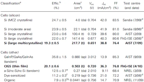
Table 1.3 Current status in the development of solar cells ……….…………..27
Table 1.4 Characteristics of PSCs DTP-based polymers……….………..29
Table 2.2 Molecular Weights and Thermal Properties of Polymers P1-P4……….….49
Table 2.3 Optical and Electrochemical Properties of Polymers P1-P4……….…52
Table 2.4 Photovoltaic Properties of Polymer Solar Cell (PSC) Devices with a Configuration of ITO/PEDOT:PSS/P1-P4:PC61BM(1:1 w/w)/Ca/Al…………...56
Table 2.5 Photovoltaic Propertiesa of Bulk-Heterojunction PSC Devices Containing Different Weight Ratios of Blended Polymers P4:PC71BM and blend film roughness by AFM measurements………..…...57
Table 3.1 Molecular Weights and Thermal Properties of Polymers (P1-P5)………....76
Table 3.2 Optical and Electrochemical Data of Polymers (P1-P5)……….……..79
Table 3.3 Electron and Hole Mobilities, Photovoltaic Properties, and Roughnesses (Rrms) of Polymers (P1-P5)……….……..……84
Table 4.1 Optical and Electrochemical Properties of Polymer PBT, Cross-Linker F, and H-Bonded Polymer Network PBT/F………...103
Table 4.2 Photovoltaic Properties and Film Roughnesses (Rrms Measured by AFM) of Bulk-Heterojunction PSC Devices Containing PBT and PBT/F with PC61BM and PC71BM in a Blending Wt. Ratio of 1:1………...106
Table 5.1 Optical and Electrochemical Properties of Polymer PBTH and Supramolecular Polymer Networks (PBTH/C and PBTH/F)……….…..132
Table 5.2 Photovoltaic Properties of Polymer PBTH and Supramolecular Polymer Networks (PBTH/C and PBTH/F).……….136
1
Chapter 1
1.1 Introduction
Energy is currently the most important problem facing mankind. The ‘‘fire age’’ in which our civilization has been based from the very beginning is approaching its end. Human beings have been burning a wide variety of materials since early times, and with the advent of carbon-based fossil fuels in the last two centuries, their combustion has become nowadays a major problem due to the huge amounts of carbon dioxide emissions produced all over the world. Moreover, nuclear energy has always been subject of intensive public discussion due to the security and health risks of nuclear power stations and the following problems with radioactive waste. Because of the resulting pollution, global warming and degradation of the planet, a new era based on non-contaminating renewable energies is currently a priority. As alternative energy sources, solar energy is regarded as one of the perfect energy resources over the last decades. The Sun, which can be considered as a giant nuclear fusion reactor, represents the most powerful source of energy available in our solar system and, therefore, its use for providing energy to our planet is among the most important challenges nowadays in science. Actually, the energy received from Sun, calculated as 120 000 TW (5% ultraviolet; 43% visible and 52% infrared), surpasses that consumed on the planet over a year by several thousand times.1 The sun has the potential to make the largest energy contribution: only one hour of sunshine (3.8×10²³ kW) is more than enough to satisfy the highest human demand for energy for an entire year (1.6×10²⁰ kW in 2005).2 Huge efforts have been invested in developing highly efficient solar energy conversion technologies and the most prospective approach is converting solar energy into
2
electricity. The emerging photovoltaic industry has been growing rapidly due to searching for green technology in recent years.
Figure 1.1 (a) World energy consumption 1990-2035 (quadrillion Btu) (b) World electricity
generation by fuel, 2007-2035 (trillion kilowatthours)
The state-of-the-art inorganic silicon solar cell technology significantly, convert 15% to 20% of the energy in sunlight to electricity, and their price has been dropping steadily. But many industry observers worry that a price floor could be near, because the cells require expensive clean-room technology to manufacture. Thin films of copper, indium, gallium, and selenium are 15% efficient and cheap, but indium is in short supply. Cadmium-telluride thin films, which rely on rare tellurium, are in much the same boat. The most widely studied organic solar cells are polymer-based solar cells using conjugated polymers. Most conjugated polymers have high absorption coefficient and high percentage of absorbed photons that can produce an excited state (>90%). There are further advantages for using the polymer-based organic solar cells. First, the photo and electronic properties of the conjugated polymers can be fine-tuned by engineering the chemical structures through advances in organic chemistry. Second, simple coating or printing processes can be used which will reduce the cost of the fabrication process. Third, the mechanical flexibility allows the development of flexible devices. Therefore, Organic solar cells
3
appear to be the highly promising and cost-effective alternative for the photovoltaic energy sector. In this context, bulk heterojunction (BHJ) photovoltaic cells (PVCs) have attracted considerable attention in recent years.
1.2 Solar Cell
A solar cell is a device that converts the energy of sunlight directly into electricity by the photovoltaic effect. The Photovoltaic effect was first observed in 1839 by French physicist Alexander-Edmond Becquerel, when he shined light onto on AgCl electrode in an electrolyte solution and a light-induced voltage was discovered.3 Forty-four years later in 1883, Fritts created the first device made from Se wafers with a power conversion efficiency (PCE) of approximately 1%.4 Since 1946, when modern junction semiconductor solar cells were patented by Ohl,5 an intensive search for highly efficient photovoltaics has been ongoing. Modern generation of solar cells was born in 1953 when at Bell Laboratories (New Jersey, USA) the first silicon solar cell was developed with a power conversion efficiency of 6%.6 After that, many different technologies and materials were developed in order to improve the performance of the device and lower their production cost.
Organic photovoltaic devices have gained a broad interest in the last few years due to their potential for large-area low-cost solar cells. The current status of solar cell is shown in Figure 1.2. The first reports on molecular thin film devices more than 30 years ago, their power conversion efficiencies have increased significantly from 0.001% in 19757 to 1% in 19868. For years the efficiency of polymer-based cells scraped along at a feeble 3% to 5%. But things have improved markedly over the past 2 years. In early April, Mitsubishi Chemical reportedly set a new
4
efficiency record producing organic solar cells with 9.2% conversion efficiency, according to
The Nikkei, a Japanese business daily.9
Figure 1.2 Terrestrial cell efficiencies measured under the global AM1.5 spectrum.9a
5
Figure 1.3 describes recent achievement from, three other companies such as Konarka Technologies in Lowell, Massachusetts; Solarmer Energy Inc. in El Monte, California; and Heliatek in Dresden, Germany are now reporting cells with efficiencies greater than 8%. Many researchers in the field are confident that the figure could soon top 10% and possibly reach 15%.9 The progresses in efficiency will possibly make them a competitive alternative to inorganic solar cells in the near future. Different concepts have been published using small molecules10, conjugated polymers11, combinations of small molecules and conjugated polymers12, or combinations of inorganic and organic materials12 as the active layer. “Active layer” refers here to the layer in which the majority of the incident light is absorbed and charges are generated. Small molecules and polymers differ in their molecular weights. Commonly, macromolecules with a molecular weight larger than 10,000 amu are called polymers, whereas lighter molecules are referred to as “oligomers” or “small molecules”. Inspired by the significant progress in solar cell efficiencies with organic materials such as organic electron donor and acceptor molecules in polymer BHJ photovoltaic cells, research have grown rapidly. This technology is relatively new, being actively researched by universities, national laboratories and several companies around the world.
1.3 Bulk-Heterojunction (BHJs) Solar Cells
1.3.1 General Device Structure of BHJs Solar Cells
BHJ solar cells are those solar cells in which semiconducting conjugated polymers or oligomers are applied as active components in the photocurrent generation and power conversion process within thin film photovoltaic devices that convert solar light into electrical energy.13 The schematic design of a bulk-heterojunction solar cell (ITO/PEDOT:PSS/Active
layer(D-6
A)/Al(cathode)) is displayed in Figure 1.4. The core of the cell is the photoactive layer, which is generally composed of a p-type electron-donor compound (D) and an n-type electron-acceptor compound (A). The photoactive layer is usually sandwiched between an indium tin oxide (ITO)-covered substrate (glass or plastic) and a reflective (aluminum) back electrode as cathode. As the ITO substrate is transparent, illumination takes place from this side of the device. The two electrodes may be further modified by the introduction of a PEDOT: PSS (poly[3,4-(ethylenedioxy)thiophene]:poly(styrene sulfonate)) coating on the ITO side. The device architecture of the photoactive layer has a strong impact on charge carrier separation and transport.
7
1.3.2 Basic Mechanistic Principles of Organic Solar Cells
Figure.1.5 shows the conversion steps of photons into separated charges as it takes place in an organic solar cell. The mechanism of energy conversion in an organic solar cell can be well explained by four fundamental steps.15
(1) Absorption of light and generation of excitons: Photoexcitation of the absorber material(s) causes the promotion of electrons from the ground state, approximated by the highest occupied molecular orbital (HOMO), to the excited state, approximated by the lowest unoccupied molecular orbital (LUMO). These photoexcitation depends upon the value of the optical absorption coefficient and on the thickness of the donor material. Then the excitons are generated which, consists of an electron and a hole paired by an energy that is smaller than the
8
energy gap between the limits of the permitted bands (LUMO and HOMO bands, respectively). The difference between two energies is called exiton binding energy which, is around 0.1-0.2 eV in organic materials. The occupation of these exited states, the LUMO by the electron, and the HOMO by the hole, is termed as nonrecombined excitons.
(2) Diffusion of the excitons: Excitons produced within a diffusion length from the D/A interface will have the chance to reach it before decaying, radiatively or not. Diffusion takes place as long as recombination process do not takes place. Forster (long range) or Dexter (between the adjacent molecules) transfers can takes place between an excited molecule.
(3) Dissociation of the excitons: If the offsets of the energy levels of the D and the A materials are higher than the exciton binding energy, excitons dissociate at the D/A interface. Excitons photogenerated in the donor side will dissociate by transferring the electron to the LUMO level of the acceptor and retaining the positive charge, while those created in the other side will transfer the hole to the HOMO of the donor while retaining the negative charge. This step leads to the formation of free charge carriers.
(4) Charge transport and charge collection: The charge carriers diffuse to the electrodes through the respective materials (electrons in the acceptor and holes in the donor). The charges reach the electrodes and are collected. For this to occur most efficiently, the following conditions must be satisfied:
(EF)cathode < (ELUMO)acceptor and (EF)anode < (ELUMO)donor.
In each of the above steps several phenomena can take place that decrease the efficiency of the global process, so that only a limited portion of the photons reaching the cell are able to generate
9
“useful” charge carriers. Thus, the optimization of each step is fundamental to extract as much energy as possible from the device.
1.4 Determination of Solar Cell Performances
Besides the insight into the overall photon-to-current conversion efficiency η (or power conversion efficiency, PCE), solar cells are further characterized by measuring the current-voltage I-V curve under illumination of a light source that mimics the sun spectrum. A typical current-voltage I-V curve of a polymer solar cell is shown in Figure 1.6. Since organic semiconductors show very low intrinsic carrier concentration, the metal-insulator-metal (MIM) model seems to be best suited to explain this characteristic. The characteristic points used to characterise a solar cell are labelled in Figure 1.6. In addition, for each of these points, the energy diagram for a single-layer cell with an indium tin oxide (ITO) anode and aluminium cathode is displayed.
1.4.1 Short Circuit Current (Isc)
The current delivered by a solar cell under zero bias is called short circuit current (Isc). In
this case, exciton dissociation and charge transport is driven by the so-called built-in potential. This can be determined by the product of photoinduced charge carrier density and the charge carrier mobility within the organic semiconductors:
Isc = neμE
Where, n is the density of charge carriers, e is the elementary charge, μ is the mobility, and E is the electrical field. Therefore, for improving the short circuit current, high mobility/low band gap materials are essential. In the MIM picture, this potential is equal to the difference in work
10
function () of the hole- and electron-collecting electrodes. For polymer solar cells, the transparent ITO electrode is often chosen (ITO = 4.7 eV) in combination with a low work
function material (Ca = 2.87 eV, Mg = 3.66 eV, Al = 4.24 eV) as counter-electrode to
achieve a high internal field.
Figure 1.6 Current (voltage) characteristics of a typical organic diode shown together with the
metal-insulator-metal (MIM) picture for the characteristic points. (a) Short circuit condition. (b) Open circuit condition. (c) Forward bias. (d) Reverse bias.12
11
1.4.2 Incident Photon-to-Current Conversion Efficiency (IPCE)
The photocurrent action spectrum of solar cells is very informative for the characterization of new materials in a device. It represents the ratio of the observed photocurrent divided by the incident photon flux as a function of the excitation wavelength and is referred to as the incident photon-to-current conversion efficiency (IPCE). The photocurrent which is normally measured is obtained outside the solar cell device; therefore, IPCE can also be named as external quantum efficiency (EQE), e.g. the current obtained outside the photovoltaic device per incoming photon: 10 The IPCE can be calculated by the following equation.
Where, I is the photocurrent in A m-2 and P is the incident light power in W m-2.
1.4.3 Open Circuit Voltage
In heterojunction solar cells, the open circuit voltage is most often simply estimated to be the difference between the donor HOMO level and the acceptor LUMO level. For example, in the case of polymer: fullerene-based solar cells, the Voc value can be estimated
by the following equation:
Voc ≈ ELUMO,Acceptor - EHOMO,Donor - 0.3 V
Where, 0.3 V represents the lost energy during the photoinduced charge-generation process. Based on this, Scharber et al. found a relationship among (1) the LUMO level of the donors, (2) the band gap of the donors, and (3) the power conversion efficiency of the devices.16 From the
12
calculation, the highest power conversion efficiency could be over 10% for single polymer:fullerene bulk-heterojunction solar cells.
1.4.4 Fill Factor
The point where the electrical power P = I × V reaches the maximum value represents the condition where the solar cell can deliver its maximum power to an external load. It is called the maximum power point. The ratio of this maximum electrical power Pmax to the product of the
short circuit current and the open circuit voltage is termed the fill factor (FF).The fill factor can be calculated by the following equation
FF =
Ideally, the fill factor should be unity, but losses due to transport and recombination result in values between 0.2–0.7 for organic photovoltaic devices. The photovoltaic power conversion efficiency (η) is then calculated for an incident light power Pin by following equation.
13
1.4.5 Organic Photovoltaic Device Architectures
The organic cells reported in the literature can be categorized by their device architecture as having single layer, bilayer, disordered bulk heterojunction; or ordered bulk heterojunction structure (Figure 1.7)
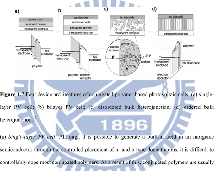
Figure 1.7 Four device architectures of conjugated polymer-based photovoltaic cells: (a)
single-layer PV cell; (b) bisingle-layer PV cell; (c) disordered bulk heterojunction; (d) ordered bulk heterojunction.17
(a) Single-layer PV cell: Although it is possible to generate a built-in field in an inorganic semiconductor through the controlled placement of n- and p-type dopant atoms, it is difficult to controllably dope most conjugated polymers. As a result of this, conjugated polymers are usually made as pure as is practically possible and can effectively be considered to be intrinsic semiconductors. Generating built-in electric fields within a film in the dark requires sandwiching the polymer between electrodes with varying work functions or incorporating interfaces with a second semiconductor into the device structure.18 In single-layer conjugated polymer PV cells, the sign and magnitude of Voc could at least be partially attributed to an electrode work-function
14
difference. Although single-layer PV cells tend to produce a reasonable Voc, their photocurrent is
typically very low.19
(b) Bilayer PV cell: C. W. Tang in 1985 discovered that, by making two-layer PV cells with organic semiconductors that have offset energy bands, the external quantum efficiency of PV cells could be improved to 15% at the wavelength of maximum absorption.20 The improved efficiency resulted from exciton dissociation at the interface between the two semiconductors. Excitons generated within a few nanometers of the heterojunction could diffuse to the interface and undergo forward electron or hole transfer. This process of forward charge transfer led to the spatial separation of the electron and hole, thereby preventing direct recombination and allowing the transport of electrons to one electrode and holes to the other. Because there were essentially no minority free carriers in the undoped semiconductors, there was little chance of carrier recombination once the charges moved away from the interface, despite the long transit times to the electrodes. Sariciftci et al. first applied this two-layer technique to a conjugated polymer PV cell by evaporating C60 on top of a spin-cast MEH-PPV layer.21 However, in the organic PV cell,
the excitons in these materials need to be generated near the interface for dissociation to occur before recombination. The exciton diffusion length in several different conjugated polymers has subsequently been measured to be 4−20 nm.22 Because the exciton diffusion length in a conjugated polymer is typically less than the absorption length of the material ( 100 nm), the EQE of a bilayer device made with a conjugated polymer and another semiconductor is ultimately limited by the number of photons that can be absorbed within an exciton diffusion length of the interface.
15
(c) Disordered bulk heterojunction: To address the problem of limited exciton diffusion length in conjugated polymers, Yu et al.23 and Halls et al.24 independently intermixed two conjugated polymers with offset energy levels so that all excitons would be formed near an interface. They observed that the photoluminescence from each of the polymers was quenched. This implied that the excitons generated on one polymer within the film reached an interface with the other polymer and dissociated before recombining. This device structure, called a bulk heterojunction, provided a route by which nearly all photogenerated excitons in the film could be split into free carriers.
(d) Ordered bulk heterojunction: In all of the bulk heterojunction devices that we have described above, the conjugated polymer and electron acceptor have been randomly interspersed throughout the film. The randomly distributed interface between the two semiconductors can lead to incomplete PL quenching in the conjugated polymer in regions of the polymer that are more than an exciton diffusion length away from an acceptor. For these reasons, some have sought to create well-ordered conjugated polymer−electron acceptor films. In an ideal device structure, every exciton formed on the conjugated polymer will be within a diffusion length of an electron acceptor, although quantitative modeling has pointed out that some light emission will still occur in the polymer even if this is the case.25 Polymeric bulk heterojunction devices, whose photoactive layer is composed of a blend of bicontinuous and interpenetrating donor and acceptor, can maximize interfacial area between the donor and the acceptor. In addition, these devices can be processed in solution, such as spin-coating or roll-to-roll printing, thereby contributing several attractive advantages such as low-cost, lightweight, and flexible devices.
16
1.4.6 Comparison between Organic and Inorganic Solar Cell
The mechanism underneath the operation of a polymer (or an organic) solar cell exhibits, of course, many similarities with that of inorganic cells, but also some distinctions, arising from a few important different characteristics of the materials involved:
(1) While inorganic semiconductors exhibit a band structure, organic semiconductors possess discrete energy levels (molecular orbitals). Nevertheless, the term “bandgap” is often improperly used for organic semiconductors.
(2) In solar cells based on inorganic semiconductors such as silicon, the absorbed photons lead to the direct creation of free charge carriers. In contrast, in organic semiconductors based on π-conjugated systems because of the low dielectric constant of these materials, light absorption leads to the creation of excitons, strongly coulombically bound electron-hole pairs. In organic heterojunctions, the driving force for exciton dissociation is provided by the energy offset between the molecular orbitals of the donor and acceptor. Exciton dissociation into free charge carriers thus represents a key process that imposes one of the major limitations to the power conversion efficiency of organic solar cells.
(c) When a bound hole-electron pair (exciton) is generated in an inorganic semiconductor, its immediate dissociation is observed. Excitons in organic semiconductors are tightly bound (binding energy of around 0.3−0.5 eV) and dissociation must be promoted in some way avoiding radiative recombination.
(d) Compared to inorganics, charge carrier mobilities in organic semiconductors are very low.
17
1.5 Literature Survey of Polymer Solar Cell Materials
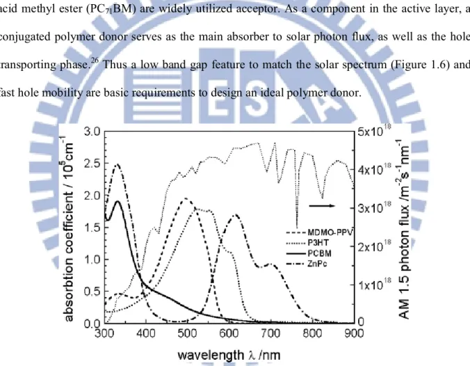
In a typical polymeric BHJ PVC, the photoactive blend layer, sandwiched between an indium tin oxide (ITO) positive electrode and a metal negative electrode, may be composed of a low band gap conjugated polymer donor and a soluble nanosized acceptor.11, 15 A fullerene derivative, [6,6]- phenyl-C61-butyric acid methyl ester (PC61BM) or [6,6]- phenyl-C71-butyric
acid methyl ester (PC71BM) are widely utilized acceptor. As a component in the active layer, a
conjugated polymer donor serves as the main absorber to solar photon flux, as well as the hole transporting phase.26 Thus a low band gap feature to match the solar spectrum (Figure 1.6) and fast hole mobility are basic requirements to design an ideal polymer donor.
Figure 1.8 Absorption coefficients of films of commonly used materials in comparison with the
18
1.5.1 Design Considerations for Low Band Gap Polymers
In recent days, interests in the design and synthesis of conjugated polymers have been increased for the applications of electronic and photonic devices. It remains a key challenge to synthesize ideal low band gap (LBG) polymers with high intrinsic conductivities to develop their potential applications in highly efficient BHJ solar cells. Concerning the band gaps of LBG polymers, the following factors should be taken into the account: intra-chain charge transfers, bond-length alternation, aromaticity, substituents effects, intermolecular interactions, and π-conjugation length etc.28, 29
The low band gap copolymers reported are often based on thiophene but other electron rich aromatic units such as pyrrole are also found. Identical for these copolymers are the alternation between electron donor (electron rich) and electron acceptor (electron deficient) units. The high energy level for the HOMO of the donor and the low energy level for the LUMO of the acceptor results in a lower band gap due to an intra-chain charge transfer from donor to acceptor.29 Planarity along the aromatic backbone results in a low band gap, due to a high degree of delocalization of the π-electrons. The alternation between single and double bonds along the polymer chain has a tendency to increase the band gap. A reduction of the difference in bond length alternation is achieved by the alternation of donor and acceptor units along the conjugated polymer chain thus lowering the band gap. As described interactions between acceptor and donor enhance double bond character between the repeating units, this stabilizes the quinoid form of e.g. benzo-bis(thiadiazole) (Figure 1.7) formed within the polymer backbone, and hence a reduction in band gap is achieved.30
19
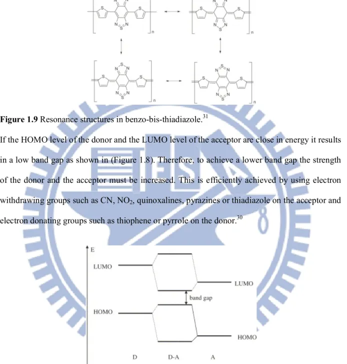
Figure 1.9 Resonance structures in benzo-bis-thiadiazole.31
If the HOMO level of the donor and the LUMO level of the acceptor are close in energy it results in a low band gap as shown in (Figure 1.8). Therefore, to achieve a lower band gap the strength of the donor and the acceptor must be increased. This is efficiently achieved by using electron withdrawing groups such as CN, NO2, quinoxalines, pyrazines or thiadiazole on the acceptor and
electron donating groups such as thiophene or pyrrole on the donor.30
Figure 1.10 Alternating donor–acceptor units lower the effective band gap by orbital mixing. 31
In order to increase the PCE in BHJ solar cells, some important characteristics of LBG polymers need to be dealt, such as: (i) a more favorable overlap of the absorption spectrum of the
20
active layer with the solar emission32 – Many classes of LBG polymers with the absorption edges extended into the near-infrared regions have been synthesized and investigated.33 (ii) a better charge carrier mobility34 – This can be improved by optimization of intra-chain ordering (co-planarity and conjugation length) and inter-chain stacking, which often can be increased upon annealing the BHJ solar cell devices.35 (iii) an optimized relative positions of the energy levels of the electron donors and acceptors36 – The maximization of the open circuit voltage (Voc)
is correlated to have more efficient charge separation between electron-donor polymers and electron-acceptor PCBM. For this purpose, the donor polymer should exhibit a band gap between 1.2 and 1.9 eV, which corresponds to a HOMO energy level between -5.8 and -5.2 eV and LUMO energy level between -4.0 and -3.8 eV.37 In order to achieve higher efficiencies of BHJ solar cell devices, the difference of the LUMO levels between donor polymer and acceptor PCBM needs to be at least 0.3 eV.38 Otherwise, the driving force for charge separation will be decreased, and also Voc will be reduced by raising the HOMO level of the donor polymer.
Therefore, in order to synthesize LBG polymers, the design rules described above suggest that the optimization of HOMO and LUMO levels of LBG polymers is the most promising strategy to develop BHJ solar cells with high efficiencies. However, it is difficult to synthesize the LBG polymers with all three properties like broad absorption spectra, high carrier mobilities, and appropriate molecular energy levels.
21
1.5.2 Polymer Solar Cell Materials
Generally, organic materials having delocalized π electrons, absorbing sunlight, creating photo generated charge carriers and transporting these charge carriers can be used for fabrication of polymer solar cells. These materials are classified to the electron donors and the electron acceptors.
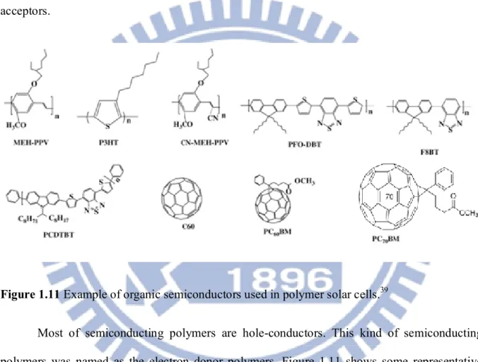
Figure 1.11 Example of organic semiconductors used in polymer solar cells.39
Most of semiconducting polymers are hole-conductors. This kind of semiconducting polymers was named as the electron donor polymers. Figure 1.11 shows some representative semiconducting polymers. Four important representatives of electron donor polymers are MEH-PPV, P3HT, PFO-DBT and PCDTBT. The electron acceptor polymers like CN-MEH-MEH-PPV, F8TB, and small molecules, C60 and soluble derivatives of C60 and C70, namely PC60BM and
PC70BM, are also shown in Figure 1.11. Fullerenes are considered to be the best electron
22
between the donor polymers and fullerenes; (ii) fullerenes exhibited high mobility, for example, PC60BM shown electron mobility up to 1 cm2 V-1 s-1 measured by field effect transistors; (iii)
fullerenes shown a better phase segregation in the blend film.40
Dialkoxy-substituted poly(para-phenylene vinylene)s (PPVs), for example, poly[2-methoxy-5-(2-ethyl-hexyloxy)- 1,4-phenylene vinylene] (MEH-PPV) and poly[2-methoxy-5- (3’,7’-dimethyloctyloxy)-1,4-phenylene vinylene] (MDMOPPV) shows strong absorption in the visible light band. Notable PCE values of 2-3% have been reproducibly achieved.41, 42
1.5.3 Various Low-band-gap polymers for solar cells
The efficient BHJ PSC device architectures were obtained by using an active layer of poly (3-hexylthiophene) (P3HT) as an electron donor and PC61BM as an electron acceptor,
which were able to reach PCE values up to 5%.43 The main disadvantage of P3HT is appreciably wide band gap (1.9 eV) and able to absorb only 22% of influx from solar spectrum because the maximum photon fluxes from the sun to earth surface is ca. 1.8 eV (i.e., 700 nm). In such conjugated polymers, electron-donating groups and electron-withdrawing groups are substituted alternatively in the polymer backbones to lower HOMO energy levels.44 Therefore, the molecular design of D-A alternating architectures in polymer backbones have received considerable attention to organic chemists for the developments and applications of new low band gap conjugated polymers in photovoltaic devices. Followings are new class of LBG materials has attracted much interest from the scientific community with their promising results for commercial applications.
23
Figure 1.12 Chemical structures of 2,7-Carbazole containing LBG polymers.
Polycarbazoles (i.e. polyvinylcarbazoles) were first reported as photoconductive materials in photocopiers. Since then, different families of poly(carbazole)s have been reported in the literature such as poly(3,6-carbazole)s, poly(1,8-carbazole)s, and poly(2,7-carbazole)s. This last class of materials was found to exhibit interesting features that make these polymers attractive for photovoltaic applications. Indeed, poly (2,7-carbazole)s possess low HOMO energy levels which lead to air-stable materials and to high open circuit voltage (Voc). Upon structure
modifications, those materials can be easily fine tuned to match the optimal solar spectra emission. The main reasons for using a carbazole unit over a fluorene unit is that they are reported to have better hole transporting properties with respect to the fluorene unit, while maintaining the stability.45 They can also exhibit good hole mobility values.Also, the 2,7-carbazole ring is fully aromatic, which provides a better chemical stability. Figure 1.12 and
24
Table 1.1 shows chemical structures of some 2,7- carbazole containing LBG polymers for PSC applications.
Table 1.1 Characteristics of PSCs based on 2,7- carbazole derivatives.
25
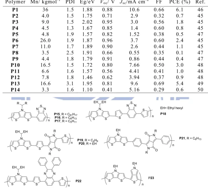
Table 1.2 Characteristics of PSCs DTP-based polymers.
An enhanced intermolecular π-stacking, long-range order, and solution processable electron donating dithieno[3,2-b:2’,3’-d]pyrroles (DTP) unit one kind of electron rich building block containing fused thiophene units, offer great processabilities by attaching various alkyl chains to N-substituents of the pyrrole rings without affecting their conjugation lengths can be co-polymerized with various electron-deficient units to generate LBG polymers for PSC applications. Figure 1.13 and Table 1.2 demonstrates DTP containing LBG polymer and their properties.
Figure 1.14 and Table 1.3 are some of the benzodithiophene ans dithieneo silole containing polymer structures, developed in recent years have seen a dramatic improvement in the efficiency of polymer solar cells. Maximizing the open-circuit voltage in low-band gap polymers is one of the critical factors towards enabling high-efficiency solar cells. Study of the relation between open-circuit voltage and the energy levels of the donor/acceptor in bulk heterojunction polymer solar cells has stimulated interest in modifying the open-circuit voltage by tuning the energy levels of polymers. Recently, by tuning the open-circuit voltage of polymer
26
solar cells based on the structure of a LBG polymer P27, yielded power conversion efficiency as high as 7.7%, as certified by the National Renewable Energy Laboratory.
Figure 1.14 Chemical structures of benzodithiophene and dithienosilole containing polymers.
27
Various electron-accepting moieties reported so far, such as benzothiadiazole,45 thiazole,62 triazole,59 and quinoxaline,45 to manipulate the HOMO level of polymers. Thiazole unit is one of the five-membered azaheterocycles with electron deficient characteristics, which contains an electron-withdrawing imine (–C=N) in place of the carbon atom at the 3-position of thiophene.62,63 Moreover, the thiazole-based polymers showed high oxidative stabilities which minimized the HOMO energy levels and to induce the high Voc values. Followings are some
bithazole containing polymer reported in recent years. Figure 1.15 and Table 1.4 are few examples of bithazole derivative containing LBG polymers for solar cells.
28
29
1.5.4 Supramolecular Hydrogen-Bonded Polymers for Organic Solar Cells
Nanostructured materials with tailor-made properties and functions can be developed by exploiting the supramolecular approach through molecular recognition.68 In fact, the hierarchical self-assembly of multivalent molecular modules through the concerted action of multiple non-covalent interactions represents a very powerful approach as it makes possible the simultaneous organization of various molecular systems into intrinsically defect-free 2D architecture featuring a long-range order.69
30
Hitherto a large variety of interactions have been employed in order to hold together molecular modules forming targeted self-assembled mono-component architectures at surfaces including dipolar forces,70 coordination bonds,71 metal bonds,72 H-bonds,73 and more recently covalent interactions.11 Among the proposed approaches, the use of H-bonding is very promising since this type of interaction features very high directionality and selectivity, along with a reversible character, providing access to a vast variety of sophisticated functional assemblies and materials barely accessible through conventional covalent synthesis.73
The design of supramolecular D-A systems was recognized as a promising strategy via the charge-transfer processes between donor and acceptor units.73 Würthner, Schenning, and Meijer reported well-defined mesoscopic assemblies by using complementary H-bonded moieties of perylene bisimide and melamine derivatives. Meijer et al. reported a PCE value of 0.25% for the polymer solar cell (PSC) device by utilizing a main-chain H-bonded polymer P47 containing oligo(p-phenylene vinyene) and ureido-pyrimidinone units (as H-bonded groups).74 Small molecules and their polymer analogues have attracted exceptional attentions in the recent days owing to their corresponding advantages, including high purities and (hole and electron) mobilities for small molecules, and easy processing capabilities and low costs for polymers.75 Therefore, one of the attractive approaches is to achieve advanced π-conjugated materials by the combination of both small molecular and polymeric designs through supramolecular architectures. Figure 1.16 demonstrates some of supramolecular hydrogen bonded cross-linking polymers for solar cell applications. Cross-linking polymer P48/S3 and P49/D2 shows higher PCE of 0.50 and 0.31% among the above serie of cross-linking polymers.76
31
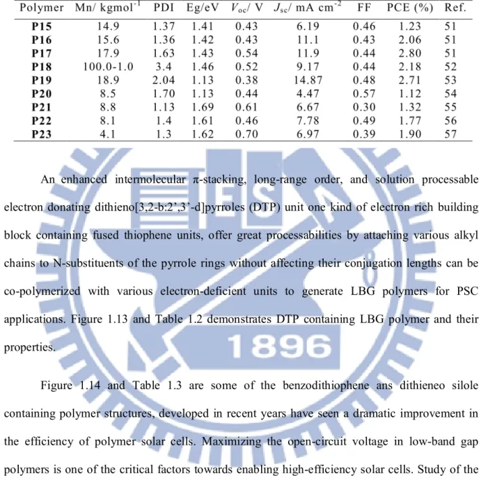
1.5.5 Characterization of Active Materials for Polymer Solar Cells
The molecular design of D/A pairs for high efficiency PSC has to meet a lot of optoelectronic requirements, other than an excellent processability from solution, very high chemical purity, etc. To this end, an extensive characterization of the newly synthesized materials is required, involving multidisciplinary expertise (Figure 1.17), to assess their potentials as promising donors or acceptors for polymer solar cells. Chemists are making a great effort in the direction of energy level engineering and a variety of fullerene derivatives and p-type conjugated polymers (vide infra) have been proposed as functional materials toward high efficiency PSC.
Figure 1.17 Basic investigation techniques required for an extended characterization of active
32
1.6 Objective and Outlines of this Thesis
The main objective of this dissertation is to construct the donor-acceptor polymers or supramolecular polymer networks by mixing proper molar ratio of polymer and conjugated cross-linkers and further to study their performances in BHJ PSCs as electron donors with fullerene derivatives as electron acceptors.
In wide bandgap polymers there is a disadvantage of less light harvesting from the solar spectrum range though the larger gap between the HOMO and the LUMO on the polymers provide an opportunity to increase the open circuit voltages. In order to increase the Voc while
holding the band gap constant, the energy levels of both the HOMO and LUMO of the conjugated polymer must be decreased simultaneously. Thus, electron-withdrawing groups would need to be added to the polymer. 58 Conjugated polymers having D-A architectures have been extensively studied by utilizing fused heterocyclic electron rich segments, such as carbazole,45-48 cyclopentadithiophene,67 dithienopyrrole,52-54 dithienosilole,60 fluorene,63 and benzodithiophene58, 59 as an electron donating building block for PSCs and organic field effect transistors (OFETs). Owing to the easy modulations of physical properties, it has been proven that, 2,7-carbazole derivatives are the excellent potential donor candidates for BHJ solar cells.45 Using 2,7-carbazole and benzothiadiazole with improving absorption characteristics and charge-carrier mobilities, Heeger et al. reported an ever high PSC device containing PCDTBT with a PCE value of 6.1% and an internal quantum efficiency approaching ca. 100%.46 The five-membered heterocyclic electron deficient moiety, i.e., thiazole, induces larger π–π stacking and higher co-planarity65-67 in D-A polymers so as to have a stronger tendency to self-assemble into stacked solid structures, which not only minimize steric hindrances but also provide extended
33
conjugation lengths. Introduction of thiazole units with electron-withdrawing imine nitrogen (– C=N) generally enhances the electron-accepting (n-doping) properties of the D-A polymers.65 Moreover, thiazole-based polymers exhibit high oxidative stabilities which favor the polymers to lower its HOMO energy level and thus to increase their open circuit voltages.65
In chapter 2 copolymers consisting of a planar 2,7-carbazole moiety with conducting thiophene (thiophene or bithiophene) as electron-donating segments and bithiazole derivatives as electron-accepting segments, were synthesized by Pd(0)-catalyzed Stille coupling polymerization. The effects of electron deficient bithiazole units on the thermal, optical, electrochemical, and photovoltaic properties of these LBG copolymers were investigated.
DTPs, one kind of electron rich building block containing fused thiophene units, offer great processabilities by attaching various alkyl chains to N-substituents of the pyrrole rings without affecting their conjugation lengths.78 However, due to high values of HOMO levels in DTP-based polymers, they showed relatively low Voc values (less then 0.6 V) and thus to induce
low PCE values.51-56, This problem is expected to be solved by using various electron-deficient units to manipulate their HOMO energy levels.57, 79 In Chapter 3, a series of alternative D-A conjugated DTP-based polymers containing the electron-rich DTP block (with a minimum branched alkyl chain length) and electron-deficient bithiazole along with various conducting thiophene lengths were synthesized via Suzuki coupling polymerization. The manipulation of optical, electrochemical, and photovoltaic properties by copolymerizing with electron-deficient bithiazole derivatives were discussed.
During the past decade, semi-conducting polymers containing supramolecular structures, including hydrogen-bonds (H-bonds), are one of the key targets for sensors and optoelectronic
34
devices.80 Owing to the self-assembly behavior, high specificity, and directionality of H-bonds, 69 well-defined nanostructures and mesoscopic assemblies are generated by utilizing complementary hydrogen-bonding concept. Due to self-assembly between complementary molecular components, various kinds of non-covalent interactions, such as hydrogen-bonds (H-bonds),73 ionic forces,74 and metal-coordinations,73 can give rise to unique properties, which are not possessed by their individual components. Small molecules and their polymer analogues have attracted exceptional attentions in the recent days owing to their corresponding advantages, including high purities and (hole and electron) mobilities for small molecules, and easy processing capabilities and low costs for polymers. 75 Consequently, one of the attractive approaches is to achieve advanced π-conjugated materials by the combination of both small molecular and polymeric designs through supramolecular architectures, so the H-bonded polymer networks are explored.76
In chapter 4, we could tune molecular energy levels, morphologies, and device proferemances by a new and straight-forward approach to introducing multiple H-bonded supramolecular structures. The broader light absorption (an extra blue absorption from H-bonded crosslinker F and the red-shifted absorption from H-bonded main-chain polymer PBT), lower HOMO level (to have a higher Voc value), higher hole mobility, larger crystallinity, and better
morphorlogy in H-bonded polymer network PBT/F induces better photovoltaic properties than that containing polymer PBT were discussed.
In chapter 5 we synthesized a conjugated main-chain polymer PBTH, in which the melamine pendants can be H-bonded with complementary uracil-based conjugated cross-linkers


![HPSH [ 分子間作用力 - 氫鍵 ]](data:image/gif;base64,R0lGODlhAQABAIAAAP///wAAACH5BAEAAAAALAAAAAABAAEAAAICRAEAOw==)