DOI 10.1007/s00170-004-2060-4 O R I G I N A L A R T I C L E
Chun-Fong You · Chien-Hao Lin
Java-based computer-aided process planning
Received: 10 September 2003 / Accepted: 8 December 2003 / Published online: 3 August 2005 ©Springer-Verlag London Limited 2005
Abstract This investigation addresses distributed environments for computer-aided process planning (CAPP) over a network. The Java 2 Enterprise Edition (J2EE) standard using Java is applied to implement cross-platform and distributed computing architecture, thus reducing the system loading during manufac-turing process planning. The product-oriented standard, standard exchange of product (STEP), model data is applied to define a robust data model that associates product, shape, and feature definitions and provides the mechanisms for data exchange, shar-ing, and integration with other engineering systems, such as computer-aided design (CAD) and computer-aided manufactur-ing (CAM). STEP AP224 is engaged to define the machinmanufactur-ing features of machined products in the proposed CAPP system. The life cycle of a product from design to sale, and especially the period of manufacturing, can be greatly shortened; the cost of manufacturing can be reduced and the quality of the product can be improved using the proposed CAPP system.
Keywords AP224· CAPP · Product life cycle · STEP
1 Introduction
Computer software for manufacturing engineering, such as computer-aided design (CAD), computer-aided manufacturing (CAM), and computer-aided engineering (CAE), are essential in the present manufacturing environment. Such software is a sub-stitute for drawing and analysis by hand, and reduces the life cycle of products from design to sale, using the computer power of personal computer or workstation.
This work proposes a web-based computer-aided process planning (CAPP) system to bridge the calculated and managed C.-F. You (u) · C.-H. Lin
Department of Mechanical Engineering, National Taiwan University,
Taipei, Taiwan E-mail: [email protected] Fax: +886-2-23631755
data from CAD and CAM systems. With the assistance of algo-rithms and artificially intelligent computer manipulations, manu-facturing engineers can plan processes, and select manumanu-facturing machines and tools. The proposed system applies a three-tired architecture and distributed technology over a network to dis-tribute computing tasks to individual computers. AP224 [1] in standard exchange of product (STEP), ISO 10303, is used to de-fine a data model of manufacturing features in the system, to ensure integrity, maintenance, extensibility of the exchange and sharing of data.
2 Review
Since 1970, research into algorithms and artificially intelligent computer-aided process planning has greatly assisted manufac-turing engineers. The approaches in this area are classified as either variant or generative.
Based on group technology and developed in the late 1970s, the variant approach groups working material and assigns stan-dard processes to the shapes and manufacturing properties with similar conditions. A unique GT code and its standard manufac-turing process can be determined by properties when a product model is made. The specified processes can be modified when the manufacturing engineer needs to update the process informa-tion. MI-PLAN [2], CAPP [3], and XCUT [4] use this approach. This approach is suited to enterprise, involving stable manufac-turing process and manufacmanufac-turing products that vary only a little. The advantage of this approach is the ease of maintenance, but the shortcoming is the lack of an on-time calculation of manu-facturing process. Manual input is required to establish the mass data of the manufacturing processes.
The generative approach, without manual input, can auto-matically generate corresponding manufacturing processes using a design model of workpieces. Earlier developments of this ap-proach adopted decision-making to determine the manufactur-ing process and use GT code or special descriptive language to define workpieces. Later development focused on the use of feature-definition to define the product models and then feed
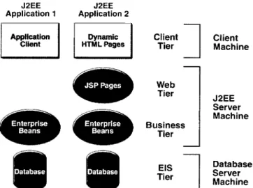
Fig. 1. Multi-tiered distributed application model using J2EE
a complete process plan to the CAPP system. The drawback of this approach is the difficulty of extracting features. Feature-based design is now the major area of research in this approach to solve this problem. It provides built-in features and corres-ponding manufacturing processes to help engineers define manu-facturing features and thus avoid feature-extraction problems. EXCAP [5], OOPPS [6], CPP [7] and the algorithms of the pro-posed CAPP system adopt this approach.
Web-based technology provides a networking environment for engineering computing and bridges between various systems and platforms in the field of distributed computing. This work adopts Java language to migrate the CAPP system to a Web-based environment and thus distribute the operations of CAPP to various computer systems to reduce the computation load-ing. Through Java Virtual Machine (JVM), the class compiled as Byte code is accessed and executed. The multi-tiered distributed application model, using J2EE [8] proposed by Sun, Inc., is used to define the system architecture over the network. Based on the model, the proposed CAPP system consists of three layers, as illustrated in Fig. 1. They are client, J2EE server, and database server layers.
STEP AP224 is used to define the manufacturing features used in the proposed CAPP systems. It defines process plan-ning, cutting tools and tool parameters. AP224 completely de-fines manufacturing processes for a product that requires twelve items, including manufacturing features, definition items, and other properties. The data items are the definitions of manufac-turing features and features’ defining items. The information, which cannot be imported from CAD systems, is beyond the scope of this paper.
3 Proposed approach
The proposed system can be discussed in two parts, address-ing CAPP data-modeladdress-ing usaddress-ing STEP AP224, and CAPP system architecture based on J2EE. The former focuses on the
appli-cation of AP224 to establish the standardized database schema for the CAPP system and access as a service to enable access to feature information in the server. The latter part focuses on applying J2EE three-layered architecture to the configured pro-posed CAPP system over a computer network.
3.1 CAPP data modeling using STEP AP224
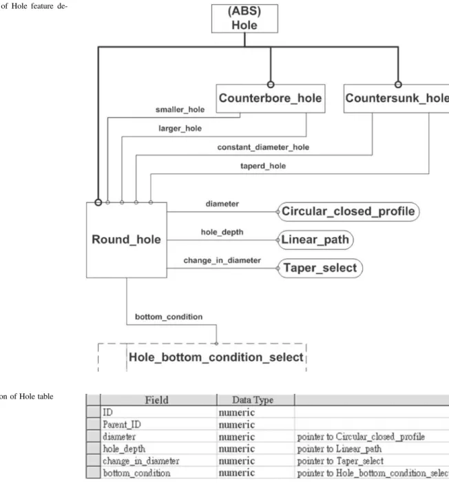
The application reference model (ARM), a data model defined in STEP AP224 is used to model the data schema required by the proposed CAPP system. The application interpreted model (AIM), a data models in AP224, is then used to export or import the exchange file, based on STEP Part 21. EXPRESS definition in ARM models is translated into the data schema of rela-tional databases that are used in the CAPP system. Consider, for example, the round_hole feature: it is inherited from the hole fea-ture as shown in Fig. 2 and has four attributes, including diam-eter, hole_depth, bottom_condition, and change_in_diameter. These attribute types are Circular_closed_profile, Linear_path, Taper_select, and Hole_bottom_condition_select and depend on four supporting tables. The Round_hole table must consist of four fields of integers to store the corresponding ID numbers of these attributes, as illustrated in Fig. 3. All of the relation-ships within these tables should be defined, and their integrity maintained, by the CAPP system.
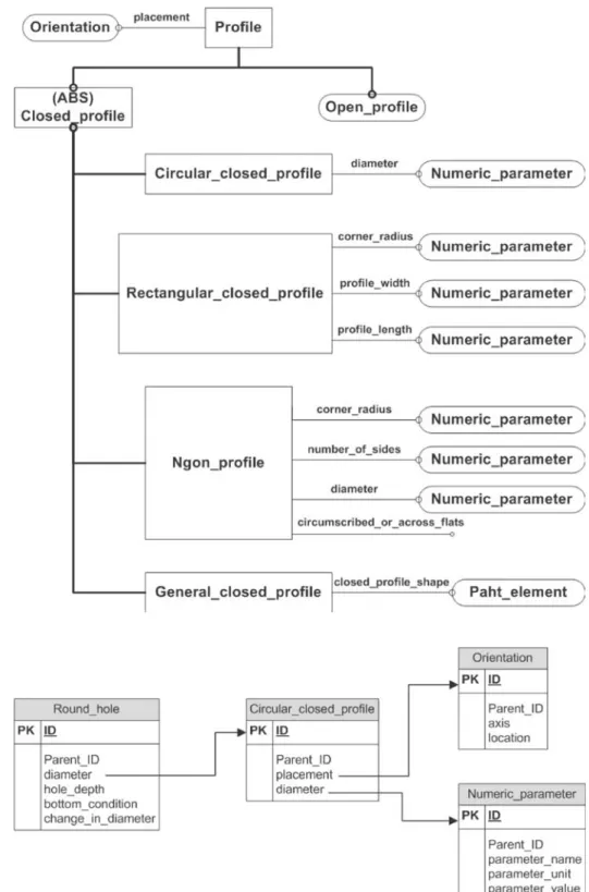
The first attribute, diameter, can be represented as an instance of Circular_closed_profile whose EXPRESS-G model is illus-trated in Fig. 4. It is inherited from the Profile feature and has two attributes: placement and diameter. By the same approach, the definition of the feature is translated into a relational database schema that contains the association relationship. Figure 5 shows the well-defined relationships of the Round_hole feature.
3.2 CAPP system architecture based on J2EE
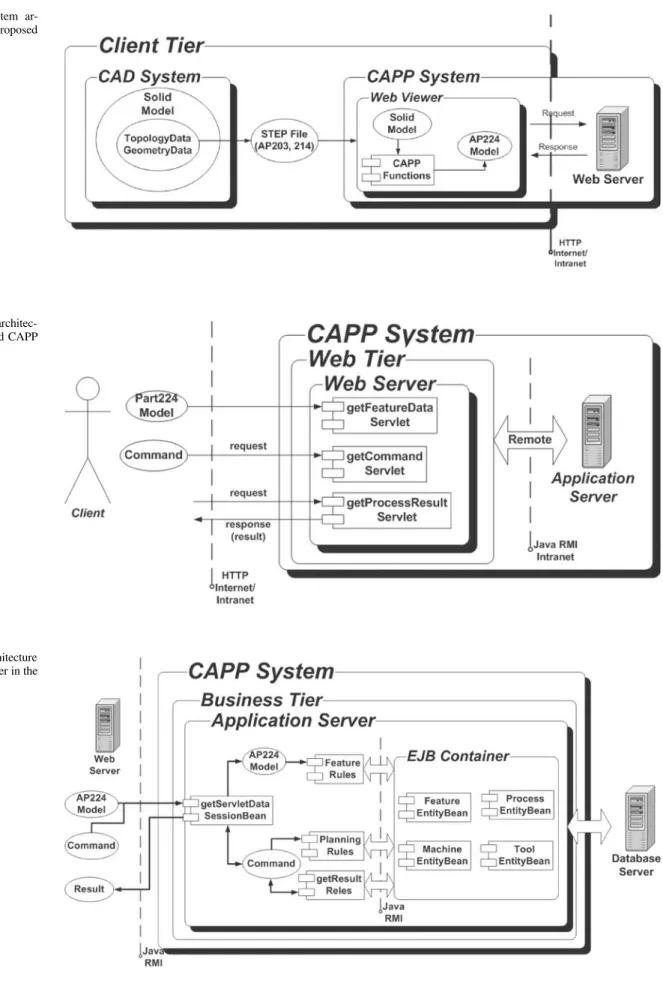
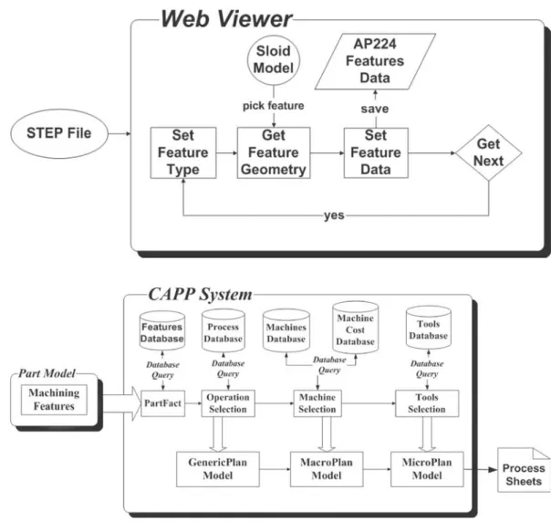
The CAPP system proposed in this study consists of three layers: client, J2EE server, and database server. The client layer adopts Java-based STEP Viewer developed by Solid-Model Lab., to pro-vide users with thin-client features. A user can use the viewer to import CAD files based on AP214, render 3D models, and de-fine manufacturing features based on AP224. The J2EE server layer supports the service for calculating manufacturing process-planning, according to the request from client layer. The database server layer handles the data models defined in preceding sec-tion. Figure 6 depicts the overall architecture of system. The sys-tem is used to import the STEP file exported from CAD syssys-tems and render the 3D model, using the Java-based STEP Viewer. The features of the 3D models can be manually defined in the viewer. When a manufacturing process is required, the feature is marshaled to a server, wrapped in a request; the response from the server is obtained and the UI (User Interface) is updated by adding manufacturing process information.
The server layers are coded using Java Servlet technology de-fined in J2EE. Figure 7 depicts the architecture. The Web server acts as a switcher between the client and the application server.
Fig. 2. Data model of Hole feature de-fined in AP224
Fig. 3. Field definition of Hole table
According to the information sent from the client to the server, the Servlet applications dispatch commands to various Enter-prise Java Beans (EJBs), including feature data, command execu-tion, and process-planning result Servlet to accomplish manufac-turing process planning.
The algorithms for planning manufacturing process, ma-chine, and selecting tools in the proposed system, are all im-plemented in separate EJB components that reside in the appli-cation servers defined in J2EE. All these components are de-ployed to different application server of different server over a network, to distribute system loading and shorten the planning time, as shown in Fig. 8. A SessionBean is used to communicate with Servlet applications, and dispatches commands to different Servlet applications. The EntityBean that resides in EJB
con-tainer is then called to store the results of the process-planning through a SessionBean. The result is then returned to the appli-cation server.
4 Implementation and samples
Manufacturing process-planning using the proposed system is demonstrated. The 3D product model of the workpiece is gener-ated using the CATIA CAD system, and exported to a STEP file based on AP214. The Java-based STEP Viewer is then launched to open the STEP-based model to define manufacturing features based on AP224, as illustrated in Fig. 6. The feature definition of the system is based on the research into feature-recognition and
Fig. 4. Data model for Profile feature de-fined in AP224
Fig. 5. Table relationship for Round_hole feature
feature-based design [9, 10] and also supports from the automatic feature recognition developed by this Solid Model Lab [11]. A feature based on AP224 can be selected and defined by setting its parameters and shape-definition through a Java-based viewer. Figure 9 illustrates the process of defining a manufacturing fea-ture in the system.
A user can then plan a manufacturing process after defin-ing the manufacturdefin-ing features of the 3D model. Four mod-ules, including part fact, operation selection, machine selection, and tools selection modules, as illustrated in Fig. 10, describes an algorithm for planning manufacturing process. The part fact module is used to obtain the required information concerning
Fig. 6. Overall system ar-chitecture of the proposed CAPP system
Fig. 7. Web server architec-ture of the proposed CAPP system
Fig. 8. System architecture for application server in the CAPP system
Fig. 9. Process of defining manufacturing feature in the proposed system
Fig. 10. Algorithms of manu-facturing process planning used in the proposed system
machined shape and the tolerance for process planning. The op-eration selection module is used to access feature classification and machining properties, support classification, and determine the sequence required by the specific tolerance and surface area. The machine selection module accepts the information from the two modules before it calculates a suitable machine whose cost is relatively low. The tools model, similar with machine selec-tion module, calculates the suitable tool whose cost is relatively the least through EntityBean for tools. The result of process plan-ning is stored in the to database to be accessed by clients. All of these modules are coded as individual EJB components. The corresponding EntityBean can access the database.
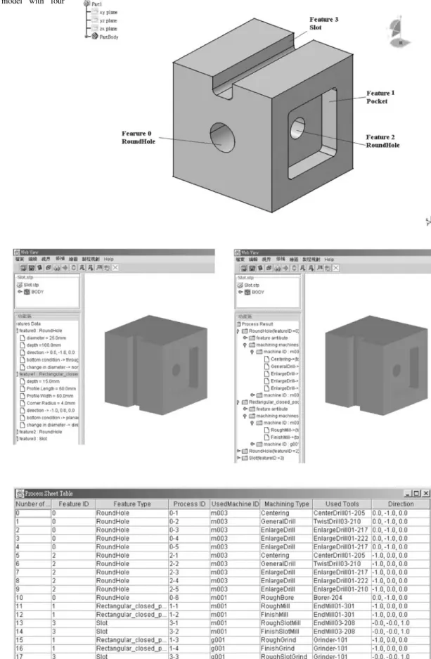
Figure 11 illustrates the sample model used to demon-strate the proposed CAPP. The working material is a 100× 100× 100 mm3block with four features, including two through holes whose dimensions areφ 18 mm × d 85 mm and φ25 mm ×
d 100 mm, one pocket whose dimensions arew 60 mm×l 60 mm
×d 15 mm, and one slot whose dimensions are w 20 mm ×
l 100 mm× d 15 mm. The 3D model is generated using the
CATIA CAD system and exported as a STEP file. The fea-ture information created in CATIA system may be lost since
the information concerning the feature is not supported in STEP AP214.
A user uses the Java-based STEP Viewer to import the STEP file and manually defines STEP-based manufacturing features with the help of the system, as illustrated in Fig. 12a. The pro-cess planning can be triggered to pass the feature information to the server via various modules. The GUI of the viewer is then updated to display the resulting process plan, as illustrated in Fig. 12b. The result is represented as a feature tree and the order is arranged according to the sequence of manufacturing features. The selection of machine, tool, and operation selection is ex-panded beyond that the original feature tree.
Another result of the proposed system is the manufacturing process report, as shown in Fig. 13. The manufacturing process sequence and operations can be illustrated with the support of this report. The report indicates that the process should be started by using a vertical miller, whose ID is m003, to drill the round hole, whose feature IDs are 0 and 2. The manufacturing fea-ture whose ID is 0, should be generated before the other feafea-ture whose ID is 2. The second machine engaged in the manufactur-ing process is a vertical miller whose ID is m001, which drills
Fig. 11. The 3D sample model with four features
Fig. 12a,b. GUI of Java-based STEP Viewer with the sample workpiece. a Original feature tree b Feature tree with process planning
Fig. 13. Manufacturing pro-cess planning report of the sample workpiece
features whose IDs are 0 and 2, and then mills the features, whose IDs are 1 and 3. The last engaged machine is a grinding machine to grind the pocket and slot features.
5 Conclusion
The Java-based CAPP system proposed in this study implements the STEP AP224 data model to bridge CAD and CAM systems and thereby maintain the relationships among product, shape and feature definitions. The product-oriented data model defined in STEP can ensure the exchange, sharing, and integration of data with other engineering information systems. The distributed computing environment based on J2EE enables the manufac-turing processes to be planned effectively over a network. The multi-tiered distributed application model and thin-client tech-nology are employed in the system to wrap individual operations into EJB components to relax system loading and facilitate main-tenance. The proposed feature recognition approach enables the CAPP system to be integrated and distributed. The proposed CAPP system shortens the life cycle of the product from design to sale, and especially reduces the period of manufacturing. The cost of manufacturing is reduced, and the quality of the product can be improved.
References
1. ISO 10303-224 (1999) Application protocol: mechanical product defin-ition for process planning using machining features
2. Chang TC (1990) Expert process planning for manufacturing. Addison-Wesley, Boston
3. Chang TC, Wysk RA (1985) An introduction to automated process planning System. Prentice-Hall, Englewood Cliffs, NJ
4. Hummel KE, Brooks SL (1998) Using hierarchically structured problem-solving knowledge in a rule-based process planning sys-tem. In: Oliff MD (ed) Expert systems and intelligent manufacturing, pp 120–137
5. Davies BJ, Darbyshire IL (1984) The use of expert systems in process-planning. Ann CIRP 33:303–306
6. Gu P, Norrie DH (1995) Intelligent manufacturing planning. Chapman & Hall, London
7. Kempenaers JP, Detand J, Kruth JP (1996) A collaborative process planning and scheduling system. Adv Eng Softw 25:3–8
8. Roman E (1999) Mastering Enterprise JavaBeans. Wiley, New York 9. Duan G, Wang J, Liu D, Lei N, Blan W (1996) Research on
object-oriented CAD/CAPP/CAM integrated system based on STEP. Proceed-ings of the IEEE International Conference on Industrial Technology, pp 29–33
10. Wong TN, Wong KN (1995) –A feature-based design system for computer-aided process planning. J Mater Process Technol 52: 122–132
11. Wang SP (2003) Investigation on the recognition of manufacturing fea-tures, Dissertation, Department of Mechanical Engineering, National Taiwan University