行政院國家科學委員會專題研究計畫 成果報告
多零點、雙通帶、與微小化微帶步階阻抗諧振腔濾波器設計
研究
計畫類別: 個別型計畫
計畫編號: NSC92-2213-E-009-079-
執行期間: 92 年 08 月 01 日至 93 年 07 月 31 日
執行單位: 國立交通大學電信工程學系
計畫主持人: 郭仁財
報告類型: 精簡報告
報告附件: 出席國際會議研究心得報告及發表論文
處理方式: 本計畫可公開查詢
中 華 民 國 93 年 11 月 4 日
行政院國家科學委員會專題研究計畫成果報告
具有寬截止頻帶之微波微帶線帶通濾波器設計
Design of Two-Stage UIR and SIR Bandpass Filters
with an Elliptic Function-Like Response
計畫編號:NSC 92-2213-E-009-079
執行期限:92年08月01日至93年07月31日
主持人:國立交通大學電信工程學系 郭仁財教授
一、中文摘要 本文提出具有相當陡峭響應的兩級的帶通濾波器 結構,兩個耦合級可以用直接耦合或三線耦合級實 現。形成陡峭響應的設計,來自於每一個諧振腔均有 四分之波長的擇定饋入,因而可以在通帶附近產生強 功能的傳輸零點,整個濾波器可以達到類橢圓函數的 頻率響應。實際電路量測與與電磁模擬結果相當一 致。 本文已經發表於德州 Fort Worth 舉行之 2004 IEEE int. MTT-S。Abstract — Two-stage bandpass filters with a sharp
transition band are presented. The two stages are cascaded by a direct coupling scheme, as well as a three-line structure. Each half-wave resonator is tapped with a quarter-wave open stub at its center and a transmission zero can be created. The positions of the two zeros can be easily tuned to locate close to the passband, so that an elliptic function-like response can be obtained. Both uniform impedance resonators (UIRs) and stepped impedance resonators (SIRs) are employed in the design. Experimental results show a close agreement with the design.
Index Terms — Elliptic function filters, microstrip circuit,
stepped impedance resonator, transmission zero.
I. INTRODUCTION
Filters are essential components in the RF front end of a wireless communication system. Planar filters are usually preferred due to its low cost, good reliability and ease in synthesis and design. A high-performance planar microwave filter is usually required to have a good attenuation level in rejection bands and a sufficiently wide upper stopband. It is particularly favorable that transmission zeros can be easily created and tuned close to passband, since one of important missions of a filter is to suppress the image frequency near the passband. The creation of transmission zeros in a planar filter can be achieved by establishing proper cross couplings [1-3], tapping input/output resonators [4,5], and employing a zero degree feed scheme [6].
In [7], quarter-wave microstrip resonators are proposed to design a compact and low loss filter with elliptic-type performance. In this filter, two transmission zeros are generated at upper and lower sides of the passband. It is found that strong couplings between feed lines and end resonators are required in the structure, so that a small coupling gap becomes inevitable.
In this study, uniform impedance resonators (UIRs) and stepped impedance resonators (SIRs) are employed to design a bandpass filter with a sharp transition band. The sharp transition band is achieved by locating two transmission zeros close to the passband. The resonators are tapped with an open stub at its center. The length of the stub can be trimmed to control the transmission zero at either the lower or upper side of the passband. A cascade of such two stages, one has a transmission zero at the lower edge of the passband and the other has a zero at the upper edge, forms a bandpass filter with sharp transitions. Both direct coupling and three-line microstrip structures [8] are incorporated into the design.
II. PROPERTIES OF TAPPED λ/4UIRS AND SIRS
The circuit shown in Fig.1 will have two resonant frequencies due to the open stub. The length and the impedance ratios of the low impedance to the high impedance sections of the SIR are 2 and 0.3, respectively. The IE3D software [9] is used to do the simulation. In Fig.1, the structure is fed with microstrips through small gaps at both ends, and both conductor and dielectric are assumed loss free so that frequencies with peak transmission response can be determined with good accuracy. When the impedance ratio is unity, the resonator becomes a UIR. Both the SIR and UIR without stub are designed to have a resonant frequency at fo = 2.45 GHz.
Fig.2 plots |S21| response of the circuit in Fig.1. A
transmission zero fz and two transmission poles fo and fp
can be observed. Before the circuit design, it is important to investigate the dependence of these three frequencies on stub length. Fig.3(a) and Fig.3(b) plot the variations of
fz, fo and fp against the stub length for the UIR and SIR
respect to the corresponding size of a quarter-wave resonator. Some important properties of fz, fo and fp are
summarized as follows. The fundamental frequency fo is
fixed at 2.45 GHz and it is independent of the stub length. The transmission zero fz can be located either on lower or
upper side of the passband, and fp always locates between
fo than fz. It is interesting to note that when ls/(λ/4) = 1.10
and 1.045 for the UIR and SIR cases, respectively; the three curves intersect at 2.45GHz, the design frequency.
W2 W1 l2 l2 l1 1 l ls
Fig. 1. Structure of two quarter-wave SIRs with a tapped stub.
Frequency (GHz) 2.4 2.2 2.0 |S | ( d B) -60 -70 -50 21 -30 -40 -20 3.0 2.8 2.6 0 -10 fo fp fz
Fig. 2. The transmission zero and poles of a tapped SIR.
Structure parameters of the SIR, l2/l1 = 2 and Z2/Z1 = 0.3.
III. THE FILTER DESIGN
The design method for the investigated circuit is as follows. For a bandpass filter with sharp transitions at passband edges, two transmission zeros are required. The intuitive way is to cascade two two-pole filters in Fig.1. In the design, first locate two zeros on both sides of the passband, tune the resonator size if necessary, and then adjust the couplings in the structure. Since the transmission zeros have been determined by the stub length, their frequencies are unchanged during the cascading of the two stages. This can greatly save time in synthesizing the filter response.
IV.UIRFILTER RESPONSES
Consider a two-stage UIR filter with coupling structure A in Fig.4. According to our experience, the contribution from f to the coupling coefficients in the filter is
negligible. Thus, the synthesis of passband response can be approximated by three coefficients K01, K12 and K23
determined at fo of the main resonators. For a Butterworth
response with a bandwidth ∆ = 10%, K01 = K23 = 0.30 and
K12 = 0.11. If a coupling angle of 60o is used, the gap sizes
are found to be 0.25 mm and 1.2 mm, for a substrate with
εr = 10.2 and thickness 1.27 mm. It is found that the
resonator tapped with longer stub has to be cut down by 6%, and the other one increased by 4%. Fig.5(a) shows the simulation and measured results for the filter. The zeros are located at 2.3 and 2.6 GHz. The measured insertion loss at the center frequency is 1.5dB.
The filter can also be implemented by structure B in Fig.4. It is found that the size of either resonator has not to be trimmed during the synthesis. This greatly saves effort in design such a filter. Fig.5(b) plots the simulation and measured responses, which possess very sharp transition bands. 3.4 2.2 0.8 0.9 1.0 1.1 2.8 Frequency (GHz) 2.4 2.6 3.0 3.2 1.2 3.6 fp o f z f s l /(λ/4) (a) 3.1 Fr eque ncy (GH z ) 1.2 1.1 1.0 0.9 0.8 2.3 2.1 2.5 2.9 2.7 3.3 l /(λ/4)s o f fp z f (b)
Fig. 3. Dependence of the transmission zero fz and pole
frequencies, fo and fp, on normalized stub length. (a) UIR circuit.
Coupling strcuture A
Coupling structure B
In Out
Out In
Fig. 4. Two coupling structures for λ/4 UIRs tapped with an open stub. Frequency(GHz) 1 -70 Simulation Measured -60 -50 -40 -30 -20 -10 0 2 3 4 5 |S |, | S | ( d B) 21 11 (a) Frequency (GHz) -35 1 2 Simulation Measured 3 4 5 -30 -25 -20 -15 -10 -5 0 |S |, |S | ( d B) 11 21 (b)
Fig. 5. Simulation and measured responses of the filters with (a) structure A and (b) structure B in Fig.4.
Coupling strcuture A Coupling structure B Out In In Out
Fig. 6. Two coupling structures for two quarter-wavelength SIRs with tapped open stubs.
-50 2.0 Frequency(GHz) Measured Simulation -40 -30 -20 -10 0 2.2 2.4 2.6 2.8 3.0 |S |, |S | (d B) 11 21 (a) 1 -80 Frequency (GHz) Measured Simulation -70 -60 -50 -40 -30 -20 -10 0 10 2 3 4 5 6 7 8 9 10 11 12 11 |S |, |S | (dB) 21 (b)
Fig. 7. Responses of the filter structure A in Fig.6. (a) Detailed passband responses. (b) Responses in a broad band.
V.SIRFILTER RESPONSES
The responses in Fig.5 present spurious responses at twice the design frequency. It degrades the attenuation level of the filter in upper rejection band. Therefore, we design the filters with SIRs. The two possible coupling structures are shown in Fig.6. In structure A, the coupling between resonators is performed by central coupled lines. Fig.7(a) shows the simulation and measured responses from 2 to 3 GHz, and Fig.7(b) shows those from 1 to 12 GHz. The insertion loss at the center passband is 2.6dB. The filter has an attenuation level better than 40dB before the unwanted response goes up at 10.5 GHz.
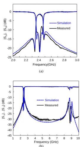
Fig.8(a) plots simulation and measured responses from 2 to 3 GHz and Fig.8(b) shows those from 1 to 10 GHz for the SIR filter with coupling structure B in Fig.6. The passband insertion loss is 1.7dB at the design frequency. The spurious response goes up at 8GHz, and before this frequency the attenuation level is about 30dB.
VI.CONCLUSION
A simple design for bandpass filters with a sharp transition is presented. The building blocks of the filters are quarter-wavelength uniform impedance resonators (UIRs) and stepped impedance resonators (SIRs) with a tapped open stub. Both direct coupling scheme and a three-line structure are used to realize the cascade of two coupled stages. Transmission zeros are created on both sides of the passband. The UIR design presents good |S11|
responses as well as good insertion loss in the passband, while the SIR design possesses a wide upper rejection band with a good attenuation level. All the presented filters show a sharp transition band.
REFERENCES
[1] J.-S. Hong and M. J. Lancaster, “Couplings of microstrip square open-loop resonators for cross-coupled planar microwave filters,” IEEE Trans. Microwave Theory & Tech., vol. 44, no. 11, pp. 2099–2109, Nov. 1996.
[2] J.-T. Kuo, M.-J. Maa and P.-H. Lu, “A microstrip elliptic function filter with compact miniaturized hairpin resonators,” IEEE Microwave and Guided Wave Letters, vol. 10, no. 3, pp. 94–95, Mar. 2000.
[3] C.-C. Yu and K. Chang, “Novel compact elliptic-function narrow-band bandpass filters using microstrip open-loop resonators with coupled and crossing lines,” IEEE Trans. Microwave Theory & Tech., vol. 46, no. 7, pp. 952–958, July 1998.
[4] K. Wada and I. Awai, “Heuristic models of half-wavelength resonator bandpass filter with attenuation poles," IEE Electronics Letters, vol. 35, no. 5, pp. 401–402, Mar. 1999.
[5] J.-T. Kuo and E. Shih, “Microstrip stepped impedance resonator bandpass filter with an extended optimal rejection bandwidth,” IEEE Trans. Microwave Theory Tech., vol. 51, no. 5, pp. 1554-1559, May 2003.
[6] S.-Y. Lee and C.-M. Tsai, “New cross-coupled filter design using improved hairpin resonators,” IEEE Trans. Microwave Theory and Tech., vol.48, no.12, pp. 2482–2490, Dec. 2000.
[7] J.-R Lee, J.-H. Cho and S.W. Yun, “New compact bandpass filter using microstrip λ/4 resonators with open stub inverter,” IEEE Microwave and Guided Wave Letters, vol. 10, no. 12, pp. 526–527, Dec. 2000.
[8] J.-T. Kuo and E. Shih, “Wideband bandpass filter design with three-line microstrip structures,” 2001 IEEE MTT-S Int. Microwave Symp. Dig., pp.1593-1596, May 2001.
[9] Zeland Software Inc., IE3D Simulator, Jan. 1997.
-25 2.0 Frequency(GHz) Measured Simulation -20 -15 -10 -5 0 2.2 2.4 2.6 2.8 3.0 |S |, |S | (d B ) 11 21 (a) -45 1 Frequency (GHz) Simulation Measured -40 -35 -30 -25 -20 -15 -10 -5 0 2 3 4 5 6 7 8 9 10 |S | , |S | (dB) 11 21 (b)
Fig. 8. Simulation and measured responses of filter structure B in Fig.6. (a) Detailed responses. (b) Responses in a broad band.