行政院國家科學委員會專題研究計畫 成果報告
WiMAX 天線與電波傳播特性之研究 研究成果報告(精簡版)
計 畫 類 別 : 個別型
計 畫 編 號 : NSC 97-2221-E-011-024-
執 行 期 間 : 97 年 08 月 01 日至 98 年 07 月 31 日 執 行 單 位 : 國立臺灣科技大學電機工程系
計 畫 主 持 人 : 楊成發
計畫參與人員: 碩士班研究生-兼任助理人員:蔡孟穎 碩士班研究生-兼任助理人員:翁崇訓 碩士班研究生-兼任助理人員:郭皇麟 碩士班研究生-兼任助理人員:林聖育 博士班研究生-兼任助理人員:劉獻文 博士班研究生-兼任助理人員:李原宏
報 告 附 件 : 出席國際會議研究心得報告及發表論文
處 理 方 式 : 本計畫涉及專利或其他智慧財產權,2 年後可公開查詢
中 華 民 國 98 年 10 月 29 日
WiMAX天線與電波傳播特性之研究
計畫編號:NSC 97–2221–E–011–024 執行期限:97 年 08 月 01 日至 98 年 07 月 31 日 計畫主持人:楊成發 教授 國立台灣科技大學 電機工程系 計畫參與人員:劉獻文、李原宏、翁崇訓、林聖育、郭皇麟、蔡孟穎
摘 要
本計畫乃針對WiMAX 通訊系統之天線與電波傳 播特性進行研究,其中結合射線柱追蹤法與時域有限 差分法,以發展 RT-FDTD 混合模擬程式,並應用此 程式來分析室內外WiMAX 頻段之電波傳播特性,且 進行相關之WiMAX 頻段無線電波場強分佈測量,以 與模擬結果比較驗證之。此外,亦將應用HFSS 電磁 數值模擬套裝軟體,來進行WiMAX 天線設計,並且 使用本校無反射實驗室來實測WiMAX 天線反射損失 與輻射場型,以驗證模擬結果。期能建立WiMAX 天 線 與 電波 傳播 特 性的 模擬 與 量測 技術 , 以應 用於 WiMAX 通訊系統之研發與建置。
關鍵詞:WiMAX、天線、電波傳播、射線追蹤法、
時域有限差分法
Abstract
In this project, antenna and wave propagation properties for WiMAX communication system have been studied. An RT-FDTD hybrid simulation program is developed by combining the ray-tube tracing program and finite difference time domain method. Thus, this RT-FDTD program can be applied to simulate wave propagation for indoor and outdoor environments for WiMAX wireless communications. Measurements of the field distributions for waves in WiMAX frequency bands are performed to compare with the simulated data.
Besides, HFSS electromagnetic numerical simulation software package has been employed to design WiMAX antennas. Then, measurements of the radiation patterns and return loss for the WiMAX antennas are performed by utilizing NTUST anechoic chamber to verify the simulated results. Those simulation and measurement techniques can be employed for designing WiMAX antennas and analyzing indoor/outdoor wave propagation properties, which may be applied in the R&D and deployment of the WiMAX communication system.
Key words: WiMAX, Antenna, Wave propagation, Ray tracing method, Finite difference time domain method
一、簡介
WiMAX (Worldwide Interoperability for Microwave Access) 通訊系統 [1]-[4]乃是泛指符合IEEE 802.16標 準所建置的無線都會區域網路(Wireless Metropolitan Area Network, WMAN),其為一種「遠距離無線寬頻 傳輸」的通訊技術。目前在美國和歐洲兩個地區已規 劃 出2.5GHz、 3.5GHz與 5.5GHz等 三 個 通 訊 頻 帶 給 WiMAX系統使用,而台灣方面則先採用2.5GHz與 3.5GHz兩個頻段作為商業用途,未來會視整體市場需 求再斟酌開放。WiMAX與Wi-Fi、xDSL、2G、3G等 系統最大的不同在於其具有高度的相容性與擴充性,
並且成功橫跨有線與無線之間的資料傳輸隔閡,可作 為未來4G之建置基礎。首先,WiMAX系統採用正交 多 工 分 頻 技 術 (Orthogonal Frequency Division Multiplexing, OFDM)、多重輸入多重輸出(Multi-Input Multi-Output, MIMO)技術、無失真資料壓縮技術、安 全加密技術並搭配使用分時多工或者分頻多工等方式 讓上傳跟下載通道在不同時間或不同頻帶進行資料傳 輸以達到雙向溝通之目的。其次,WiMAX系統的傳輸 距離長,最遠可達到50公里,亦即網路覆蓋範圍廣,
基地台細胞半徑在鄉村地區可達3公里以上,在都市區 域亦有1公里左右,下載速度最快可達75Mbps。因此,
WiMAX系統能夠帶來比現行3G系統更好的寬頻連線 品質,包括網路語音服務與各項即時性的應用,如互 動遊戲、視訊會議、音樂下載、大型檔案共享等,並 整合邁入至商業建置階段的4G行動寬頻技術。
在數位用戶迴路系統或纜線數據機等現行有線寬 頻裝置無法覆蓋的區域,WiMAX系統亦提供了全新的 解決方案,其具有在各種無線、有線通訊系統之間的 切換技術,業者無需增加成本來額外鋪設複雜的通訊 網路,就有機會開發數百萬的潛在寬頻用戶。在寬頻 基礎建設發展較完善的區域,WiMAX則能更具成本效 益地擴大既有的網路服務範圍,並且大幅改善網路速 度、傳輸效能與系統容量。目前WiMAX標準可提供兩 種方案作為選擇:固定式WiMAX(IEEE 802.16-2004) 以及行動式WiMAX(IEEE 802.16e),兩者都是依據 IEEE的標準規範,其中固定式WiMAX技術是專為地 形受限或寬頻網路無法覆蓋的區域所設計,得以讓這 些區域的家庭與商業用戶,都可以享受低成本、高頻 寬的連網環境,而行動式WiMAX除了提供固定式 1
WiMAX所有的一切效益外,同時也具備支援行動式裝 置的附加價值。在全球趨勢都邁向行動化應用發展的 今日,行動式WiMAX將扮演推動WiMAX市場快速植 根發展的重要角色。預計在WiMAX系統與xDSL/Cable Modem等現行有線寬頻接取技術相互合作之下,未來 WiMAX可以直接作為有線網路「最後一哩」的解決方 案,並可進一步擴展寬頻網路的服務範圍,提供消費 者更多樣化的選擇,以提升寬頻通訊網路的普及度。
本計畫即針對WiMAX通訊系統之天線和電磁波 場強分佈特性進行設計、模擬分析與測量,並且持續 發展與改良RT-FDTD電波混合模擬程式,以應用至 WiMAX系統於室內外與市區街道之電波傳播特性分 析,其中考慮了市區建築物之主體架構,來應用三維 廣射線柱追蹤程式進行廣泛區域之模擬,以使用於分 析涵蓋範圍廣闊的WiMAX系統之電波傳播特性,並且 針 對 室內 外之 小 區域 與特 定 物品 之電 波 特性 使用 RT-FDTD進行模擬分析。此外,為探討WiMAX系統 之天線特性,乃應用基於有限元素法之電磁數值模擬 軟體HFSS,來計算WiMAX天線之輻射場型與反射損 失,並於本校無反射實驗室進行天線場型與反射損失 之測量,並且應用自動化場強分佈量測系統,來測量 WiMAX頻段電波訊號於室內外之場強分佈特性,且與 模擬結果比較驗證之,冀能提升系統通訊的涵蓋品質。
2 二、具有雙帶拒特性之CPW饋入單極天線設計與分析
現階段WiMAX 系統所制訂開放的操作頻率範圍 有2.5GHz~2.69GHz、3.3GHz~3.8GHz、以及 5.25GHz~
5.85GHz 等三個頻段,不過一般現行的 WiMAX 天線 大都設計成寬頻[5]-[7]或是雙頻型態[8]-[11],然而在 實際應用於系統模組時,往往需要添加額外的帶通濾 波器才能夠滿足系統後端降頻及解調變等需求。因 此,本計畫係針對上述頻帶來設計出一款具備雙帶拒 特性之 CPW 饋入單極天線,並將其應用於後續電波 傳播之相關模擬與量測實驗。
本款天線為了符合WiMAX系統之多頻帶操作,乃 選擇單極天線型式作為設計基礎,天線的平面尺寸為 40x40mm2,而基板則採用厚度為 0.8mm的玻璃纖維 FR4,其介電常數為 4.4,損耗參數為 0.02,天線的幾 何結構與相關電氣特性係利用電磁模擬軟體HFSS來 加以分析。如圖 1(a)所示,本款天線的輻射體設計成 五角形之單極天線,其單邊長度為 16.5mm,而饋入 方式係利用50Ω CPW傳輸線來加以達成,其中信號線 寬度為5mm,而與接地面之間距則為 0.8mm,天線實 作如圖 1(b)所示。另外,為了讓本款天線於操作頻帶 範圍具有良好的阻抗匹配,亦將天線輻射體底部與 CPW接地面設計成具有θ2=38o之銳角分離結構;同 時,為了讓此款天線具備雙帶拒之特性,乃於天線輻 射體的中間位置嵌入兩條寬度為 0.2mm之細槽線 (slot),其長度約略為帶拒頻段中心頻率的二分之一導
波波長,藉以造成共振電流之擾動,進而產生兩個帶 拒頻段,上述所使用的導波波長計算方式如下所示。
eff o rejected
ε
λ = λ (1)
其中λrejected為導波波長,而λo則為自由空間之波長,
εeff則為有效介電常數,其等於(εr+1)/2。
(a) 天線結構
(b) 天線實作
圖1 具備雙帶拒特性之 CPW 饋入單極天線
圖2 為天線的模擬與實測之反射損失,可發現兩 者的數值相當接近,其中些微的誤差係來自於實作與 組裝的差異性,以及模擬參數未能考量額外的損耗所 導致。從 10dB 的反射損失實測值可以觀察出此款天 線具有三個操作頻帶,分別是 2.14GHz~2.85GHz、
3.29GHz~4.08GHz、以及 5.02GHz~6.09GHz,其符合 WiMAX 系統的頻段規範,故可滿足相關射頻信號之 接收需求。除此之外,我們所設計的帶拒頻段之中心 頻率位於3GHz 和 4.5GHz,同時這兩個帶拒頻段具有 相當陡峭之特性,故能夠有效阻隔非WiMAX 系統之 干擾,降低系統後端處理的複雜度,藉此提高整體系 統的接收效能。為進一步分析本款天線的帶拒效果,
我們亦模擬了不同的槽線長度所造成之影響,其相關
結果如圖3 所示。由圖中可以得知,這兩條槽線可以 個別單獨設計,其帶拒效能幾乎不會相互影響,因此 本款天線可配合不同的行動裝置來進行效能微調,並 相對減少帶通濾波器的使用數量。
1 2 3 4 5 6 7
20 15 10 5 0
Return Loss (dB)
Frequency (GHz)
simulated (HFSS) measured
1 2 3 4 5 6 7
20 15 10 5 0
圖2 模擬與實測之反射損失
3 (a) 上方槽線在不同的長度下所造成之帶拒效果
(b) 下方槽線在不同的長度下所造成之帶拒效果 圖3 天線帶拒效能分析
為檢視此款WiMAX 天線的共振原理,乃針對三 個操作頻帶的中心頻率來做共振電流之模擬分析,如 圖4 所示。由模擬結果可以看出,本款天線藉由 CPW 的饋入方式能夠獲得穩定的電流分佈,其意味會有較
好的輻射效能及遠場場型,同時透過此種設計可降低 板材對於天線共振模態的影響,藉以提高天線輻射效 能之穩定度。圖 5 為天線於 2.6GHz、3.5GHz、以及 5.5GHz 等中心頻率之實測遠場輻射場型,由圖中可以 觀察出在xz 平面為電場平面(E-plane)之輻射場型,而 yz 平面則為磁場平面(H-plane)之輻射場型。除此之 外,由於天線的三個工作頻帶皆屬於同一個共振模 態,因此其輻射場型亦相當接近,而其中yz 平面的場 型接近於全向性,故後續將可利用此平面來進行電波 傳播之模擬與量測。同時,為了滿足WiMAX 系統的 接收需求,天線的增益與效率亦必須相對穩定,以應 付不同距離之信號衰減,表1 即為本款天線於三個操 作頻帶之實測最大增益與輻射效率,其相關數據顯示 所設計之雙帶拒單極天線具備良好的增益與效率,在 三個工作頻帶至少有增益 1.85dBi 和效率 85%以上之 水準,完整的增益變化趨勢則繪於圖6 中。
(a) 2.6GHz之電流分佈
Return Loss (dB)
Frequency (GHz)
upper slot length 34mm 32mm (proposed) 30mm
1 2 3 4 5 6 7
25 20 15 10 5 0
Return Loss (dB)
Frequency (GHz)
lower slot length 24mm 22mm (proposed) 20mm
(b) 3.5GHz之電流分佈
(c) 5.5GHz之電流分佈 圖4 共振電流分析
4 (a) 2.6GHz遠場輻射場型
(b) 3.5GHz遠場輻射場型
(c) 5.5GHz遠場輻射場型 圖5 實測天線遠場輻射場型
表1 天線於操作頻帶之實測最大增益與輻射效率
頻率 (GHz)
最大增益 (dBi)
效率 (%)
頻率 (GHz)
最大增益 (dBi)
效率 (%)
2.5 1.99 87 5.25 3.26 87 2.6 2.07 88 5.35 3.35 88 2.69 2.22 90 5.45 3.44 88 3.3 1.85 85 5.55 3.66 90 3.4 2.03 87 5.65 3.87 89 3.5 2.08 89 5.75 4.06 87 3.6 2.24 90 5.85 4.24 86 3.7 2.34 89
3.8 2.43 88
黃色、綠色、粉紅色分為對應 至第一、二、三個工作頻帶
2 3 4 5 6 7
-10 -8 -6 -4 -2 0 2 4 6
5.25~5.85GHz 3.3~3.8GHz
Gain (dBi)
Frequency (GHz) 2.5~2.69GHz
圖6 實測天線增益變化
三、WiMAX電波傳播模擬與量測
為了分析WiMAX電波傳播的涵蓋範圍與衰減趨 勢,本計畫亦應用自行研發之RT-FDTD混合模擬程式 [12]-[17]來進行相關研究,而由於WiMAX系統具備大 範圍涵蓋的電波分佈特性,因此我們選擇台科大校園 內的一處空曠場所來做為模擬分析的地點,其相對位 置如圖7所示。在模擬的整體環境當中,上方為圖書 館,右側為行政大樓,左側及下方皆為空曠的場地,
發射端設定為本計畫所研製之雙帶拒單極天線,接收 端則設定為具有全向性場型之雙錐形寬頻天線,其中 接收端的路徑規劃係沿著A, B, C三條方向,每條方向 均有六個待測點,而相鄰兩點之間的水平和垂直距離 分別為3.2m與2m。至於發射端的位置則固定在B4及 C4兩點的正中間,並且架設成yz平面,藉以全向性地 輻射信號。此外,發射端與接收端均距離地面1.5m。
在模擬參數設定方面,圖書館及行政大樓的長度和高 度分別為30m×15m以及30m×16m,而牆壁厚度均設定 為0.3m,模擬頻率則挑選WiMAX系統三個規範頻段 之中心頻率來進行分析,分別是2.6GHz、3.5GHz與 5.5GHz,其中模擬空間的細胞間隔設定成2m為一點。
為檢驗RT-FDTD電波程式之模擬可靠度,本計畫 係利用微波向量網路分析儀(Agilent PNA-L, 10MHz~
20GHz)搭配所研發之WiMAX天線與標準雙錐形寬頻 天線(EMCO-3112, 1GHz~18GHz)來進行實際量測,並 且依照圖7的相對位置架設之。另外,量測中所使用的 微波纜線均校正至端點,藉以排除非傳播路徑之損失 (path loss)。同時,網路分析儀的傳送功率設定為 0dBm,以精確測量發射端與接收端兩者之間的傳輸損 耗(S21)。由圖8的結果可得知,模擬與實測之電波傳播 特性大致符合,其主要的誤差乃源自於材料的參數設 定不夠周全,以及實際量測的架設不夠精確所導致。
另一方面,由於B4及C4兩點較為接近發射端,因此可 獲得較強之場強分佈特性,至於A1, B1及C1等三點則 因為傳播距離較遠,所以其電波衰減情形較為明顯。
總而言之,透過模擬與實測兩者的比對分析,可發現 此款天線在不同位置皆具有良好的輻射效能,這與天 線本身的全向性輻射場型有關,而本計畫所研製具有 雙帶拒特性之單極天線將可實際應用在WiMAX系統 中。除此之外,透過天線良好的雙帶拒特性,能夠有 效地阻隔非WiMAX頻段信號之雜訊干擾,藉以降低系 統後端的處理複雜度並提高解析能力。
5 圖7 WiMAX電波模擬及實測之相對位置示意
A1 A2 A3 A4 A5 A6 B1 B2 B3 B4 B5 B6 C1 C2 C3 C4 C5 C6 -70
-60 -50 -40
S21 (dB)
Location
2.6GHz wave propagation simulated measured
(a) 2.6GHz模擬與實測之傳輸損耗
A1 A2 A3 A4 A5 A6 B1 B2 B3 B4 B5 B6 C1 C2 C3 C4 C5 C6 -70
-60 -50 -40
S21 (dB)
Location
3.5GHz wave propagation simulated measured
(b) 3.5GHz模擬與實測之傳輸損耗
A1 A2 A3 A4 A5 A6 B1 B2 B3 B4 B5 B6 C1 C2 C3 C4 C5 C6 -70
-60 -50 -40
S21 (dB)
Location
5.5GHz wave propagation simulated measured
(c)5.5GHz模擬與實測之傳輸損耗 圖8 WiMAX頻段電波傳播分佈特性之模擬及實測
五、結論
本計畫係針對WiMAX系統來設計出一款具有雙 帶拒特性之單極天線,此天線採取CPW的饋入方式來 達到較為穩定的輻射特性,並且將輻射體設計為五角 型式以滿足寬頻操作的需求,而透過嵌入雙槽線於天 線輻射體上,能夠產生陡峭的雙帶拒頻段,藉以阻隔 非WiMAX頻段之雜訊干擾。另一方面,為了研究 WiMAX 系 統 之 電 波 傳 播 特 性 , 本 計 畫 亦 利 用
6 RT-FDTD電波模擬程式來進行模擬分析,並與實際量 測結果比較之。由模擬及量測的數據顯示,本計畫所 研製的雙帶拒單極天線具備良好之傳播效能及帶拒特 性,預期將可應用於WiMAX接收機之天線設計,同時 本計畫所發展的電波模擬程式亦可應用在系統建置之 涵蓋分析。
參考文獻
[1] K. Lu, Y. Qian, and H.-H. Chen, “Wireless broadband access:
WiMAX and beyond-a secure and service-oriented network control framework for WiMAX networks,” IEEE Comm. Mag, vol. 45, no. 5, pp.124-130, May 2007.
[2] T.-H. Chan, C.-Y. Cheung, H. Mounir and M. Ma, “Overview of rate adaptation algorithms based on MIMO technology in WiMAX networks,” in Proc. IEEE Mobile WiMAX Symp., March 25-29 2007, pp. 98-103.
[3] D. Niyato and E. Hossain, “Radio resource management games in wireless networks: an approach to bandwidth allocation and admission control for polling service in IEEE 802.16,” IEEE.
Wireless Comm., vol. 14, no. 1, pp. 27-35, Feb. 2007.
[4] D. Niyato and E. Hossain, “Wireless broadband access: WiMAX and beyond - integration of WiMAX and WiFi: optimal pricing for bandwidth sharing,” IEEE Comm. Mag., vol. 45, no. 5, pp.
140-146, May 2007.
[5] X.-N. Low, W.-K. Toh, and Z.-N. Chen, “Broadband suspended plate antenna for WiFi/WiMAX applications,” in Proc. ICSP Int.
Conf., 10-13 Dec. 2007, pp. 1-5.
[6] K. G. Thomas, and M. Sreenivasan, “Compact triple band antenna for WLAN/WiMAX applications,” Electro. Lett., vol. 45, no. 16, pp. 811-813, July 2009.
[7] M. Al-Husseini, Y. Tawk, A. El-Hajj, and K. Y. Kabalan, “A low-cost microstrip antenna for 3G/WLAN/WiMAX and UWB applications,” in Proc. ACTEA. Int. Conf., 15-17 July 2009, pp.
68-70.
[8] K.-C. Yang, W.-S. Chen, and Y.-H. Yu, “Design of a WiMAX T-type monopole antenna with asymmetrical ground plane,” in Proc. IEEE AP-S Int. Symp., 5-11 July 2008, pp. 1-4.
[9] C.-S. Liu, C.-N. Chiu, and S.-M. Deng, “A Compact disc-slit monopole antenna for mobile devices,” IEEE Antennas Wire.
Propag. Lett., vol. 7, pp. 251-254, June 2008.
[10] Y. Tawk, K. Y. Kabalan, A. El-Hajj, S. Sadek, and M. Al- Husseini, “A modified bowtie antenna design for Wi-Fi and WiMAX applications,” in Proc. IWCMC Int. Conf., 6-8 Aug.
2008, pp. 729-732.
[11] T.-M. Hsueh, H.-T. Hsu, H.-T. Chou, and K.-L. Hung, “Dual band omni-directional planar antenna for WiMAX applications,”
in Proc. IEEE AP-S Int. Symp., 5-11 July 2008, pp. 1-4.
[12] T. S. Wang, and C. F. Yang, “Simulations and measurements of wave propagations in curved road tunnels for signals from GSM base stations,” IEEE Antennas Propag., vol. 54, no. 9, pp.
2577-2584, Sep. 2006.
[13] C.-P. Chang, and C.-F. Yang, “A moment method solution for the shielding properties of three-dimensional objects above a lossy half space,” IEEE Electro. Compat., vol. 47, no. 4, pp. 723-730, Nov. 2005.
[14] W.-Y. Chang, C.-F. Yang, W.-Y. Hwu, S.-K. Jeng, and H.-J. Li,
“Measurements and modeling of wave propagation over irregular
terrain for signals in the VHF band,” Journal of The Chinese Institute of Engineers, vol. 28, no. 3, pp. 401-412, May 2005.
[15] W.-Y. Chang, B.-C. Wu, C.-J. Ko, and C.-F. Yang, “A free space transmission approach for extracting the effective complex dielectric constants of the building structures,” International Journal of Electrical Engineering., vol. 12, no. 2, pp. 193-200, May 2005.
[16] C.-F. Yang, and B.-C. Wu, “A ray-tracing/PMM hybrid approach for determining wave propagation through periodic structures,”
IEEE Vehicular Tech., vol. 50, no. 3, pp.791-795, May 2001.
[17] C.-F. Yang, B.-C. Wu, and C.-J. Ko, “A ray tracing method for modeling indoor wave propagation and penetration,” IEEE Antennas Propag., vol.46, no.6, pp.907-919, June 1998.
行政院國家科學委員會補助國內專家學者出席國際學術會議報告
98 年 10 月 28 日
報告人姓名 楊成發 服務機構
及職稱
國立台灣科技大學 電機系 教授 時間
會議 地點
2009 年 03 月 23 日至 27 日
Beijing, China
本會核定
補助文號 NSC 97-2221-E-011-024
(1)會議名稱
(中文)
(英文) 2009 Progress In Electromagnetics Research Symposium 發表
論文 題目
(1)A Miniature Chip Antenna Design for a Passive UHF RFID Tag to be Built in a Portable Device
(2)A Metal Tag Antenna for Passive UHF RFID Applications 時間
會議 地點
2009 年 04 月 27 日至 28 日 Orlando, FL, U.S.A.
本會核定 補助文號
NSC 97-2221-E-011-024
(2)會議名稱
(中文)
(英文) 2009 IEEE International Conference on RFID 發表
論文 題目
參與研討與交流
一、 參加會議經過 (1.1) 2009 PIERS
本次的 2009 PIERS 國際研討會議選擇於中國北京 (Beijing, China) 舉辦,從 2009/03/23 至 2009/03/27 共計有五天的論文發表會,本人於論文發表會的第二天上 午發表了兩篇論文,其名稱分別為「A miniature chip antenna design for a passive UHF RFID tag to be built in a portable device」與「A metal tag antenna for passive UHF RFID applications」。第一篇論文設計出一款微型化的射頻辨識(RFID)標籤天 線,其有別於一般的阻抗匹配方式,係運用半準元件(quasi-lumped)來進行精確的 共軛匹配,以獲得最大功率傳輸,因此本款天線的效能將可大幅提昇,最遠的讀 取距離約可達 6m 左右。同時,由於此標籤天線具有較小的設計尺寸,並且兼具平 面式印刷的匹配電路,因此將可內建於智慧型手機或是筆記型電腦內來回傳 UHF 頻段之 RFID 訊號。另一方面,第二篇論文乃針對金屬物品來研發出一款被動式的 RFID 金屬標籤,其利用 CPW 饋入方式來達到與 IC 之間的阻抗匹配,並且具有較 寬的操作頻寬。同時,透過間隙耦合的設計模式來加強共振效果,藉以提高輻射 增益,其貼附於大片金屬表面時將可達到 4.5dBi,而最遠的讀取距離大約是 7.4m 左右,預計未來可以導入至車輛管理。
由於本研究團隊深耕在 RFID 和行動通訊等領域已有多年,對於天線、主被動 元件及電路、開發電波傳播軟體等方面已有相當豐碩之成果,所以本人除了參與 多場天線設計、微波電路與電波傳播的論文發表會之外,也另外參與幾場關於 RFID 議題之論文發表,藉以交流國際上之 RFID 發展現況。會議中並與一些專業 人士針對現行的 RFID 系統模組和晶片天線來做討論,其中亦包含本研究團隊所研 發之相關成果,反應相當熱烈。
(1.2) IEEE International Conference on RFID
本次的 2009 RFID 國際研討會議選擇於美國奧蘭多 (Orlando, FL, U.S.A.) 舉 辦,從 2009/04/27 至 2009/04/28 共計有兩天的論文發表會。此會議的相關論文及 成果發表皆屬於 RFID 領域的研究範疇,因此本人係針對 RFID 的天線/電路設計、
靜/動態量測技術、以及情境應用等方面來與各界專業人士進行交流及討論。除此 之外,本人於會議當中亦介紹本校 RFID 中心的最新發展情況,獲得與會人士的熱 烈迴響。
二、 與會心得 (2.1) 2009 PIERS
本年度2009 PIERS國際會議廣邀世界各國的專家學者共襄盛舉,會場中除了 展示多款新式的電磁模擬軟體及微波儀器,例如:FEKO、CST與ATK等,亦舉 辦了幾場短期課程,本會議係為電磁領域之研究學者及專業人士來共同討論最新 技術及相關議題,為電波界相當重要之大型國際會議,其會議發表成果包含下列 項目:數值方法、無線通訊、電磁測量、生物醫學應用和效應、電磁教學、天線 設計、陣列天線、行動通訊天線、材料電磁特性、電磁理論、週期性結構、電磁 逆散射、波導與傳輸線、微帶天線和電路、雷達影像、電波傳播、電磁散射及繞 射、雷達遙測、射頻辨識等多所交流。這些議題與本人的研究方向較為相關的 有:數值方法、無線通訊、電波傳播、週期性結構、電磁散射及繞射、天線設 計、RFID應用等方面。
參與此研討會著實有助於本人對目前及未來研究之規劃和實踐,並藉由與專 家學者之間的互動來瞭解其最新研究概況及長期目標,特別是在RFID應用與天 線微型化設計兩個領域方面。經由會議中的討論與分析,將有助於本人建立完整 的天線/電路設計、模擬軟體開發、以及量測技術等基礎,期能厚植國內無線通 訊的研發能量。
(2.2) IEEE International Conference on RFID
本次2009 RFID國際會議係集結世界各國的專業人士齊聚一堂,來共同討論 RFID的最新技術發展及相關應用,本次會議主題涵蓋:RFID政策、通訊協定、
系統結構分析、定位應用、天線設計、電波傳播、微波電路、感測網路、加密安 全性等,本人撥冗參與其中幾場重要的論文發表,並與相關人士進行交流討論。
三、 考察參觀活動
參觀會場中多家業者之產品介紹,其中如電磁模擬分析軟體、無反射實驗 室、微波量測儀器等,特別是與本校無線通訊與電磁相容技術研發中心已購置及 擬購置之相關軟硬體設備的資訊,並認識該公司之負責人或主管。
四、 建議
參與這些國際研討會除了可以瞭解各國在電波領域之發展,並能介紹本國一 些電磁研究現況,對於國內電波研究國際化之提昇有所助益。國科會能補助國內 專家學者參與國際會議,立意甚佳,可以增進吾人之國際視野,使國內研究能與 國外發展接軌,值得繼續支持之。
五、 攜回資料名稱及內容
攜回 2009 PIERS 及 2009 RFID 會議資料光碟共計兩片,內有本次會議所有的 發表文章
A Miniature Chip Antenna Design for a Passive UHF RFID Tag to be Built in a Portable Device
Yu-Shu Lin, Hsien-Wen Liu, Kuo-Hsien Wu, and Chang-Fa Yang
Department of Electrical Engineering, National Taiwan University of Science and Technology, Taipei, Taiwan
Abstract- In this paper, a miniature antenna for a passive UHF RFID tag is designed, which may be built in a portable device. Matching techniques for a Gen2 tag IC are employed to enhance the readable distance of the tag for long-range reading purposes, where quasi-lumped and lumped elements are used to match the chip antenna to the tag IC having complex input impedance. A commercial simulator, HFSSTM is used to analyze the performance of the antenna. Also, measurements in an anechoic chamber of the RFID education and research center at National Taiwan University of Science and Technology are performed to evaluate the readable range of the chip tag, which is more than 5m for a reader with an EIRP equal to 4W. The chip antenna operating in the 900MHz RFID band proposed here has dimensions of only 10×9.5×0.8mm3. Thus, this miniature tag may be flexibly built in a portable device to allow long-range reading.
1. INTRODUCTION
In recent years, Radio Frequency Identification (RFID) has been developed for many applications, such as supply chain managements, retail store applications, etc. For UHF passive RFID systems, the passive tags need to have good impedance matching to achieve efficient power transfer between the tag IC and antenna. Usually, tag antennas in ordinary half-wave dipole forms were designed [1]-[6]. In this paper, a miniature chip antenna having a size of only 10×9.5×0.8mm3 for the UHF RFID passive tag is presented, which can be easily built in a portable device. An impedance matching approach by using quasi-lumped components is also investigated and is compared with that by applying lumped elements. A commercial simulator, HFSSTM [7] has been employed to analyze the electrical characteristics of the tag antenna and quasi-lumped elements.
2. RESULTS
As shown in Fig. 1, a miniature chip tag operating in the RFID UHF band is proposed here, which has antenna dimensions of only 10×9.5×0.8mm3. To have a low cost design, this tag antenna is fabricated on an FR4 substrate with a relative permittivity εr = 4.4 and loss tangent δ = 0.02. Performance of the proposed tag antenna having an input impedance of 26+j3Ω is demonstrated in Fig. 2, where a 100×48mm2 test board is used here. The input impedance of the Monza Gen2 tag IC we have used is equivalent to that of an RC series circuit with R=33ohm and C=1.58pF. To achieve a conjugated match with this tag IC, as shown in Fig. 3(a), a lumped inductance of 18nH is serially connected between the proposed antenna and tag IC. Also, another matching circuit, composed of two compact quasi-lumped elements, is applied to obtain the conjugated match, as shown in Fig. 3(b).
This quasi-lumped circuit consists of a series inductance and a shunt inductance, where the equivalent values of the inductances are extracted to be 12.3nH and 12.5nH, respectively. Figure 4 shows the measured input impedances and reflections of the lumped and quasi-lumped designs for the proposed chip antenna. The quasi- lumped design has a wider bandwidth in the RFID UHF band.
The readable range of the tag was tested in an antenna measurement anechoic chamber, as shown in Fig. 5. A transmitting horn antenna with a gain Gt was fed by an RFID reader via a connecting cable with loss Lc. The proposed tag antenna, attached on a Styrofoam, was oriented to obtain the maximum power from the reader antenna. Since RF charging of the passive tag by the reader is the critical part for a success reading, the maximum readable range for a given EIRP can be determined by the following formula [6]:
c tL G P d EIRP r
min
max (1)
where d is the distance between the tag and the transmitting antenna, Pmin is the minimum power of the reader to be able to read the tag, Gt = 5.7dBi and Lc = -1.5dB at 922MHz for the chamber system. In those measurements, d was fixed at 3.6m, and the measured Pmin for lumped and quasi-lumped designs were individually obtained to be 29dBm and 28dBm. Therefore, if the EIRP of the reader is set to 4W, the maximum readable ranges with the lumped and quasi-lumped designs will be 5m and 5.5m, respectively. Besides, read-range experiments were also performed in a corridor to compare with those from chamber measurements, as listed in Table 1. Due to multi- path contributions, the distances measured in the corridor were longer in this test case.
3. CONCLUSIONS
In this paper, we have proposed and analyzed a miniature chip antenna with lumped and quasi-lumped matching circuits for passive UHF RFID tag applications. The performance of the proposed tag antenna was examined through the readable range measurements in an anechoic chamber. The compact chip tag with either quasi-lumped or lumped matching circuits can have a readable range more than 5m with a 4W EIRP reader.
REFERENCES
1. K. V. Seshagiri, P. V. Nikitin Rao and S. F. Lam, “Antenna design for UHF RFID tags: a review and a practical application,” IEEE Trans. Antennas Propag., vol. 53, no. 12, pp. 3870-3876, Dec. 2005.
2. Q. Xianming and Y. Ning, “A folded dipole antenna for RFID,” in Proc. IEEE AP-S Int. Symp. Dig., June 2004, pp. 97-100.
3. J. Ahn, H. Jang, H. Moon, J.-W.Lee and B. Lee “Inductively Coupled Compact RFID Tag Antenna at 910 MHz with Near-Isotropic Radar Cross-Section (RCS) Patterns,” IEEE Ante. and Wireless Propag. Lett., vol.
6, pp.518-520, June 2007.
4. H.-W. Son and C.-S. Pyo, “Design of RFID tag antennas using an inductively coupled feed,” Electronics Lett., vol. 41, no. 18, pp. 994-996, Sept. 2005.
5. Y.-W. Liu, S.-Y. Chen and P. Hsu, “Short-ended coplanar strip antenna for UHF RFID tags,” in Proc. IEEE AP-S Int. Symp. Dig., June 2007, pp. 1773-1776.
6. K. Kurokawa, “Power waves and the scattering matrix,” IEEE Trans. Microw. Theory Tech., vol. 13, no. 3, pp. 194-202, Mar. 1965.
7. HFSS, User’s guide 9.2, Ansoft Corp., USA.
Fig. 1 Geometry of the proposed miniature chip tag antenna.
(a) (b)
Fig. 2 The performance of the proposed passive tag antenna. (a) Return loss (b) Simulated far-field radiation pattern at 922MHz
(a) (b)
Fig. 3 Configurations of the lumped and quasi-lumped matching circuits. (a) Lumped circuit with L1=8mm, L2=11.75mm, L3=1.95mm, L4=2.25mm, L5=7.2mm and L6=4mm (b) Quasi-lumped circuit with L7=4mm and L8=4mm
(a) (b)
Fig. 4 Measured input impedances and return losses of the proposed tag antenna with the lumped and quasi- lumped matching circuits. (a) Input impedance (b) Return loss
(a) (b)
Fig. 5 The readable range measurements in an anechoic chamber. (a) Measurement setup (b) Chamber environment
Table 1 Experimental results of readable range measurements.
Readable range Matching circuit
Maximum range in the corridor
Maximum range in the anechoic chamber
Lumped elements 5.8m 5m
Quasi-lumped elements 6m 5.5m
A Metal Tag Antenna for Passive UHF RFID Applications
Hsien-Wen Liu, Yu-Shu Lin, Kuo-Hsien Wu, and Chang-Fa Yang
Department of Electrical Engineering, National Taiwan University of Science and Technology, Taipei, Taiwan
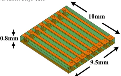
Abstract- In this paper, a passive tag antenna operating in RFID UHF band is presented, which may be mounted on a metallic object. This metal tag antenna design is composed of a slot radiator, a capacitive coupling structure and a coplanar waveguide (CPW) feed to provide a good power transfer to the tag IC. No additional matching network is required to achieve a conjugated matching between the tag IC and the proposed tag antenna. A commercial simulator, HFSS is used to analyze the proposed antenna performance. This tag antenna for the 900MHz RFID band has dimensions of only 93(L)×20(W)×3.4(H)mm3, and therefore can be easily attached on metal surfaces, such as license plates for vehicle managements. Also, the antenna with low cost, easy fabrication and high efficiency are achieved by using a 0.4mm FR4 PCB attached on a 3mm PP substrate. For the metal tag mounted on the license plate, the maximum readable range measured in an anechoic chamber is more than 7m for a reader with an EIRP equal to 4W.
1. INTRODUCTION
In recent years, Radio Frequency Identification (RFID) has rapidly attracted high attention in many commercial applications, such as supply chain managements, retail store applications and tracking goods. For UHF passive RFID systems, the passive tags must have a good impedance matching to achieve efficient power transfer between the tag IC and antenna. Many literatures [1]-[5] have investigated the tag antennas for various RFID applications. In this paper, we propose a passive UHF tag antenna having dimensions of only 93(L)×20(W)×3.4(H)mm3, which may be mounted on a metal object, such as being attached on a license plate for vehicle managements. A commercial simulator, HFSSTM [6] has been applied to analyze the electrical characteristics of the metal tag antenna. Also, the readable range of the metal tag has been measured in an anechoic chamber of the RFID education and research center at National Taiwan University of Science and Technology.
2. RESULTS
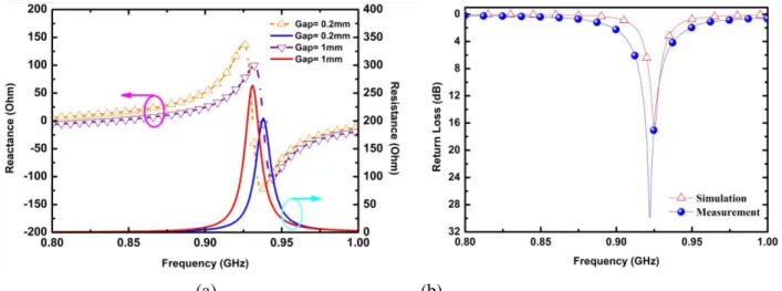
As shown in Fig. 1, the proposed metal tag antenna consists of a slot radiator, a capacitive coupling structure and a coplanar waveguide (CPW) feed, which has dimensions of only 93(L)×20(W)×3.4(H)mm3. This tag antenna is fabricated on a 0.4mm FR4 PCB and attached on a 3mm poly-propylene (PP) substrate, where the FR4 substrate has a relative permittivity εr = 4.4 and loss tangent tanδ = 0.02, and the PP substrate has εr = 2.3 and tanδ = 0.006. Also, Impinj Monza Gen2 tag IC with an input impedance of 33-j112 ohm is used here. To achieve a conjugated match with the tag IC, the gap width of the capacitive coupling structure was varied to tune the input impedances of the tag antenna, as shown in Fig. 2(a). Note that the return loss of the proposed antenna can be obtained by the following equation
S L
S L
Z Z
Z Z
20log * log
20
(1)
where ZL is the impedance of tag IC and ZS is the input impedance of tag antenna.
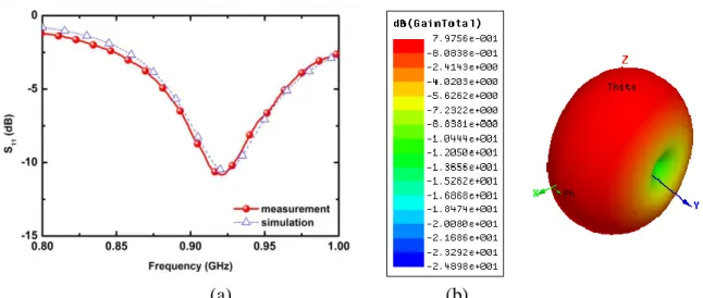
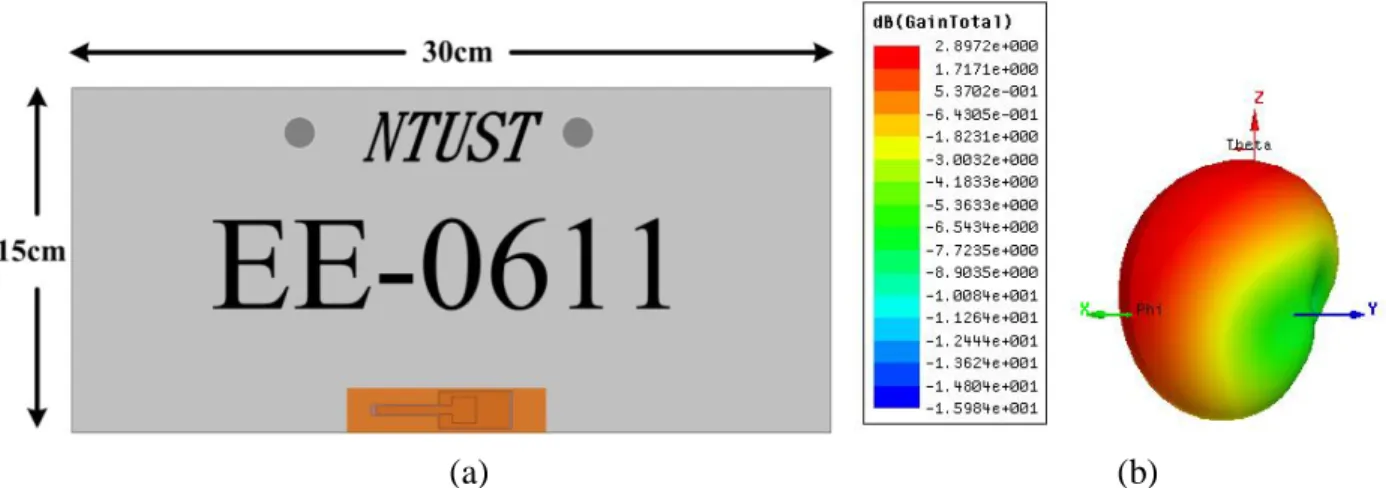
Both simulations and measurements for the return loss of the antenna terminated with the tag IC are plotted in Fig. 2(b), which show a good matching in the RFID UHF band. Also, fair agreements between simulated and measured results are observed, although the measurements indicate a wider bandwidth. This difference may be due to measurement errors caused by a probing cable connecting the antenna input terminal. For examining the antenna performance, the proposed metal tag is attached on a metal plate with dimensions of 30×15cm2, as shown in Fig. 3(a). The simulated 3D far-field pattern of the metal tag on the plate at 922MHz is plotted in Fig. 3(b), where a main beam in the upper forward direction is obtained as desired.
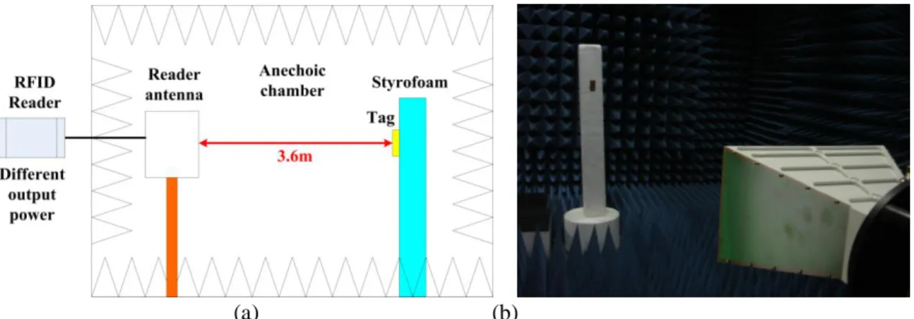
The readable range of the proposed tag was tested by using the far-field antenna measurement anechoic chamber, as shown in Fig. 4. A transmitting horn antenna with a gain Gt was fed by an RFID reader via a connecting cable with loss Lc. The proposed tag antenna, attached on a Styrofoam with or without the metal plate, was oriented to obtain the maximum power from the reader antenna at a fixed distance d. Since RF charging of the passive tag by the reader is the critical part for a success reading, the maximum readable range in free space can be determined by the following Friis transmission formula [5]:
c tL G P d EIRP r
min
max
(2)
where d is the distance between the tag and the transmitting antenna, Pmin is the minimum power of the reader to be able to read the tag, Gt = 5.7dBi and Lc = -1.5dB at 922MHz in our chamber. Since the measured Pmin’s with and without the metal plate are 25.5dBm and 29.5dBm, the maximum readable ranges are 7.3m and 4.6m, respectively. Also, the readable range was tested in a corridor. Comparisons of the results obtained in the chamber and corridor are given at Table 1, where the distance measured in the corridor for the metal tag alone is longer than that obtained in the chamber. However, for the metal tag attached on the plate, the readable distances are about the same. The longer-distance reading is caused by multi-path contributions in the corridor, which are more significant for the metal tag without the plate due to its omni-directional pattern.
3. CONCLUSIONS
A compact metal tag antenna for passive UHF RFID applications has been proposed and analyzed in this paper. This metal tag may be easily mounted on a metal object. Performance of the tag was examined with simulations and measurements. The maximum readable distance of the metal tag on a metal plate measured in an anechoic chamber is more than 7m for a reader with an EIRP equal to 4W.
REFERENCES
1. K. Rao, S.-F. Lam and P. V. Nikitin, “Wideband metal mount UHF RFID tag,” in 2008 IEEE AP-S Int. Symp.
Dig., July 2008, pp. 1-4.
2. D.-U. Sim, D.-H. Kim, J.-I. Choi and H.-D. Choi, “Design of novel dipole-type tag antennas using electromagnetic bandgap (EBG) surface for passive RFID applications,” in 2007 IEEE AP-S Int. Symp. Dig., June 2007, pp. 1333-1336.
3. C. Cho1, H. Choo1 and I. Park, “Design of Novel RFID Tag Antennas for Metallic Objects,” in 2006 IEEE AP-S Int. Symp. Dig., July 2006, pp. 3245-3248.
4. H.-W. Son and C.-S. Pyo, “Design of RFID tag antennas using an inductively coupled feed,” Electronics Lett., vol. 41, no. 18, pp. 994-996, Sept. 2005.
5. K. V. Seshagiri, P. V. Nikitin Rao and S. F. Lam, “Antenna design for UHF RFID tags: a review and a practical application,” IEEE Trans. Antennas Propag., vol. 53, no. 12, pp. 3870-3876, Dec. 2005.
6. HFSS, User’s guide 9.2, Ansoft Corp., USA.
(a)
(b)
(c)
Fig. 1 The proposed passive metal tag antenna. (a) Geometry (b) Antenna structure (c) Photograph
(a) (b)
Fig. 2 Input impedance and return loss of the metal tag antenna for different gap widths in the capacitive coupling structure. (a) Input impedance (b) Return loss
(a) (b)
Fig. 3 The metal tag mounted on a license plate. (a) Geometry (b) Simulated far-field radiation pattern at 922MHz
(a) (b)
Fig. 4 The readable range measurements in an anechoic chamber. (a) Measurement setup (b) Chamber environment
Table 1 Readable range measurements of the metal tag with a 4W EIRP reader.
Site
Tag Anechoic chamber Corridor
Alone 4.6m 6.5m
On a metal plate 7.3m 7.4m