行政院國家科學委員會專題研究計畫 成果報告
具清潔側壁與底部功能微小型水下機器人之研發 研究成果報告(精簡版)
計 畫 類 別 : 個別型
計 畫 編 號 : NSC 99-2221-E-011-026-
執 行 期 間 : 99 年 08 月 01 日至 100 年 09 月 30 日 執 行 單 位 : 國立臺灣科技大學機械工程系
計 畫 主 持 人 : 鄭逸琳
計畫參與人員: 碩士班研究生-兼任助理人員:李榮哲 碩士班研究生-兼任助理人員:孫凱閔
報 告 附 件 : 出席國際會議研究心得報告及發表論文
處 理 方 式 : 本計畫涉及專利或其他智慧財產權,2 年後可公開查詢
中 華 民 國 100 年 10 月 12 日
行政院國家科學委員會專題研究計畫結案報告 具清潔側壁與底部功能微小型水下機器人之研發
Development of Small-scale Underwater Robot with Side-wall and Bottom Cleaning Functions 計畫編號:NSC99-2221-E-011-026
執行期限:99 年 8 月 1 日至 100 年 9 月 30 日 主持人:鄭逸琳 國立台灣科技大學機械工程系
Email: [email protected] 研究人員:李榮哲、孫凱閔
中文摘要
現今水下玻璃帷幕或中大型魚缸,主要 以人工方式進行清潔,並無適當之微小型水 下清潔機器人滿足清潔需求。本研究使用創 新的三角架構概念,設計並製作具清潔功能 之微小型水下清潔機器人原型,本年度以側 壁清潔為主。透過此三角形架構與系統整 合,搭配簡化的運動操控模式與路徑規畫,
達到預定清潔之功能。三角外型機器人有三 個曲線外殼,每個面上裝置一馬達螺旋槳 組,而機器人中央也裝置一馬達螺旋槳組負 責 Z 軸方向的移動,清潔裝置則裝於三角形 的三個角落處。透過快速成型與快速模具技 術,製作機器人原型所需的零件,並將各模 組組裝後進行水下測試,機器人可以成功地 逐一清潔魚缸中的牆面,並移動到下一個垂 直位置進行下一層的清潔。
關鍵字:水下清潔、機器人、系統整合、快 速成型、快速模具
英文摘要
Nowadays the underwater cleaning of the exhibition glass walls in aquariums or large fish tanks is mainly done by manual work. There is no suitable small-scale underwater cleaning robot for this purpose. In this research, innovative triangular-frame concept was adopted to design and fabricate a prototype of underwater cleaning robot. In particular, this
year’s works focused on side-wall cleaning.
Through this simple triangular structure and system integration, together with simple moving modes and path planning, the cleaning function can be achieved. The triangular robot had three curved shells. Each shell had a DC motor attached to it, and one motor was placed in the center for Z-axis movement. The cleaning module was placed at three corners. Parts of the robot prototype were manufactured by Rapid Prototyping (RP) and Rapid Tooling (RT) techniques. The underwater tests were conducted after assembly of all the modules.
The robot could successfully clean the walls of a fish tank one by one and move to the next vertical position for next-layer cleaning.
Keywords: Underwater cleaning, Robot, System Integration, Rapid Prototyping, Rapid Tooling
1.
前言海洋的浩瀚無垠一直是人類探 索 的 動 力,世界各國無不積極參與相關的開發動 作,使得機械船舶設備亦是持續不斷地改 良,水下器械的發展近年來更是拜科技突飛 猛進所賜,開發出各種先進的大型水下研究 設備,如深水探測儀器、水下機械手臂、水 下遙控載具、水下清潔機器人等。目前的水 下清潔工作,大多以大型的泳池清潔機器人
為主軸,而水下展場的玻璃帷幕或是中大型 魚缸,則多以人工方式進行清潔,並無適當 之微小型水下清潔機器人滿足清潔需求。因 此本研究整合現有技術資源,並以創意、創 新的理念建構出簡易控制的微小型水下清潔 機器人。
2.
研究目的目前大型泳池的水下清掃機器人,主要清 潔游泳池底,但所佔體積龐大且必須有粗大 的電線,更加要考量到游泳池的潮濕環境造 成的漏電危險;而在一般水族缸的玻璃壁面 清潔上都以人工方式使用磁力刷和刮刀清 潔,用在小型水族缸確實是較於方便,但對 於中型以上甚至更大型的區域玻璃缸就顯得 十分的不方便。因此,本研究目的在於研發 微小型水下清潔機器人使用於中型以上的四 角型之水族缸玻璃壁面、水族館玻璃壁面,
並以簡易控制系統滿足其清潔需求。本年度 計畫以清潔側壁為目標,清潔底部之功能將 於後續年度進行。一般水下機器人大都設計 為對稱的機構,單一動作通常需要至少兩個 的動力驅動,並需要搭配昂貴複雜的電子零 件與軟體做為控制系統。本研究提出以三角 外型設計,清潔側壁時,只需單馬達之驅動 即能完成推進與清潔動作,同時便於角落順 勢轉向。只要搭配簡單、較低成本之電子零 件即做到簡易控制達到清潔之效果,降低成 本及耗能,具節能減碳之概念。
3.
文獻探討近年來各類型水下機器人的發展可說是爭 奇鬥艷,各自發展出特色,以下為詳細介紹。
1998 年 Doty【1】提出可利用小型潛水艇 當成人類的眼睛或耳朵, 取得海底資料進而 傳送,並朝著便宜易操控且具智慧型的小型 潛水艇,在這裡研究方向是朝海底偵測,在 潛水艇上搭載如聲音感測器或影像穿輸裝 置,就可達到此目的。外型如圖 1 所示。
在 2001 年 Hobson【2】提出利用小型水 下載具對海底世界作 3D 的影像探測,在載 具前端有搭載許多感測器如溫度、深度等
等,透過這些感測器不僅有導航功能,更可 以取得海底資訊。外型如圖 2。
圖 1 Doty 小型潛水艇 圖 2 Hobson 小型水下載 具
2002 年日本的 GUO【3】提出仿魚類生物 的小型載具,提出利用 ICPF(Ionic Conducting PolymerFilm) actuator 當作推進系統,同時說 明未來小型載具可用於醫學治療和工業管路 探測,希望藉由小型的潛水艇達到探測目 的。外型如圖 3。
2005 年美國佛羅里達州大學師生【4】研 製 SubjuGator 自 組 水 下 載 具 參 加 2005 AUVSI/ ONR 8th 國際水下載具競賽,為運作 在水下超過 32 呎深度的設計。SubjuGator 系 統包含感測器、馬達控制器和其它必需的週 邊設備。外形如圖 4。
圖 3 仿魚類生物小型載具 圖 4 SubjuGator
哈 爾 濱 工 程 大 學 海 洋 智 能 機 械 研 究 所
【5】,研製水下雨刷清潔機器人,該水下清 刷機器人主要由交流伺服電機驅動系統、磁 吸附系統、控製系統和清刷作業裝置等組 成。該機器人的主要技術指標,適應水下 10 公尺內的淺船體表面的工作環境、負重能力 不小於 300N、移動速度為 0 至 8 m/min 可 調、控制模式為有線遙控。如圖 5 所示。
水面上的清潔機器人“Kraken"【6】,主要 由五個組件所架構:控制、光學探測器、推進
力、放置系統。而機器人的控制系統使用的 是 Eyebot 的 控 制 卡 是 由 微 處 理 機 Motorola68332 所組成,藉由 C 編譯程序能 夠創立機器人的程序和控制的例行程序,光 學的探測系統是給予機器人更高級的自主性 的重要一環。機器人外型如圖 6 所示。
圖 5 水下雨刷機器人 圖 6 Kraken
在 2009 年澳門大學的電機工程學系【7】
建構了如下圖 7 所示的清潔功能的手臂,動 力學和運動學分析水下機器人專為清潔水 池。設計了水下機器人以滿足需要的清潔工 作。清潔工作可分為兩個主要部分:底部清 洗和側壁清洗。
2010 年英國曼徹斯特大學為了開發出適用 能夠於高度雜亂環境的核能儲存池做研究工 作 的 微 小 水 下 自 動 機 器 人 群 ( 單 體 尺 寸 200mm 以內) 【8】,而針對了各種可能的推 進方式進行搜索與研究,其中包含了水平方 向的推進或垂直方向的推進,以及人工式推 進或仿生式推進。最終在考慮成本、研究時 間與效能後,得出的結論是馬達螺槳組是最 好的選擇,設計機器人的外型如圖 8 所示。
圖 7 清潔機器人設計圖 圖 8 微小型水下自動機 器人
而本實驗室亦於水下機器人領域發展多 年,其研究成果如下:
2005 年 沈 毓 珊 - 微 小 水 下 載 具 之 製 作
【9】,著重在探討微小水下載具製作的可行
性及載具的系統整合,包括馬達挑選、螺槳 的設計、製作和推力測試、腔體設計與製作、
載體組裝。外型如圖 9。
2006 年賴佳宏-微小潛艇之設計與製作
【10】,研究以雙螺槳為動力源,發展可操控 方向之微小潛水艇,著重在探討微小潛水艇 製作的可行性及整體的系統整合,包括馬達 挑選、螺槳設計與製作、推力測試、潛艇本 體設計與製作,以及最後的水下測試。外型 如圖 10。
圖 9 微小水下載具 圖 10 微小潛艇
2007 年張瑞東-具觀測能力的無線遙控微 小水下載具之研發【11】,究研發以無線遙控 方式控制具有觀測能力之微小水下載具。微 小水下載具裝置無線微型攝影機與四個推進 器—兩組作為推進,另外兩組作為深度控 制。藉由觀測的影像,傳達給操作者以無線 遙控器控制微小水下載具的運動狀態與觀測 目標物。外型如圖 11。
2008 年莊文鴻-微小型水下機器人之研發
【12】,本研究為微小型水下清潔機器人之初 期研究,具有推進器、吸附裝置、清潔單元、
電路及控制模組。所設計之吸附裝置,運用 螺槳的推力來吸附於玻璃表面,除可穩固地 吸附於玻璃表面特定位置,讓清潔單元進行 清潔工作外,並可將此裝置作為微小型水下 清潔機器人在水中運動的推進器,具有兩全 其美的效用。外型如圖 12。
圖 11 無線遙控微小水下 載具
圖 12 微小型水下機器人
4.
研究方法本研究的程序如圖 13 所示,首先定義出 對機器人的訴求,評估後進行機器人的初步 外型設計,接著規劃並測試機構外型的移動 運作,接下來考慮移動和轉向因素、清潔機 構和供電的模式,經過實驗之後決定其模式 與和測試電路系統後,最後做路徑的規劃和 判斷,進行水下的性能測試。
圖 13 研究程序圖
(1) 創新清潔架構
一般水下機器人大都採對稱的設計,在 作動時必須使用雙數的馬達以維持平衡,而 本研究跳脫出如此概念,以三角外型的外型 搭配單驅動馬達即可完成動作,主要是利用 斜向的兩方向力來同時完成前進和貼附牆面 兩動作。角落的轉向機制以機器人前進的速 度動力配合另外一方的馬達驅動產生吸力使 水下機器人在角落時能轉向至下一面牆之清 潔預備位置。
清潔材料以具有良好清潔效果、不傷清 潔面、多次利用性、簡易裁剪性之科技泡棉 當作清潔之材料,黏附於三角形水下機器人 的角落圓柱上,利用水下機器人依靠壁面行 進時,產生摩擦力達到清潔之功用。而角落
轉向感測元件,放棄一般需較多空間與電流 的壓力感測器,改採容易取得的應變計,貼 附於 PI(Polyimide)材料上,整合於機器人的角 落端,當機器人行經牆角時,PI 材料受到彎 曲使應變計亦產生變形,電壓值的差異經放 大後,將可用於馬達驅動之自動化控制。
(2) 馬達控制與驅動模組
機器人驅動馬達選擇國內廣營電子有限 公司生產之 EM300H 型號直流馬達,擁有高 轉速與高扭力的表現,且重量僅有 46 公克。
而馬達之控制是以達靈頓電路搭配兩個繼電 器的方法來達到穩定且簡單的正反轉電路系 統,因本研究含有四顆馬達,共需要八顆繼 電器來控制馬達正反轉。
控制方面採用單晶片來製作控制器,控制 晶片為 Microchip 公司所推出,型號為
PIC18F2520。應變計彎曲後產生電壓值變 化,利用 OP 放大器增加其變化差異量供單晶 片讀取,並下達指令於馬達的控制電路,控 制流程如圖 14 所示。
圖 14 水下清潔機器人控制流程圖
(3) 外型與螺旋槳系統設計
外型的設計是考量馬達尺寸、電路 線 徑、厚度等細部條件後開始建構,為了讓水 流阻力降低因此將機器人的外型以弧線形狀 呈現,厚度為 3mm,並在三面弧壁正中心配
置一馬達的框架,內部設計防水填油空間,
並於三個角落上建立放置清潔材料的圓柱。
上下蓋一樣是三角弧外型的 3mm 薄板,並在 中心建構一個中空圓柱用以放置 Z 軸的直流 馬達。建構完成的機器人如圖 15 所示,整體 尺寸為 270mm*250mm* 120mm。
圖 15 水下清潔機器人 3D 架構設計
機器人由於三個馬達放至於外型側壁的 弧面上,每個馬達的驅動機構皆有一定長 度,所以螺旋槳的設計必須考量三角弧外型 的範圍以防清潔時碰觸牆面,最後決定選用 遙控船艇模型的螺旋槳,外徑為 35mm ,而 Z 軸馬達之外徑為 38mm ,如圖 16 所示。
圖 16 船艇模型用螺旋槳
本研究使用小型馬達驅動螺旋槳,雖然 在空氣中其轉速及扭力表現不錯,但由於在 水下使用時,需要高扭力之輸出來提高效率 並降低馬達負載,因此使用行星齒輪減速機 將有效提供以上之功用。行星齒輪組減速機 (Planetary gear reducer)利用齒輪間的速度轉 換將馬達之迴轉數降低,並得到較大轉矩。
在減速比方面,考慮不影響原本馬達之框架 尺寸,使用環齒輪為 27mm 之 5:1 減速機,
而在行星齒輪與行星架之間將套入培林軸承 增加其運轉時之流暢度並減少磨耗,圖 17 為 此行星齒輪減速機之爆炸圖。平面馬達使用 的行星齒輪減速機直徑為 33mm,而 Z 軸升 降 之 馬 達 使 用 行 星 齒 輪 減 速 機 直 徑 為 27.4mm。
圖 17 行星齒輪減速機爆炸圖
(4) 機器人原型製作
本研究以 OBJET 公司的 EDEN 330 快速 成型(RP)系統,協助製作機器人原型所需零 件,其所使用的建構材料為 OBJET 公司所研 發的專用光硬化樹脂,Mold 建構材料型號為 FullCure720 、 Support 支 撐 材 料 型 號 為 FullCure705。由於該光硬化樹脂容易吸收水 氣以致變形,又 RP 材料價格昂貴,因此與水 接觸的零件、重複的零件,多以搭配快速模 具(Rapid Tooling)方式,將快速成型系統所製 作出來的工件翻成矽膠模,然後翻製出機器 人所需之零件,以降低成本並符合外型、強 度之需求。
(5) 水下測試
水下清潔機器人組裝完成後,接著執行 水下測試,主要可分為兩類測試:
(a)
性能測試性能測試主要測試機器人的推力、吸附 力 與 下 潛 力 , 其 測 試 環 境 為 長 62cm 、 寬 30cm、盛水高度為 35cm 之水槽,並於其上架 設一電子吊秤,如圖 18 所示。測試方式以細 線固定於機器人上,放入水中利用電子吊秤 進行量測工作。
圖 18 性能測試之水槽
(b)
功能測試功能測試主要測試機器人在水中以感測 器感應之後藉由應用程式的內容進行反應動 作及其清潔狀態,其測試平台為長 90cm×寬 60cm×高 45cm 之水槽。
5.結果與討論
(1) 清潔單元與角落轉向感測元件
科技泡棉的清潔材料,黏貼於三角型水 下機器人角落處的圓柱外緣,如圖 19 所示。
貼在 PI 材料上的應變計以 PDMS 封裝,貼附 於角落(如圖 20),做為角落轉向感測元件,並 配合差動 OP 放大器電路,將應變計的電壓 變化放大 100 倍,使其變化量能達到單晶片 可讀取偵測之 scale。測試結果,彎曲後電壓 變化量約為 0.003V,經放大後增至 0.3V,更 容易控制其驅動時機。
圖 19 角落處清潔單元 圖 20 應變計之裝置
(2) 清潔路徑
根據水下清潔機器人的創新三角外型設 計,以及對其的功能訴求,我們設定機器人 的清潔路徑如圖 21 所示。
圖 21 清潔路徑作動示意圖
實際運作說明如下:
a.將機器人放置 P1(初始點)。
b. 開啟朝向後側的馬達,使其產生推力來
讓機器人產生前進的推力與貼附於壁面上的 吸附力。
c. 當機器人前端的應變計碰觸到下一個壁 面時,利用朝向後側的馬達產生推力,以及 朝向前側的馬達產生吸力,讓機器人作逆時 針旋轉的動作直到貼附於下一壁面。
d. 重複步驟 b~c,直到回到 P1 為止。此時 開啟 Z 軸馬達將機器人移動到第二層,並繼 續上述的清潔動作。
(3) 水下機器人原型 (a)
電路與控制本研究以應變計感測器經彎曲後產生電 壓值變化,利用其 OP 差動放大器增加其變化 差異量供單晶片讀取,並下達指令於達靈頓 IC 驅動繼電器電路進而達成馬達控制,並可 經由切換開關轉變作動模式為以撰寫完成之 應用程式內容執行動作,以及可選擇手動模 式。整體電路模組之電路圖,分別為差動放 大電路、燒錄電路與模式開關電路、達靈頓 與繼電器電路。測試完成之後將電子零件分 別焊接於 48mm×73mm 之小型電路板上方便 置入水下清潔機器人之腔體中,並且將其外 接線路由上方之集線孔穿出,控制電路系統 如圖 22 所示,置入水下清潔機器人腔體中如 圖 23 所示。。
圖 22 控制電路系統圖
圖 23 電路置於水下清潔機器人
主要控制電路放置於水下清潔機器人之 腔體中,而控制的系統中以控制盒做為切 換,如圖 24 所示,可切換為感應模式/程式模 式及手動模式/自動模式。
圖 24 控制盒介面
(b)
螺槳裝置由於馬達的軸徑與螺 旋槳的軸徑不 相 同,因此特地設計出符合本研究使用之連結 軸,在馬達軸與連結軸之間設置了兩個垂直 的螺絲,可在馬達軸放入後鎖緊防止打滑,
而在連結軸和螺旋槳之間則藉由凸起塊與螺 旋槳的凹槽部分緊配合達到防止打滑的動 作,其組裝如圖 25 所示。
圖 25 連結軸與螺旋槳(左)及螺槳裝置完成
(c)
組裝當所有的原型零件製作完成後,進行水 下清潔機器人整體的裝配工作。馬達及其線 路一律從上蓋的孔洞接出,並注意防水,而 Z 軸中空馬達框架則藉由雙圓柱連接處的孔洞 將線路牽出亦從上面的孔洞外接。馬達裝置 前,在馬達框架前方預留的防水油槽填入黃 油後,裝上馬達並將連結軸鎖定後,套入導 流套件再裝上螺旋槳。應變計感應器透過下 蓋上的小孔洞進入水下清潔機器人腔體,透 過上面孔洞接出,而各個接縫處則以方便除 去的黏著材料進行黏著,如熱熔膠、矽膠等。
接著裝配三角上各個清潔材料圓柱支架,並 套入清潔材料,整體裝配完成後,進行水下 清潔機器人之秤重,不包含線路的重量為 752 克。完成之機器人如圖 26。
圖 26 水下清潔機器人組裝完成
(4) 水下測試結果
(a)
性能測試採用電子吊秤進行前進推力、吸附力與 下潛力之水下測試,測試結果前進推力為 74 g,吸附力為 168g,下潛力為 30 g。
(b)
路徑測試水下清潔機器人可利用平面的三顆馬達 做平面移動,Z 軸馬達做升降移動,利用三個 圓柱上之清潔材料於移動中摩擦水槽牆面進 而達成清潔動作。按照預設的路徑規劃,將 水下清潔機器人置於水槽一角落,其可貼附 於牆面並作直線前進,當到達角落時應變計 作動,使機器人完轉向,之後繼續以直線前 進摩擦清潔,其測試過程如圖 27 所示。
(a) (b)
(c) (d)
(e) (f)
(g) (h)
(i) (j) 圖 27 機器人清潔路徑測試過程
(c)
清潔測試水下清潔機器人以大面積之清潔材料進
行摩擦清潔,並能順利清潔角落,大幅度降 低清潔死角,圖 28 為清潔過程之截圖,清潔 髒汙面積為 5×20mm^2,由於清潔材料屬於消 耗品容易產生凹凸不平地方以致其些許面積 尚未擦拭,而清潔來回六趟的時候已將大部 分髒汙擦除。
(a) (b)
(c) (d) 圖 28 水下清潔流程圖
(5) 討論
測試結果顯示,水下機器人可以達到清 潔測避之目的。在運作初期,機器人在清潔 過程中能以相同高度來作前進,但經過一段 時間,可看出在高度的維持上會產生不穩 定,甚至會產生傾斜的情況,探究其原因可 能為: (I) 用來與控制器連接的控制線路所造 成的干擾。(II) 清潔材料含水量提高,造成機 器人密度的改變。由於水下清潔機器人以低 數量四顆馬達進行緊湊之空間設計, Z 軸中 空馬達框架之對流空間可望再改良。此外,
以 PDMS 方式封裝之應變計可使其於水中正 常感測應變,即能夠以低成本達到與市面上 昂貴的防水型應變計相同的效果。但由於這 是我們第一次將含有 PI 材料的應變計用於水 下感測,致使產生感測上的不穩定性,未來 將可研究以其他貼覆材料或者黏貼方式,來 達到更穩定之效果。
本研究整體來說,由表一可看出,與本 實驗室先前的水下清潔機器人【12】做比較,
可發現在性能、功能上皆有明顯的進步。
表一、新舊水下清潔機器人比較
文獻【11】 本研究
體積 186*186*123mm 270*250*120mm
重量 1090g 752g
下潛力 101g(四顆馬達) 30g(一顆馬達) 吸附力 436g(四顆馬達) 168g(一顆馬達)
前進推力 22g 74g
清潔範圍 區塊清潔 大範圍清潔
移動摩擦 底部接觸摩擦大 點接觸摩擦小
6. 結論
本研究開發水下清潔機器人,本年度先 以側壁清潔為主,以三角外形設計,規劃其 簡易的大清潔面積作動模式,當水下機器人 進行到牆面角落時,以應變計作為水下感測 的單元,驅動馬達的連動可以順勢產生轉向 的動作,並以此方式做循環式的清潔。水平 面層的循環式清潔後,利用 Z 軸的馬達驅動 至另一層進行下一個水平面層的清潔。整體 電路系統以簡易化、低成本之概念達到水下 清潔機器人之控制系統。當機器人前進時只 需單顆馬達作動,並利用馬達驅動螺旋槳時 所產生之扭矩與牆面互相抵衡,藉此來降低 耗費的電力、整體的重量和所占空間,不僅 簡化控制的模式,更能符合節能減碳之議題。
7. 參考文獻
[1] Keith L. Doty, A. Antonio Arroyo, Carl Crane Scott Jantz, David Novick, Robert Pitzer, Aamir Qaiyumi,“An Autonomous Micro-Submarine Swarm and Miniature Submarine Delivery System Concept,”Proc. of Florida Conference on Recent Advances in Robotics, FIT, March 26-27, 1998.
[2] Brett Hobson, Bryan Schulz, Jason Janet, Mathieu
Kemp, Ryan Moody , Chuck Pell, Heather
Pinnix ,“Develoment of a Micro Autonomous
Underwater Vehicle For Complex 3-D Sensing ,”
IEEE Conference and Exhibition , Volume: 4 , 5-8 Nov. 2001.
[3] Shuxuang Guo, Toshio Fukuda, and Kinji Asaka,
“Fish-like Underwater Microrobot with 3 DOF,”
Proc. of 2002 IEEE International Conf. on Robotics and Automation, Volume: 1 , 11-15 May 2002..
[4] William Dubel, James Greco, Aaron Chinault, Carlo Francis, Adam Barnett, Kevin Claycomb, Alan Melling, Eric M. Schwartz, A. Antonio Arroyo,
“SubjuGator 2005,” Machine Intelligence Laboratory, University of Florida Gainesville.
( http://subjugator.org/)
[5] 哈 爾 濱 工 程 大 學 國 家 大 學 科 技 園 / 成 果 推 介 , (http://www.heusp.com/rc-show.asp?id=143)
[6] A. Rincon-Suarez, M. Rubin-Falfan, E.
Sanchez-Sanchez, G. Trinidad-Garcia, H. Juarez, E.
Rosendo, T. Diaz, G. Garcia Salgado, "Design and Construction of an Autonomous Cleaner Robot, for an aquatic environment," CERMA, pp.482-487, Electronics, Robotics and Automotive Mechanics Conference (CERMA 2007), Sept. 2007.
[7] Yangmin Li and Ka Meng Lo, “Dynamics and Kinematics of Novel Underwater Vehicle-Manipulator for Cleaning Water Pool,”
IEEE International Conference on Mechatronics and Automation, August 9-12, 2009.
[8] Simon A. Watson, Peter N. Green, “Propulsion Systems for Micro-Autonomous Underwater Vehicles (µAUVs),” IEEE Conference on Robotics, Automation and Mechatronics, 2010.
[9] 沈毓珊,“微小水下載具之製作,” 臺灣科技大學 機械工程研究所碩士論文, 2005 年。
[10] 賴佳宏,“微小潛艇之設計與製作,” 臺灣科技大 學機械工程研究所碩士論文, 2006 年。
[11] 張瑞東,“具觀測能力的無線遙控微小水下載具 之研發,” 臺灣科技大學機械工程研究所碩士論文, 2007 年。
[12] 莊文鴻,”微小型水下清潔機器人之研發,”台灣
科技大學機械工程研究所碩士論文,2008 年。
國科會補助專題研究計畫項下出席國際學術會議心得報告
日期:100 年 10 月 12 日
一、參加會議經過
本次的 ICMST 2011 研討會在新加坡舉行,其實是有數個由
IACSIT(International Association of Computer Science and Information Technology,
www.IACSIT.org) 所辦的研討會一起,ICMST 2011 所佔的 sessions 最多,共有 8 個
sessions;共有來自超過 12 個國家的人員參加,發表的文章約有 94 篇。三天的研討 會,第一天為報到日,第二天早上為 keynote speeches,下午只有一個大 session 是
ICMST 的;第三天則是以 ICMST 的 sessions 為主。
二、與會心得
由於大會的 proceedings 是以 Advanced Materials Research Journal 紙本發行,
且是事後寄送,又無 abstract list 可供參考,無法事先挑選有興趣的 paper 去聽,只能 計畫編號 NSC 99-2221-E-011-026-
計畫名稱 具清潔側壁與底部功能微小型水下機器人之研發 出國人員
姓名 鄭逸琳 服務機構
及職稱 台灣科技大學機械工程系 副教授 會議時間 100 年 9 月 16 日至
100 年 9 月 18 日 會議地點 新加坡
會議名稱 2011 International Conference on Manufacturing Science and Technology - ICMST 2011
發表論文 題目
Design and Rapid Manufacturing Structural Components of a Mini-scale Underwater Vehicle
照著 session 的順序,為美中不足之處。與會者有許多印度人,讓人見識到印度精英 份子太過 aggressive 的嘴臉,令人無法茍同。本人原本為該 session 的 session chair,
但前一個 session 遲到的 session chair,逕自當起我們的 session chair,非常 rude 且蔑 視女性,也令工作人員及其他報告者傻眼;亦有其他 session 的 chair (也是印度人)為 了讓自己能得到 excellent paper 與獎金,篡改已給的評分,進而讓自己的分數最高。
不過是一個研討會與學術交流的地方,何必如此,日後也許應與印度來的人保持距 離!其他國家的人(如馬來西亞),相對就友善許多,本人亦邀請他們參加明年度在台 灣舉辦的 ICAM 2012 國際研討會。
T0041 Investigations on fume formation rate in shielded metal arc welding process using different electrodes
M. Shahul Hameed, K.R. Balasubramanian, S. P. Sivapirakasam and R. Nagalakshmi National Institute of Technology, Tiruchirappalli – 620015, Tamil Nadu, INDIA T0042 A study on the effect of V-ring position on the die roll height in fine blanking for special
automobile seat recliner gear
Jong-Deok Kim, Heung-Kyu Kim, Young-Moo Heo, Sung-Ho Chang Korea Institute of Industrial Technology
T0044 Development of inorganic gas barrier material in solar cell devices for planarization properties and sublimate defect reduction
Satoshi Takei
Toyama Prefectural University
T0045 FEM of Residual stress of EDMed Surfaces
Chandan Kumar Biswas and Mohan Kumar Pradhan NATIONAL INSTITUTE OF TECHNOLOGY, ROURKELA, INDIA
T0047 Calculation of Fundamental Mechanical Properties of Single Walled Carbon Nanotube Using Non-local Elasticity
Kuldeep Kumar Saxena, Vivek Srivastva, Kamal Sharma GLNA Institute of Technology, Mathura (U.P.), India-281406 T0086 Kinematic Modeling and Analysis of a Multifingered Robotic Hand
P.K.Parida, B.B.Biswal and M. R. Khan
National Institute of Technology, Rourkela, Orissa, India
T0105 High Speed Impact Characteristics of Plastic Material Based on Finite Element Simulation Waluyo Adi Siswanto
Universiti Tun Huseein Onn Malaysia (UTHM)
T0097 Study of Effect of Geometry parameters on Piezoelectric Cantilever by Modal And Harmonic Analysis
Abhay Khalatkar,Vijay Kumar Gupta , Rakesh kumar Haldkar
PDPM Indian Institute of Information Technology, Design & Manufacturing ,Jabalpur T0106 A Study on Extraction Method of Non Geometry Information in Engineering Drawing Title Block
Mohd Fahmi Mohamad Amran, Riza Sulaiman, Suziyanti Marjudi and Saliyah Kahar Universiti Kebangsaan Malaysia
S0892 Canal reach deformation monitoring technology Based on Terrestrial LIDAR scanning technology Liang Jun Han Xianquan,Hu Bo and Tan Yong
Yangtze River Scientific Research Inst, Wuhan, China
S0895 Traffic Engineering for Provisioning Hose Model VPNs with Delay Requirements Yu-Liang Liu
Dept. of Computer Science and Information Engineering, Aletheia University
10:30 - 10:40 Coffee break
Morning, September 18, 2011 (Sunday) SESSION – 12 (ICMST 2011)
Venue: Grand Ballroom Time: 10:40 – 12:10
T0049 T-rough Ideal and T-rough Fuzzy Ideal in a Semigroup S.B.Hosseini, N. Jafarzadeh, A.Gholami Islamic Azad University, Sari, Iran
T0050 Design and Rapid Manufacturing Structural Components of a Mini-scale Underwater Vehicle Yih-Lin Cheng and Rui-Dong Chang
National Taiwan University of Science and Technology
T0053 Interfacial Microstructure and Strength of Friction Welding of Steel Tube to Aluminium Tube Plate using an External Tool
S. Muthukumaran, C. Vijaya Kumar, S. Senthil Kumaran, A. Pradeep National Institute of Technology, Tiruchirappalli, India.
T0054
The Effect of Protective Coatings on the Oxidation Behavior of 6061Al/SiC Composite at High Temperatures
N. K. Udayashankar, Rajasekaran.S and Jagannath Nayak National Institute of Technology kaenataka
T0056
Parametric optimization of PMEDM process with chromium powder suspended dielectric for minimum surface roughness and maximum MRR
Dr Rajiv Kumar Garg and Kuldeep Ojha NIT JALANDHAR INDIA
T0059
Neural network based modeling in wire electric discharge machining of SiCp/6061 Aluminum metal matrix composite
Pragya Shandilya , P.K. Jain and N.K. Jain Indian Institute of Technology, Roorkee
T0063
Deformation behavior in pipe production process for a new high strength microalloyed Steel Sadegh Moeinifar
Islamic Azad University, Shoushtar Branch
T0064
Multi Objective Optimization of Noise and Vibration in Passenger Car Cabin by Using Goal Programming Approach
Ahmad Kadri Junoh, Zulkifli Mohd Nopiah, Wan Zuki Azman Wan Muhamad and Mohd Jailani Mohd Nor
Universiti Malaysia Perlis (UniMAP)
S0916
Construct an INLP Mathematical Model to solve the Two-sided Assembly Line Balancing problem of Type-3
Chun-Hsiung Lan and Ma Su Yee
No.101,Sec.1, Fenliao Rd, Linkou District, New Taipei City, Taiwan(R.O.C), Hsin Wu Institute of Technology.
S0857
The simulation of six phase PMSM taking iron loss into account Dong Xing, Xiaoning Zhang,Yongling FU and Haitao QI Beihang university, 37 Xueyuan Road, Haidian District, Beijing, China
12:10 - 13:30 lunch break
Afternoon, September 18, 2011 (Sunday) SESSION – 13 (ICCSM 2011)
Venue: Emerald Room Time: 13:30 – 15:30 S1007
DASM: A NEW FRAMEWORK FOR MODELING AND EVALUATION OF DISTRIBUTED ALGORITHMS Vahid Khalilpour, Moharram Challenger , Ali Farzan and Vahid Heydarinezhad
Islamic Azad University Shabestar Branch, Tebriz , East Azerbaijan , Iran
Design and Rapid Manufacturing Structural Components of a Mini-scale Underwater Vehicle
Yih-Lin Cheng1, a and Rui-Dong Chang1
1Department of Mechanical Engineering, National Taiwan University of Science and Technology,
#43, Section 4, Keelung Road, Taipei, Taiwan, R.O.C.
Keywords: underwater vehicle, layered manufacturing, Shape Deposition Manufacturing (SDM).
Abstract. Underwater vehicles have been developed mainly for underwater exploration and rescue.
Many large- and middle-size vehicles are available but few are in smaller scale. As the size goes into mini-scale which is less than 20 cm, it is challenging to allocate required components within limited space, while providing designed functions at the same time. The aims of this research are to design and rapid manufacture structural components for a remote-controlled underwater vehicle in the mini-scale region. The vehicle would integrate vision capability to provide functions of underwater ecological observation and tracking. In order to design the structural components for this mini-scale vehicle, commercial CFD software was adopted to simulate flows. An improved external shape was obtained and detailed designs of the structural components were implemented. A rapid prototyping technique, Shape Deposition Manufacturing (SDM) process, was utilized to rapidly manufacture these components. The finished components were assembled with control modules and propulsion systems as an underwater vehicle and the preliminary underwater test was conducted successfully.
Introduction
Underwater vehicles were developed mainly for underwater exploration and rescue. Many large-size and middle-size autonomous underwater vehicles had been built, such as University of Southampton’s AutoSub[1], and MIT’s Odyssey series[2]. They are usually in meters long and weigh tens to hundreds of kilograms. Small-scale underwater vehicles have the length dimension less than a meter [3,4,5]. Their sizes were usually greater than 50 cm in order to include sufficient sensors and provide basic control functions. As the size goes less than 20cm into mini-scale, it becomes a great challenge to allocate required components within limited space, while to provide designed functions at the same time. Also, non-standard components are not easily available commercially. In this study, a mini-scale remote-controlled maneuverable underwater vehicle with vision capability was planned to develop for underwater ecological observation and tracking. Specifically, this paper focuses on the design and rapid manufacturing of this underwater vehicle’s structural components. Commercial CFD software was adopted to help structure design improvement, and one of the rapid prototyping techniques, Shape Deposition Manufacturing (SDM) process, was used to rapidly manufacture these structural components for a preliminary underwater test.
Underwater Vehicle Structure Design
The structure of the mini-scale underwater vehicle contains a main hull structure and four frame structures of the propulsion unit. The design of the main hull structure needs to keep the vehicle small in volume while providing enough inside space for remote control, vision, and propulsion system control modules. The frame structure of the propulsion unit is used to hold motor and rotor together and contains a shroud to protect rotor and conduct flows. The initial external structure design is shown in Fig. 1. Flow simulation was conducted to understand the performance of this design.
A commercial CFD software, FLUENT, was used to simulate the fluid flows through this underwater vehicle, and helped to identify areas for improvement in the external shape design. Since the structure of the underwater vehicle is symmetric along the central plane, the simulation only took
half of the structure to reduce calculation time. The flow field was divided into three regions—main, front, and back. The length of the main region, L, equals to the length of the underwater vehicle (142 mm), while the width and height (W) is 74 mm. The length of front region was set to be 2.5L and the back one was 5L. Moreover, the height of front and back region are 4W, whereas the width to be 2W.
The overall calculation field is about 1200 mm x 150 mm x 300 mm. An unstructure grid, triangle element, was chosen for meshing main channel and denser grids were taken at the ends of shrouds (Fig. 2). The front and back channels used triangle elements as well with denser grids around the boundary areas to the vehicle. The total node number was 165091. For the boundary type setting, the front-end surface was defined as VELOCITY INLET and the back-end was PRESSURE OUTLET.
The rest of the surfaces, except the symmetry one at the central line of the vehicle, were set to be WALL. The setting of the boundary condition of the inflow velocity was 1 m/s. The number of iterations was set to be 150 with the convergence of 0.001.
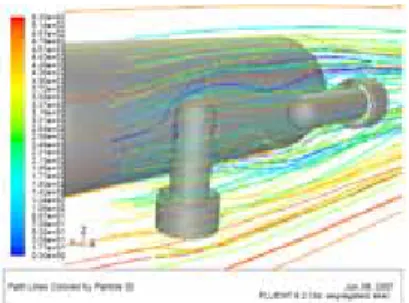
Fig. 1 Initial external structure design Fig. 2 Meshing results of the main channel The simulation result of streamlines is shown in Fig. 3. The front-end of the vehicle and the front propulsion units, which encounter the flow, undergo high pressure. The stagnation point at the front tip of the vehicle generates separation, and wakes happen at the back-end of the vehicle. If we moved the flow inlet plane backward to be close to the front propulsion units, the streamline distribution demonstrates more details between the two propulsion units (Fig. 4). Wakes and disordered streamlines indicate higher drags. According to these simulation results, the shape of vehicle’s front-end and back-end, and the frame structures of propulsion units were modified to reduce drags.
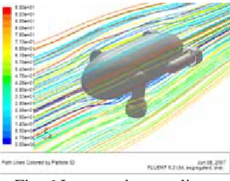
The improved design is shown in Fig. 5. The updated simulated streamlines are shown in Fig. 6 and 7.
Separation and wakes were diminished and the streamline distribution was improved. After the external shape of the underwater vehicle is determined, we can start to implement detailed designs of the structure components.
Fig. 3 Simulation result of streamlines Fig. 4 Streamline between two propulsion units
Fig. 5 Modified external structure design
Fig. 6 Improved streamlines Fig. 7 Improved streamline between two propulsion units The detailed design of the main hull structure is divided into three components— lower cover, upper cover, and battery case (Fig. 8). The lower cover contains major allocation of control circuits, mini camera, space for counterweights, connections to propulsion units, and slot for battery case. The upper cover is designed to increase internal space with shell structure and assembly features. The battery case provides space for rechargeable batteries and can be screwed into the bottom of the lower cover. The frame structures of front and back propulsion units are similar except the length. The frame is designed to have space to hold a motor with rotor, shroud to protect rotor and conduct flow, and assembly features to connect to the main hull. For manufacturing’s convenience, the frame structure is split into two portions as shown in Fig. 9.
(a) Lower cover (b) Upper cover (c) Battery case (a) Upper portion (b) Lower portion Fig. 8 Structural components of main hull structure Fig. 9 Frame structure of propulsion units
Rapid Manufacturing of Structural Components
A layered manufacturing technique, Shape Deposition Manufacturing (SDM) process [6] with a sequence of additive and subtractive steps, was used to rapid manufacture structural components for the mini-scale underwater vehicle. In the SDM process, the 3D part is sliced into several layers possibly with various thicknesses. In each layer, part material or support material are deposited in approximate volume and machined to net shapes. After the part is complete, the support material is removed thermally and chemically. In this application, room-temperature cured polyurethane (FENCAST FC 52 Polyol/ 52 Isocyanate by Huntsman Advanced Materials GmbH, Switzerland) was used as the part material. File-a-wax and Protowax (by Kindt-Collins Company, USA) are two candidates for support material. Protowax has lower melting point and shrinkage, comparing to File-a-wax. However, the machinability of protowax is not as good as File-a-wax. Therefore, in the base layer where the support material requires intensive machining, File-a-wax was used. Protowax was used in other layers to reduce shrinkage and thermal deformation when deep features exist. If shrink and thermal deformation effects are not obvious, the combined wax with 25% File-a-wax and 75% Protowax, the same as in the literature [7], was adopted. At the end when the part is complete, the support material is removed by BIOACT 280 (Petroferm Inc., USA) at 65 oC.
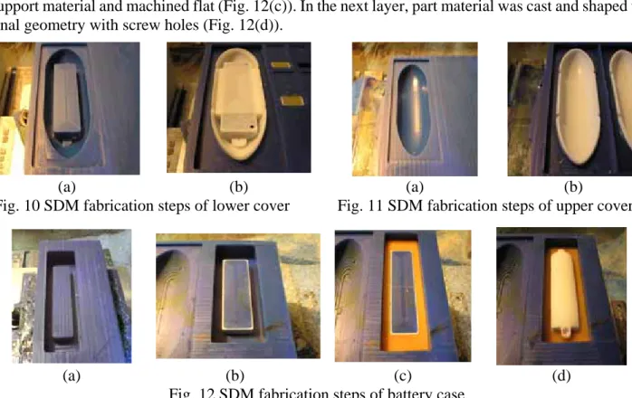
For manufacturing the lower cover of the main hull structure, two SDM layers were adopted. In the first layer, the File-a-wax base was machined to have bottom geometry of the part (Fig. 10(a)).
The second layer involved part material casting and machining to the inner features (Fig. 10(b)).
Similar process steps were applied to the upper cover, as shown in Fig. 11. The battery case is designed to assemble with the lower cover by two screws, and there exist undercut features at the
screw holes. Separated layers were required at the undercut surface in SDM process planning. At first, the File-a-wax base was machined to create the inner shape of the case (Fig. 12(a)). After deposition of the part material, the case geometry was machined up to the undercut surface (Fig. 12(b)). Since no deep features are involved in this component, combined wax was cast to fill up the areas which need support material and machined flat (Fig. 12(c)). In the next layer, part material was cast and shaped to final geometry with screw holes (Fig. 12(d)).
(a) (b) (a) (b)
Fig. 10 SDM fabrication steps of lower cover Fig. 11 SDM fabrication steps of upper cover
(a) (b) (c) (d) Fig. 12 SDM fabrication steps of battery case
The frame structures of the propulsion units contain upper and lower portions. The geometry of the front and back units are the same, except the length. Therefore, we can fabricate the eight components, upper and lower portions of front and back units, at the same time. At first, the File-a-wax base was machined to attain outside contour of the shroud for both upper and lower portions (Fig. 13(a)). After deposition of part material, the inner shape of the shroud was machined (Fig. 13(b)). Next, Protowax was cast as support material, and shaped the different features for upper and lower portions (Fig. 13(c) and (d)). In the following layer, the deposited part material was machined to get features for motor placement and indexing posts/holes (Fig. 13(e)). Fig. 13(f) shows eight completed components of propulsion units.
(a) (b) (c)
(d) (e) (f) Fig. 13 SDM fabrication steps of frame structure for propulsion units
Final Assembly and Tests
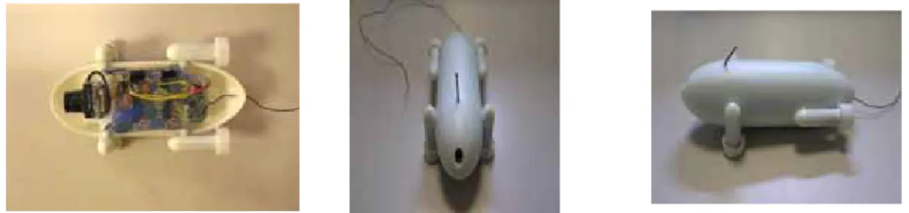
The finished structural components after support material removal were ready to assemble with control modules and propulsion systems to form a mini-scale underwater vehicle. The result is shown in Fig. 14. The overall dimension of this vehicle is 14.2 x 7.4 x 5.0 cm, with a total weight of 233 grams including all modules and battery. The preliminary underwater test was done in a fish tank to test its thrust at full power. The underwater vehicle was hung at the end of a spring. The power of the back propulsion units was on and increased to its maximum. A video camera recorded the elongation of the spring. We can calculate the thrust through Hooke’s law and found the maximal thrust generated by the two back propulsion units was 4.738gf.
Fig. 14 Assembled remote-controlled mini-scale underwater vehicle with vision capability
Conclusions
In this research, the structural components of the mini-scale underwater vehicle, including the main hull and four frames of propulsion units, were designed. The external shape was modified after CFD simulation in order to have better streamlines distribution and less wakes and separation. Detailed designs were employed to provide enough inside space for various modules, batteries, and propulsion systems. The SDM process was applied to rapidly manufacture the designed 3D complex structural components. As a result, the finished structural components were assembled with control modules and propulsion systems for a preliminary thrust test. This research has successfully designed and rapidly manufactured prototypes for a mini-scale underwater vehicle, and the approaches are applicable to other similar applications.
References
[1] P.G Collar and S.D. McPhail: IEE Electronics & Communication Engineering Journal, Vol. 7, No. 3 (1995), p. 105-114.
[2] Information on AUV Lab Vehicles, AUV Lab at MIT Sea Grant (http://auvlab.mit.edu/vehicles/) [3] B. Hobson, B. Schulz, J. Janet, M. Kemp, R. Moody , C. Pell, H. Pinnix: Develoment of a Micro Autonomous Underwater Vehicle For Complex 3-D Sensing, IEEE Conference and Exhibition, Vol.
4 (2001).
[4] S.B. Williams and I. Mahon: Design of an unmanned underwater vehicle for reef surveying, Proceedings of IFAC 3rd IFAC Symposium on Mechatronic Systems (2004).
[5] P. Walters, D. Hughes, T.P. Feeney, S. Nayak, N. Fischer, G. Dash, E.M. Schwartz, A.A. Arroyo:
SubjuGator 2010, Florida Conference on Recent Advances in Robotics, FCRAR 2010 (2010).
[6] R. Merz, F.B. Prinz, K. Ramaswami, M. Terk, L. Weiss: Shape Deposition Manufacturing, Proceedings of the Solid Freeform Fabrication Symposium (1994), p.1-8.
[7] Y.-L. Cheng and J.-H. Lai: Journal of Materials Processing Technology, Vol. 201 (2008), p.640-644.
國科會補助計畫衍生研發成果推廣資料表
日期:2011/10/12
國科會補助計畫
計畫名稱: 具清潔側壁與底部功能微小型水下機器人之研發 計畫主持人: 鄭逸琳
計畫編號: 99-2221-E-011-026- 學門領域: 機器人學及應用
無研發成果推廣資料
99 年度專題研究計畫研究成果彙整表
計畫主持人:鄭逸琳 計畫編號:99-2221-E-011-026- 計畫名稱:具清潔側壁與底部功能微小型水下機器人之研發
量化
成果項目 實際已達成
數(被接受 或已發表)
預期總達成 數(含實際已
達成數)
本計畫實 際貢獻百
分比
單位
備 註 ( 質 化 說 明:如 數 個 計 畫 共 同 成 果、成 果 列 為 該 期 刊 之 封 面 故 事 ...
等)
期刊論文 0 0 100%
研究報告/技術報告 0 0 100%
研討會論文 0 0 100%
論文著作 篇
專書 0 0 100%
申請中件數 0 0 100%
專利 已獲得件數 0 0 100% 件
件數 0 0 100% 件
技術移轉
權利金 0 0 100% 千元
碩士生 2 2 100%
博士生 0 0 100%
博士後研究員 0 0 100%
國內
參與計畫人力
(本國籍)
專任助理 0 0 100%
人次
期刊論文 0 0 100%
研究報告/技術報告 0 0 100%
研討會論文 0 0 100%
論文著作 篇
專書 0 0 100% 章/本
申請中件數 0 0 100%
專利 已獲得件數 0 0 100% 件
件數 0 0 100% 件
技術移轉
權利金 0 0 100% 千元
碩士生 0 0 100%
博士生 0 0 100%
博士後研究員 0 0 100%
國外
參與計畫人力
(外國籍)
專任助理 0 0 100%
人次
其他成果 (無法以量化表達之成 果如辦理學術活動、獲 得獎項、重要國際合 作、研究成果國際影響 力及其他協助產業技 術發展之具體效益事 項等,請以文字敘述填 列。)
參 加 ’ ’ ’ ’ 財 團 法 人 精 密 機 械 研 究 發 展 中 心 (PMC) ’ ’ ’ ’ 所 主 辦 之’’’’100 年學界智慧型清潔機器人新產品與關鍵技術媒合活動’’’’.
成果項目 量化 名稱或內容性質簡述
測驗工具(含質性與量性) 0
課程/模組 0
電腦及網路系統或工具 0
教材 0
舉辦之活動/競賽 0
研討會/工作坊 0
電子報、網站 0
科 教 處 計 畫 加 填 項
目 計畫成果推廣之參與(閱聽)人數 0
國科會補助專題研究計畫成果報告自評表
請就研究內容與原計畫相符程度、達成預期目標情況、研究成果之學術或應用價 值(簡要敘述成果所代表之意義、價值、影響或進一步發展之可能性)、是否適 合在學術期刊發表或申請專利、主要發現或其他有關價值等,作一綜合評估。
1. 請就研究內容與原計畫相符程度、達成預期目標情況作一綜合評估
■達成目標
□未達成目標(請說明,以 100 字為限)
□實驗失敗
□因故實驗中斷
□其他原因 說明:
2. 研究成果在學術期刊發表或申請專利等情形:
論文:□已發表 □未發表之文稿 ■撰寫中 □無 專利:□已獲得 □申請中 ■無
技轉:□已技轉 □洽談中 ■無 其他:(以 100 字為限)
3. 請依學術成就、技術創新、社會影響等方面,評估研究成果之學術或應用價 值(簡要敘述成果所代表之意義、價值、影響或進一步發展之可能性)(以 500 字為限)
本研究是第一次製作三角外型的創新型水下機器人,水下測試的結果,機器人的清潔功能 可按照設定的方式行動;與先前的研究成果做比較,可發現其性能與功能皆有長足的進 步,這也說明了目前的設計是可行的,如能更進一步擴增其功能,將使得機器人的效率與 實用性提高。此外,本研究導入應變計作為角落轉向感測器,可減少電流需求並降低感測 器之成本。參與本次研究之人員,學習到許多快速成型技術與螺槳馬達設計、機電整合、
程式開發等跨領域的知識,並對各種儀器的使用更趨熟練。