Effects of Needle-Punching and Thermo-Bonding on Mechanical and EMI Shielding Properties of Puncture-Resisting Composites Reinforced with
Fabrics
Ting-Ting Li1, Rui Wang1, Ching-Wen Lou2, Jan-Yi Lin3, Jia-Horng
Lin3,4,5,*
1School of Textiles, Tianjin Polytechnic University, Tianjin 300387, China 2Institute of Biomedical Engineering and Material Science, Central Taiwan University of Science and Technology, Taichung 40601, Taiwan
3*Laboratory of Fiber Application and Manufacturing, Department of Fiber and Composite Materials, Feng Chia University, Taichung 40724, Taiwan 4*School of Chinese Medicine, China Medical University, Taichung 40402, Taiwan
5*Department of Biotechnology, Asia University, Taichung 41354, Taiwan *Corresponding author: [email protected] (Jia-Horng Lin).
Abstract
Effects of needle-punching and thermo-bonding on tensile property, air permeability, puncture resistances and EMI shielding effectiveness were discussed for carbon-reinforced composite and glass-reinforced composite. The result shows that, needle-punching significantly improves static and dynamic puncture resistances. As increase of needle-punched density, static and dynamic puncture resistances show firstly increasing and then decreasing trend. Thermo-bonding almost has no influence on static puncture resistance, but effectively decreases dynamic puncture resistance. Comparatively, carbon-reinforced composite shows higher static and dynamic puncture resistances than glass-reinforced composites when being needle-punched at 200 needles/cm2. Meanwhile, carbon-reinforced composite has superior EMI
shielding effectiveness to 40 dB~60 dB at frequency of above 1GHz, reaching
99.99% shielding efficacy.
Keywords: Composites, fabric reinforcement, puncture resistance, EMI shielding, air permeability.
Introduction
Under limits of manufacturing technology, the multi-function is difficult to achieve by using homogenous materials. Accordingly, composite materials
have become the excellent candidates in multi-functional applications. In recent years, increasing international threats and violence makes stab protection critical for those who work in life-threatening environments such as jail, public enforcement, and personnel security. Workers in the manufacturing industries and people in everyday situations are also subjected to dangers from sharp objects. Moreover, in addition with sharp-edged threats, peoples are also subjected to electromagnetic radiation not only in working conditions, but also in everyday life. Therefore, research on both of EMI shielding effectiveness and stab resistance property has gained much attention in recent years.
Since Pu Pont’s development of Kevlar, numerous stab-resisting body
armor have been introduced employing different fiber reinforced composites. Recently, many researchers have devoted to studies on improving body armors that made by multiple layers of p-aramid fabric using compound methods, encompassing thermoset resin impregnation [1], thickening fluid treatment [2-5], ceramic coating [6], and thermoplastic-film adhesion [1, 7]. With these methods, interspaces are narrowed among composites and adjacent yarns are immobilized, which improves stab resistance of body armor significantly. However, these body armors make wearer uncomfortable and inflexible. In this study, the needle-punching technology using in nonwoven industries was used to penetrate high-performance staple fibers and thermal-bonding fibers into fabric, forming fabric-reinforced composites with better comfort and flexibility. It is known that carbon particle fillers are commonly filled into
composites to achieve electromagnetic shielding property depending on their superior high conductivity and high aspect ratio [8]. More remarkably, carbon filaments addition is more effective for EMI shielding than short carbon fibers as well as particle fillers, on the condition of the same volume fraction. This has been mentioned when they are filled in thermoplastic resin [9, 10, 11] and cement matrix [12, 13]. However, these carbon reinforced composites are impossible to be inserted between body armor because they are too stiff and inflexible to wearers. In response to drawbacks that EMI shielding materials have emerged, more flexible EMI shield were produced using conductive hybrid fibers by nonwoven and co-weaving-knitting techniques [14-19]. It is referred that shielding effectiveness (SE) of these flexible EMI shields reached
up to the highest, 20~30 dB, which could not satisfy the EMI protection level
for technical fields.
In this study, we focus on fabricating a flexible puncture-resisting and EMI shielding composites. For purpose of EMI shielding property, a conductive fabric, carbon woven fabric, was used as reinforcement for composites. Moreover, nonwovens were compounded with carbon fabric by needle-punching method, so that staple fibers were penetrated into interstices of fabrics, resulting in good puncture-resisting performance. In addition, thermal-bonding fibers were incorporated in nonwovens, which bonds nonwovens and adjacent yarns of woven fabric after thermal-bonding effect.
The carbon-fabric reinforced composite was produced by only needle-punching effect was considered as the control group. Besides, glass-fabric reinforced composite was also compared to discuss effects of needle-punched density and thermal-bonding on puncture resistances because of its lower cost than carbon-reinforced composite. In addition, tensile strength and air permeability of composites were also discussed to meet requirements for diversified applications.
Experimental Experimental Materials
Recycled Kevlar fibers (0.13 Tex, 50~60 mm length) were taken from
313.33 Tex Kevlar unidirectional selvages, which were supplied by DuPont
Company, America. High-strength Nylon 6 staple fibers (supplied by Taiwan Chemical Fiber Co. Ltd., Taiwan) were 0.67 Tex in fineness, 64 mm in length and had fiber tenacity of 10 g/d, elongation of 24.7%. Low-Tm polyester fibers
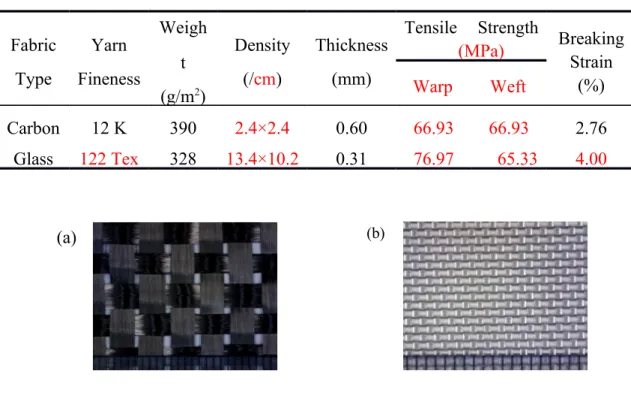
(manufactured by Huvis Corporation, South Korea) had the fineness of 0.44 Tex and length of 51 mm. Two types of woven fabrics, carbon fabric and glass fabric (as shown in Figure 1), were both supplied by Jinsor-Tech Industrial Corp., and their physical and mechanical properties are listed in Table 1.
(b) (a)
Table 1. Physical and mechanical properties of carbon woven fabric and glass woven fabric. Fabric Type Yarn Fineness Weigh t (g/m2) Density (/cm) Thickness (mm) Tensile Strength (MPa) Breaking Strain (%) Warp Weft Carbon 12 K 390 2.4×2.4 0.60 66.93 66.93 2.76 Glass 122 Tex 328 13.4×10.2 0.31 76.97 65.33 4.00
Figure 1. Surface observation of carbon woven fabric (a) and glass woven fabric (b).
Experimental Procedure
Fabric-reinforced composites were produced by three steps based on needle-punching and thermo-bonding techniques. Firstly, 20 wt% of recycled Kevlar fibers, 30 wt% of low-Tm polyester fibers and 50 wt% of high-strength
Nylon 6 staple fibers, optimized in our previous study [20], were made into nonwoven, via processes including opening, blending, carding, lapping and
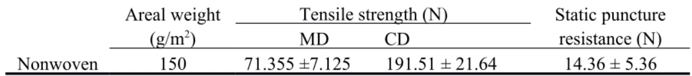
pre-needling (100 needles/cm2). The mechanical property of nonwoven is
displayed in Table 2. Afterwards, single layer of carbon or glass woven fabric was interlayered between double layers of nonwovens by needle-punching, respectively forming carbon-fabric reinforced composite (CRC) and glass-fabric reinforced composite (GRC), during which needle-punched densities were changed from 100, 150, 200 to 250 needles/cm2. In the manufacturing, all
needle-punching process was conducted using #36 Groz-Beckert Triangle
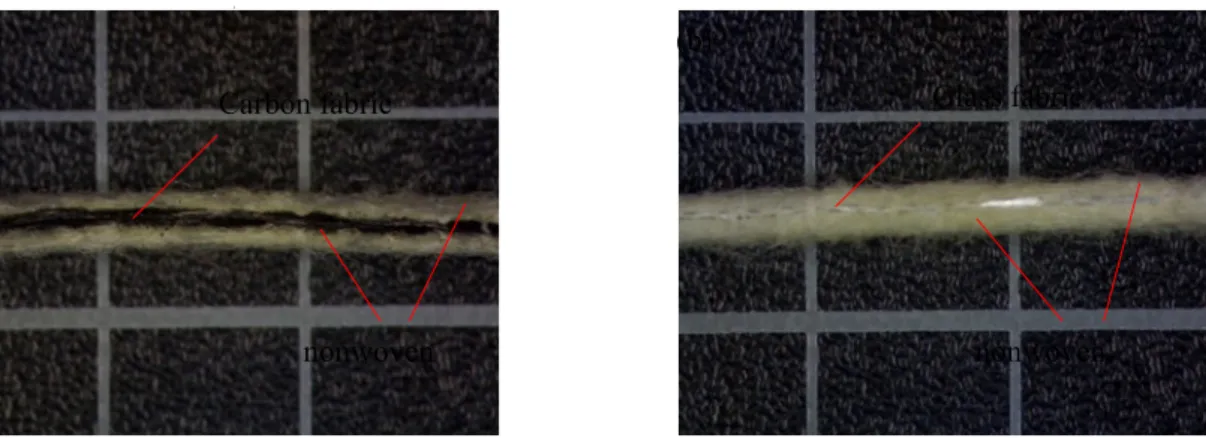
Needle. Ultimately, two different composites were hot-pressed between 1.5-mm-gap Twin-Roller Calender at 160 ℃ in velocity of 0.5 m/min, intended to increase thermo-bonding spots in composites. Also, the CRC and GRC before hot-pressing were retained to discuss hot-pressing effect on the composites. The CRC and GRC before or after hot-pressing are respectively named as non-hot-press CRC, non-non-hot-press GRC, non-hot-press CRC, and non-hot-press GRC. The cross sections of CRC and GRC were respectively shown in Figure 2 (a) and (b). Therein, the microscope observations of composites structure were elaborately examined in our previous studies [21, 22].
Table 2. Tensile and puncture properties of Kevlar/Nylon 6/Low-Tm PET
nonwoven. Areal weight
(g/m2)
Tensile strength (N) Static puncture
resistance (N) MD CD
(a) (b)
nonwoven
Carbon fabric Glass fabric
nonwoven
Figure 2. Cross-section observations of CRC (a) and GRC (b).
Measurements Tensile Property
Single-layer CRC and GRC after being thermo-bonded or un-thermo-bonded were tested according to ASTM D5035-11 standard. The apparatus used for tensile testing is Instron 5566 Universal Tester (Instron, America) with 1 kN load cell. The samples were sized as 180 × 25 mm2, clamped between
76-mm-distance upper and lower fixtures, and then stretched at speed of 300 mm/min. During testing, load-displacement curves were displayed. The maximum tensile strength and elongation was acquired ultimately. Twelve samples, six along the machine direction (MD) and six along the cross machine direction (CD), were duplicated for the mean value.
Air permeability Property
The air permeability was tested using Textest FX3300 (supplied by TEXTEST INSTRUMENT, Germany) based on ASTM D737-04. The air
amount needs to be firstly adjusted at testing pressure of 125 MPa in order to receive more accurate air permeability value which is expressed as air amount per cm3 through per cm2 samples, namely cm3/ cm2/ s. Fourteen regions, sized
as 25 × 25 cm2, were tested respectively for each sample.
Puncture Resistance Properties
For simulating various puncture events, static and dynamic puncture resistances of hot-pressed and un-hot-pressed GRC and CRC were both evaluated in this study. Static puncture resistance was measured by Instron 5566 Universal Tester (Instron, America) at 508 mm/min, according to ASTM F1342-05. 100 × 100 mm2 samples were placed between 180-mm-diameter
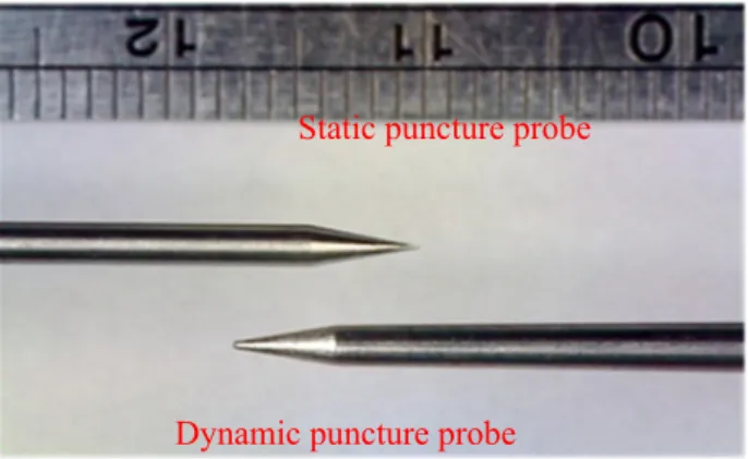
circular plates with 10-mm-diameter opening in the center. Probe with shaft radius of 0.25 mm, conical angle of 26° and conical diameter of 4.06 mm [23] was used as testing head whose specification is given in Figure 3(a). Ten specimens were measured for average values in each group.
Dynamic puncture resistance test of GRC and CRC was conducted on Drop-Tower machine (HungTa, Taiwan) attached with PCD300A data acquisition system, based on NIJ Standard 0115.00. In order to resist against 24 J strike energy at Protection Level 1, the spike (shaft diameter of 1.905 mm and conical angle of 24°) [24] with 2.8 kg load was freely dropped from height of 284 mm, whose dimension was shown in Figure 3(b). Samples sized as 100 mm × 100 mm were clamped between 15 cm ×15 cm square plates with
40-Static puncture probe
Dynamic puncture probe
mm-diameter center hole. Ten specimens were measured repeatedly for the average and standard deviations.
Figure 3. Probes using for static puncture and dynamic puncture tests.
EMI Shielding Effectiveness (SE)
The EMI shielding measurement was conducted according to ASTM D4935. The testing system consisted of EM-2107 sample holder, Advantest R-3132 spectrum analyzer and HP 8752C personal computer, was displayed in Figure 4(a). Therein, the sample holder has 133 mm outer diameter and 33 mm inner diameter, which is given in Figure 4 (b). During testing, electromagnetic radiation was in the form of far-field plane waves. Ultimately, EMI SE vs. frequency profile was displayed on the screen of computer at scanning frequency ranging from 300 K to 3 G Hz.
Sample Holder Sample
33 mm 133 mm
Figure 4. Testing system and sample holder used for EMI shielding [19].
Results and Discussion
Needle-Punching and Thermo-Bonding Effects on Tensile Property
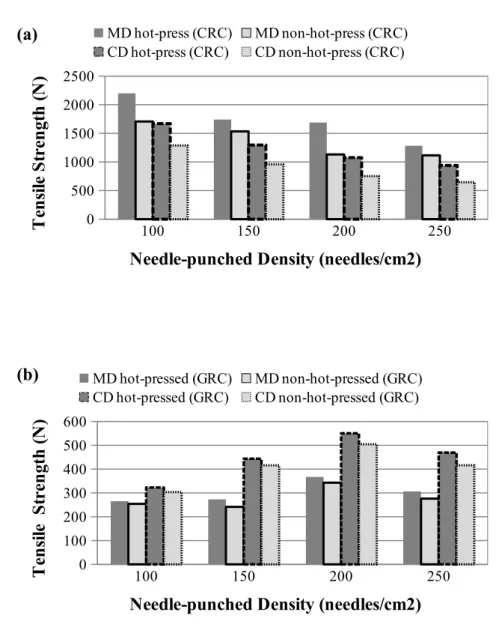
Figure 5 shows the effects of needle-punched density and thermo bonding on tensile strengths of CRC and GRC. As seen in Figure 5(a), the tensile strength of CRC decreases steadily with increase of needle-punched density both in MD and CD. That is, CRC has the maximum tensile strength when being needle-punched at100 needle/cm2. When needle-punched density is higher than 200
needles/cm2, the minimum tensile strength of CRC is lower than that of carbon
(a)
fabric. This reflects that over-bonding damages the carbon fiber, thus resulting in decreased tensile strength. It is found from Figure 5(b) that tensile strength of GRC firstly increases to the maximum when needle-punched density improves to 200 needles/cm2, and then decreases when needle-punched density
is over 200 needles/cm2. The difference of tensile property between CRC and
GRC as related to needle-punched density from 100 to 250 needles/cm2 is due
to the fact that carbon fabric has smaller breaking strain than glass fabric, as presented in Table 2.
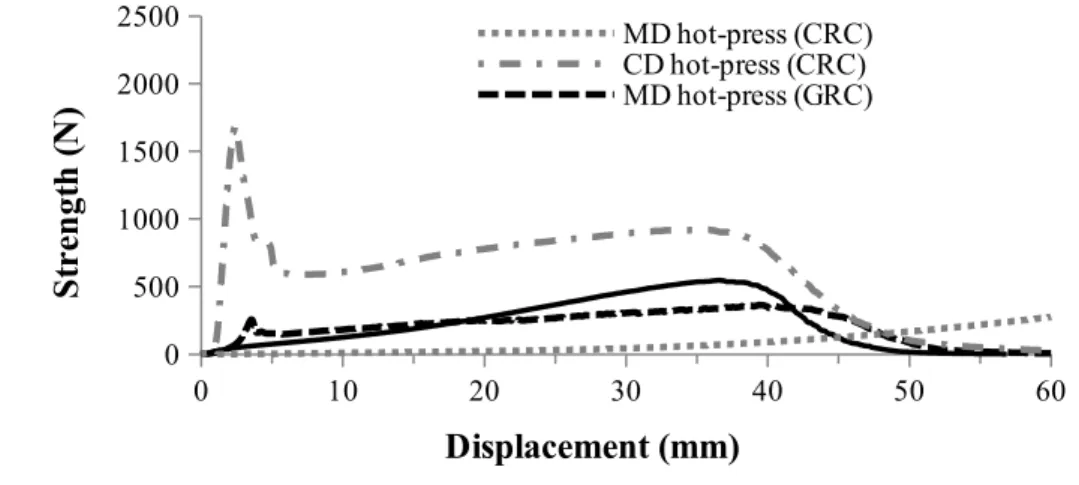
Comparing with Figure 5(a) and (b), tensile strength of CRC and GRC regardless of CD and MD is increased after thermo bonding effect. This is because thermo bonding spots are produced, which improves strength transfer when being subjected to tensile loads. Interestingly, CRC in MD has higher tensile strength than that in CD whatever being un-hot-pressed or hot-pressed; conversely, GRC in CD shows higher tensile strength than that in MD. As displayed in Figure 6, CRC reaches the maximum tensile strength at small elongation both in MD and CD when carbon fabric endures the majority of tensile loading. For GRC, maximum tensile strength in MD happens sooner than that in CD. This demonstrates that GRC has strong bonding between glass fabric and nonwovens in particular cross-direction, which is because more staple fibers were punctured into glass fabrics in this direction. Combined with above tensile behaviors of CRC and GRC, we concluded that Carbon yarn in CD becomes widened under piercing force from needles, leading to the number
of carbon yarn decreased at constant tensile width and thus producing lessening tensile strength in CD. 100 150 200 250 0 500 1000 1500 2000 2500 MD hot-press (CRC) MD non-hot-press (CRC) CD hot-press (CRC) CD non-hot-press (CRC)
Needle-punched Density (needles/cm2)
T en si le S tr en gt h ( N ) 100 150 200 250 0 100 200 300 400 500 600 MD hot-pressed (GRC) MD non-hot-pressed (GRC) CD hot-pressed (GRC) CD non-hot-pressed (GRC)
Needle-punched Density (needles/cm2)
T en si le S tr en gt h ( N )
Figure 5. Tensile strengths of CRC (a) and GRC (b) being non-hot-pressed or hot-pressed after being needle-punched at various densities.
(a)
0 10 20 30 40 50 60 0 500 1000 1500 2000 2500 MD hot-press (CRC) CD hot-press (CRC) MD hot-press (GRC) Displacement (mm) S tr en gt h ( N )
Figure 6. Tensile strength-displacement curves for hot-press CRC and GRC, respectively needle-punched at 100 needles/cm2, and 200 needles/cm2.
Needle-Punching and Thermo-bonding Effects on Air Permeability
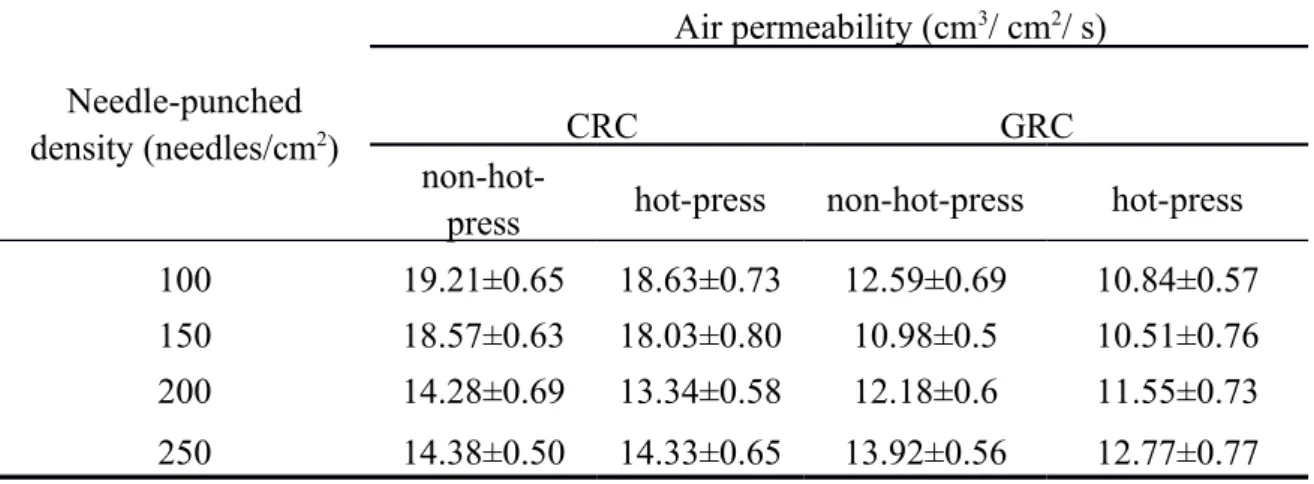
The effects of needle-punched density and thermo-bonding on air permeability are listed in Table 3. It can be found that both the CRC and GRC exhibit a decreasing and then increasing air permeability with increase in needle-punched density whether being hot-pressed or not. As needle-punched density increases, the whole structure of composites becomes more and more compact, because more staple fibers among nonwovens are needle-punched into inter-space of fabrics. Therefore, the air passage becomes more torturous and thus the air permeability tends to be down [25]. However, when needle-punched density exceeds a too high value, the whole structure of composites would be damaged, thus air permeability would be conversely reduced. To sum up, air permeability property would indirectly demonstrate the fiber volume and integrity of composites.
Comparing in Table 3, CRC produces the lowest air permeability at 200 needles/cm2, but GRC emerges at 150 needles/cm2. This is due to the fact that
carbon fabric has bigger yarn density than glass fabric, that is, larger interval volume holds more staple fibers of nonwovens. Furthermore, dense punching effect would bring more fibers in-between fabrics, thus needle-punched density when CRC produces air permeability is higher than that GRC appears.
Thermo-bonding effect on air permeability is also seen from Table 3. Apparently, the air permeability is decreased for both of hot-press CRC and GRC. This is originated from two reasons. Firstly, thermo-bonding points are formed after hot-pressing effect, which would block the channel of air flow among the entirety composites. In addition, superficial pores become lessened after hot-pressing, thus less air have ability to flow into composites.
Table 3. Air permeability results of non-hot-press and hot-press CRC or GRC.
Needle-punched
density (needles/cm2)
Air permeability (cm3/ cm2/ s)
CRC GRC
non-hot-press hot-press non-hot-press hot-press
100 19.21±0.65 18.63±0.73 12.59±0.69 10.84±0.57
150 18.57±0.63 18.03±0.80 10.98±0.5 10.51±0.76
200 14.28±0.69 13.34±0.58 12.18±0.6 11.55±0.73
250 14.38±0.50 14.33±0.65 13.92±0.56 12.77±0.77
Properties
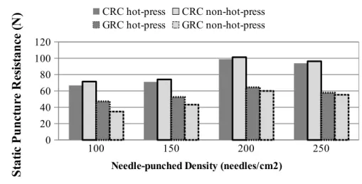
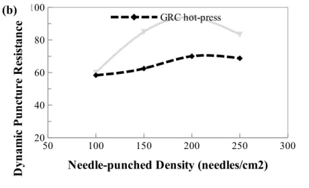
Figures 7 and 8 respectively show static and dynamic puncture resistances of non-hot-press and hot-press of CRC and GRC at various needle-punched densities. It is found that regardless of being thermal-bonded, CRC and GRC needle-punched at 200 needles/cm2 occur maximum static and dynamic
puncture resistances. Meanwhile, with increase of needle-punched density, static and dynamic puncture resistances both show first increase and then decrease trend. This also depends on the effect of the needle-punched density on composites structure. As needle-punched density increases, composites structure becomes more compact due to more staple fibers that were penetrated into the reinforced fabrics. Consequently, contact pressure and friction actions of composites to probe become larger, and static puncture resistance is improved accordingly [26]. However, when composites were needle-punched too dense at per area, the probe easily penetrates through composites that consisted of fractured fibers, and thus resistance of composites to puncture is decreased.
As shown in Figure 7, the non-hot-press CRC and GRC have the maximum static puncture resistance of 101.31 N, and 59.94 N respectively, which is increased by 213%, 14.3%, as compared to non-needle-punched CRC and GRC. This reflects that needle-punched effect significantly improves static puncture resistance. For dynamic puncture property displayed in Figure 8, non-hot-press CRC and GRC have the maximum dynamic puncture resistance of
104.95 N, 93.71 N, as compared to un-needle-punched composites composed of double-layer nonwovens and one-layer Carbon or Glass fabric insertion, less than 24.99 N. This also explains needle-punched effect plays a significant role to dynamic puncture resistance.
It is also observed from Figures 7 and 8 that thermo-bonding have small influence on static puncture resistance, but significantly lowers the dynamic puncture resistance of GRC. Interestingly, non-hot-press CRC has lower dynamic puncture resistance than hot-press CRC when at 100, and 150 needles/cm2, but shows higher dynamic puncture resistance when at 200, and
250 needles/cm2. This implies that needle-punching and thermo-bonding both
have obvious impact on dynamic puncture resistance property. Moreover, CRC shows dramatically higher static and dynamic puncture resistances than GRC when being needle-punched at 200 needles/cm2. Although carbon fabric was
easily damaged after needle-punching, its yarn has 7~ 8 m diameter, which is
much coarser than glass yarn, as revealed in Figure 1. In addition, carbon fabric has smaller cover factor than glass fabric, thus more staple fibers were penetrated from nonwovens to inter-yarn of fabric. As a result, probe has more opportunities to contact with carbon yarn, and simultaneously overcomes bigger pushing forces when probe point entered into CRC. According to above illustrations, both of static and dynamic puncture resistances of optimal CRC is higher than those of GRC.
100 150 200 250 0 20 40 60 80 100 120 CRC hot-press CRC non-hot-press GRC hot-press GRC non-hot-press
Needle-punched Density (needles/cm2)
S ta ti c P u n ct u re R es is ta n ce ( N )
Figure 7. Static puncture resistance property of non-hot-press and hot-press CRC or GRC, after needle-punched at various densities.
50 100 150 200 250 300 20 40 60 80 100 120 CRC hot-press
Needle-punched Density (needles/cm2)
D yn am ic P u n ct u re R es is ta n ce ( N ) (a)
50 100 150 200 250 300 20 40 60 80 100 GRC hot-press
Needle-punched Density (needles/cm2)
D yn am ic P u n ct u re R es is ta n ce ( N )
Figure 8. Dynamic puncture resistance property of CRC (a) and GRC (b) being non-hot-pressed or hot-pressed.
Needle-Punching and Thermo-bonding Effects on EMI SE
As shown in Figure 9, it is obvious that CRC has the EMI shielding
property of 40~ 60 dB at above 1 GHz, which corresponds to greater than
99.99 % attenuation of EMI radiation [29]; but GRC has not ability to shield EMI regardless of non-hot-press or hot-press. Therefore, we will only discuss EMI SE of CRC in the following.
EMI SE behaviors of CRC as related to needle-punching and thermo-bonding effects on EMI SE are respectively shown in Figure 10. As shown in Figure 10 (a), EMI SE improves by 6 dB around 0.65 GHz frequency, and decreases by 13 dB at 0.82 GHz frequency, when needle-punched density increases from 100 needles/cm2 to 150 needles/cm2. Afterwards, CRC displays
identical EMI SE at the whole testing frequency. In Figure 10 (b), EMI SE of
hot-press CRC is found to be almost same at the whole testing frequency, indicating that needle-punching effect have no influence on EMI SE after thermo-bonding.
As referred in [8, 27, 28], EMI SE is the sum of reflection loss R ,
absorption loss A and multi-reflection loss M , as expressed in Eq. (1):
SE=R+ A+ M (1)
Therefore, reflection loss and multi-reflection loss are the main mechanism to shield EMI at low-frequency. As increase in testing frequency, reflection losses are decreased, and meanwhile absorption loss becomes the main shielding mechanism at medium-high frequencies.
3.00E +05 3.75E +08 7.50E +08 1.13E +09 1.50E +09 1.88E +09 2.25E +09 2.63E +09 3.00E +09 -80 -60 -40 -200 Frequency (Hz) CRC hot-press CRC non-hot-press GRC hot-press GRC non-hot-press E M I S E ( d B )
Figure 9. EMI SE of non-hot-press and hot-press of CRC or GRC at needle-punched density of 200 needles/cm2.
3.00E +05 3.75E +08 7.50E +08 1.13E +09 1.50E +09 1.88E +09 2.25E +09 2.63E +09 3.00E +09 -80 -70 -60 -50 -40 -30 -20 -100 Frequency (Hz) 100 needles/cm2 150 needles/cm2 E M I S E ( d B ) 3.00E +05 3.75E +08 7.50E +08 1.13E +09 1.50E +09 1.88E +09 2.25E +09 2.63E +09 3.00E +09 -80 -70 -60 -50 -40 -30 -20 -100 Frequency (Hz) 100 needles/cm2 150 needles/cm2 E M I S E ( d B )
Figure 10. EMI SE of non-hot-press (a) and hot-press (b) CRC at different needle-punched densities.
Conclusion
In this study, carbon-fabric reinforced composite (CRC) and glass-fabric reinforced composite (GRC) were prepared by needle-punching and thermo-bonding effects, after that, their respective tensile strength, air permeability, static and dynamic puncture resistances, as well as EMI shielding effectiveness were discussed comparatively.
When needle-punched density increases from 100 to 250 needles/cm2, CRC
shows a decrease to tensile strength, but GRC presents an increasing and then decreasing tensile strength. In addition, needle-punched density also has a double-faced effect on static and dynamic puncture resistances, that is, puncture resistances firstly improve and then reduce as needle-punched density increases. Thermo-bonding is positive to improvement of tensile strength, but negative to dynamic puncture resistances. Meanwhile, resistance, thermo-bonding almost plays no role to static puncture resistance, which is similar to EMI shielding.
Comparatively, CRC has higher static and dynamic puncture resistance than GRC when being needle-punched at 100 needles/cm2. In addition, when
frequency is over 1GHz, CRC shows superior EMI SE of 40~60dB, indicating
that 99.99% shielding for EMI. Therefore, resultant CRC made by in this study would be successfully used professional protective armor, and GRC would be used as interlayer for puncture-resisting armor. In the following study, we will focus on effect of number of layers on EMI shielding effectiveness and puncture resistance properties of CRC.
Acknowledgements
We are grateful to Taiwan Science Council for providing financial support (NSC101-2621-M-166-001).
References
1. H. Kim and I. Nam, J. Appl. Polym. Sci, 123(5),2733 (2012).
2. M. J. Decker, C. J. Halbach, C. H. Nam, N. J. Wagner and E. D. Wetzel, Compos. Sci. and Technol., 67, 565 (2007).
3. D. P. Kalman, R. L. Merrill, N. J. Wagner, E. D. Wetzel, ACS Appl. Mater. Inter., 1(11), 2602 (2009).
4. T. J. Kang, K. H. Hong and M. R. Yoo, Fiber. Polym., 11(5), 719 (2010).
5. T. A. Hassan, V. K. Rangari and S. Jeelani, Mat. Sci. Eng. A—Struct., 527, 2892 (2010).
6. E. M. Croitoro and I. E. Boros, T. Can. Soc. Mech. Eng., 31(2), 157 (2007).
7. J. B. Mayo Jr, E. D. Wetzel, M. V. Hosur and S. Jeelani, Int. J. Impact Eng., 36, 1095 (2009).
8. D. D. L. Chung, Carbon, 39, 279 (2001).
9. L. Li, D. D. L. Chung, Composites, 25(3), 215 (1994).
10.X. Shui and D. D. L. Chung, J. Electron. Mater., 26(8), 928 (1997).
11.D. D. L. Chung, J. Mater. Sci., 39(8), 2645 (2004).
12.X. Fu, D. D. L. Chung, Carbon, 36(4), 459 (1998).
13.J. M. Chiou, Q. Zheng, D. D. L. Chung, Composites, 20(4), 379 (1989).
14.H. Aniolczyk, J. Koprowska, P. Mamrot and J. Lichawska, Fibers Text. East. Eur., 12(4), 47 (2004).
1039 (2000).
16.J. H. Lin and C.W. Lou, Text. Res. J., 73(4), 322 (2003).
17.H. C. Chen, K. C. Lee and J. H. Lin, Compos. Part A—Appl. S., 35(11), 1249 (2004).
18.H. C. Chen, K. C. Lee, J. H. Lin and M. Koch, J. Mater. Process. Tech., 184 (1-3), 124 (2007).
19.C. W. Lou, C. M. Lin, W. H. Hsing, A. P. Chen and J. H. Lin, Text. Res. J., 81(13), 1331 (2011).
20.T. T. Li, R. Wang, C. W. Lou and J. H. Lin, J. Ind. Text., Publish on line (2012).
21.T. T. Li, R. Wang, C. W. Lou and J. H. Lin, Text. Res. J., 82, 1597 (2012).
22.T. T. Li, R. Wang, C. W. Lou, C.H. Hung and J. H. Lin, Fiber. Polym., 14(2), 258 (2013).
23.ASTM F1342. Standard Test Method for Protective Clothing Material Resistance to Puncture (2005).
24.NIJ Standard-0115.00. Stab Resistance of Personal Body Armor (2000).
25.M. Mohammadi, P. Banks-Lee and P. Ghadimi, J. Ind. Text., 32(1), 45 (2002).
26.Termonia Y, Int. J. Impact Eng., 32, 1512 (2006).
27.A. A. Al-Ghamdi, F. El-Tantawy, N. A. Aal, E. H. El-Mossalamy and W. E. Mahmoud, Polym. Degrad. Stabil., 94, 980 (2009).
28.M. H. Al-Saleh and U. Sundararaj, Carbon, 47, 1738 (2009).
![Figure 4. Testing system and sample holder used for EMI shielding [19].](https://thumb-ap.123doks.com/thumbv2/9libinfo/8949320.273596/11.892.149.670.120.627/figure-testing-system-sample-holder-used-emi-shielding.webp)